EP1515422A2 - Appareil de contrôle de sortie pour source d'énergie électrique - Google Patents
Appareil de contrôle de sortie pour source d'énergie électrique Download PDFInfo
- Publication number
- EP1515422A2 EP1515422A2 EP04255328A EP04255328A EP1515422A2 EP 1515422 A2 EP1515422 A2 EP 1515422A2 EP 04255328 A EP04255328 A EP 04255328A EP 04255328 A EP04255328 A EP 04255328A EP 1515422 A2 EP1515422 A2 EP 1515422A2
- Authority
- EP
- European Patent Office
- Prior art keywords
- output
- voltage
- input
- control device
- power source
- Prior art date
- Legal status (The legal status is an assumption and is not a legal conclusion. Google has not performed a legal analysis and makes no representation as to the accuracy of the status listed.)
- Withdrawn
Links
Images


Classifications
-
- H—ELECTRICITY
- H01—ELECTRIC ELEMENTS
- H01M—PROCESSES OR MEANS, e.g. BATTERIES, FOR THE DIRECT CONVERSION OF CHEMICAL ENERGY INTO ELECTRICAL ENERGY
- H01M8/00—Fuel cells; Manufacture thereof
- H01M8/04—Auxiliary arrangements, e.g. for control of pressure or for circulation of fluids
-
- H—ELECTRICITY
- H02—GENERATION; CONVERSION OR DISTRIBUTION OF ELECTRIC POWER
- H02M—APPARATUS FOR CONVERSION BETWEEN AC AND AC, BETWEEN AC AND DC, OR BETWEEN DC AND DC, AND FOR USE WITH MAINS OR SIMILAR POWER SUPPLY SYSTEMS; CONVERSION OF DC OR AC INPUT POWER INTO SURGE OUTPUT POWER; CONTROL OR REGULATION THEREOF
- H02M3/00—Conversion of DC power input into DC power output
- H02M3/02—Conversion of DC power input into DC power output without intermediate conversion into AC
- H02M3/04—Conversion of DC power input into DC power output without intermediate conversion into AC by static converters
- H02M3/10—Conversion of DC power input into DC power output without intermediate conversion into AC by static converters using discharge tubes with control electrode or semiconductor devices with control electrode
- H02M3/145—Conversion of DC power input into DC power output without intermediate conversion into AC by static converters using discharge tubes with control electrode or semiconductor devices with control electrode using devices of a triode or transistor type requiring continuous application of a control signal
- H02M3/155—Conversion of DC power input into DC power output without intermediate conversion into AC by static converters using discharge tubes with control electrode or semiconductor devices with control electrode using devices of a triode or transistor type requiring continuous application of a control signal using semiconductor devices only
- H02M3/156—Conversion of DC power input into DC power output without intermediate conversion into AC by static converters using discharge tubes with control electrode or semiconductor devices with control electrode using devices of a triode or transistor type requiring continuous application of a control signal using semiconductor devices only with automatic control of output voltage or current, e.g. switching regulators
-
- Y—GENERAL TAGGING OF NEW TECHNOLOGICAL DEVELOPMENTS; GENERAL TAGGING OF CROSS-SECTIONAL TECHNOLOGIES SPANNING OVER SEVERAL SECTIONS OF THE IPC; TECHNICAL SUBJECTS COVERED BY FORMER USPC CROSS-REFERENCE ART COLLECTIONS [XRACs] AND DIGESTS
- Y02—TECHNOLOGIES OR APPLICATIONS FOR MITIGATION OR ADAPTATION AGAINST CLIMATE CHANGE
- Y02E—REDUCTION OF GREENHOUSE GAS [GHG] EMISSIONS, RELATED TO ENERGY GENERATION, TRANSMISSION OR DISTRIBUTION
- Y02E60/00—Enabling technologies; Technologies with a potential or indirect contribution to GHG emissions mitigation
- Y02E60/30—Hydrogen technology
- Y02E60/50—Fuel cells
Definitions
- the present invention relates to an output control device for an electric power source, having a converter circuit for converting an input voltage from the electric power source to an output voltage and, in particular, to an output control device for protecting an electric power source by preventing malfunction due to a sharp drop in the input voltage from the electric power source having a relatively large internal impedance.
- Output control device control an input from an electric power source such as a fuel cell with a switching power supply circuit thereof, thereby controlling an output to a load.
- Known output control device typically include an output short-circuit protective circuit, an output excessive current protective circuit, or an input excessive voltage protective circuit, etc.
- These protective circuits protect the switching power supply circuit, or a circuit, electrical components, and devices connected thereto as a load, but does not protect the electric power source.
- the output short protective circuit and the output excessive current protective circuit limit input power from the electric power source, namely, these protective cirsuits limit the input power to the switching supply circuit-.
- the level of protection provided by the protective circuit for protecting the electric power source is not satisfactory because the precision of the circuit for limiting power is poor, and because the protective circuit does not monitor directly an input voltage Vin and an input current Iin.
- Japanese Patent Application Publications Nos. 10-284102 and 11-144749 disclose techniques for protecting an electric power source such as a fuel cell.
- a function generator is arranged to input an output command to an inverter to set an upper limit value of a direct current responsive to the output command.
- a direct current detector is arranged to detect a direct current supplied from a fuel cell to the inverter. The inverter is controlled so that the direct current value detected by the director current detector does not exceed the upper limit value of the direct current from the function generator.
- a second voltage value higher than a first voltage value set for stopping an abnormal operation of a fuel cell, is set to monitor the voltage of the fuel cell. If the voltage of the fuel cell reaches the second voltage value, an input current to a power adjuster is gradually lowered.
- the input current to the inverter or the power adjuster is lowered, the input voltage thereto rises. As a result, the output current falls resulting in the output power being insufficient to drive a load.
- an output current or an output power increases in an electric power source, such as a fuel cell having a relatively high internal impedance
- the output voltage of the electric power source falls due to a voltage drop across the internal impedance
- An output control device is typically used to control the output of the electric power source.
- the electric power source switches the output voltage of a electric power source such as a fuel cell before providing the output to a load.
- an output current of the electric power source namely, an input current Iin to the output control device can rise above a predetermined value. If the input current Iin rises above the predetermined value, an output voltage of the electric power source, namely, an input voltage Vin to the output control device is lowered, leading to a positive feedback operation in which the input current Iin to the output control device further increases while the input voltage Vin further decreases.
- an input voltage Vin continuously decreases, and the output control device is unable to maintain the output voltage Vout to a desired value.
- an object of the present invention is to provide an output control device for an electric power source for preventing the electric power source from malfunctioning due to a sharp drop in an input current from the electric power source having a relatively high internal impedance to protect the electric power source, and maintaining a connected load at a stable operation.
- an output control device for an electric power source includes a converter circuit for converting an input voltage from the electric power source to an output voltage, and an input detector circuit for detecting an input from the electric power source, wherein the converter circuit has a lower limit value sustaining mode under which the lower limit value of the input voltage is maintained to a predetermined value in response to the output voltage of the input detector circuit.
- the input detector circuit detects at least one of an input voltage, an input current, and an input power to the output control device from the electric power source.
- the lower limit value of the input voltage is maintained to the predetermined value by varying the output voltage in the lower limit value sustaining mode.
- an output current to a load is heightened by maintaining the lower limit value of the input voltage to the predetermined value in the lower limit value sustaining mode.
- the converter circuit further has a constant voltage control mode for controlling the output voltage to a constant value by detecting the output voltage, and the converter circuit switches between the constant voltage control mode and the lower limit value sustaining mode in response to the detected output of the input detector circuit.
- an output control device for an electric power source includes a converter circuit for converting an input voltage from the electric power source to an output voltage, and an input detector circuit for detecting a variation in an input from the electric power source, wherein the converter circuit has a current increasing mode in which an output current is increased while the variation in the input detected by the input detector circuit is maintained to within a constant range by varying the output voltage.
- the input detector circuit detects at least one of a variation in an input voltage, a variation in an input current, and a variation in an input power from the electric power source.
- the converter circuit has a constant voltage control mode in which the converter circuit detects the output voltage to control the output voltage to a constant value, and the converter circuit switches between the constant voltage control mode and the current increasing mode in response to the detected output from the input detector circuit.
- an output control device for an electric power source includes a converter circuit for converting an input voltage from the electric power source to an output voltage, a lower limit detector circuit for outputting a predetermined signal when the input voltage from the electric power source falls below a predetermined threshold value, and an output voltage detector circuit for detecting the output voltage, wherein the converter circuit controls a conversion condition under which the input voltage is converted to the output voltage based on the output voltage detected by the output voltage detector circuit and the output from the lower limit detector circuit.
- an output control device for an electric power source includes a converter circuit for converting an input voltage from the electric power source to an output voltage, an upper limit detector circuit for outputting a predetermined signal when the input voltage from the electric power source rises above a predetermined threshold value, and an output voltage detector circuit for detecting the output voltage, wherein the converter circuit controls a conversion condition under which the input voltage is converted to the output voltage based on the output voltage detected by the output voltage detector circuit and the output from the upper limit detector circuit.
- an output control device for an electric power source includes a converter circuit for converting an input voltage from the electric power source to an output voltage, a variation detector circuit for detecting a variation in an input from the electric power source, wherein the converter circuit controls a conversion condition under which the input voltage is converted to the output voltage based on the variation amount detected by the variation amount detector.
- the variation amount detector circuit detects at least one of a variation in an input voltage, a variation in an input current, and a variation in an input power from the electric power source.
- the input detector circuit detects the input voltage, the input current, and the input power from the electric power source
- the converter circuit for converting the input voltage from the electric power source to the output voltage has the lower limit value sustaining mode in which the lower limit value of the input voltage is maintained to the predetermined value in response to the detected output of the input detector circuit.
- the input detector circuit detects the variations in the input voltage, the input current, and the input power from the electric power source, and the converter circuit for converting the input voltage from the electric power source to the output voltage has the current increasing mode in which the output current is increased while the variation in the input detected by the input detector circuit is maintained to within the constant range by varying the output voltage.
- This arrangement prevents the output voltage of the electric power source from dropping below a specified value of the electric power source, thereby avoiding damaging the electric power source. Since sufficient power to drive a load is picked up from the output of the electric power source, operational stability of the load is assured.
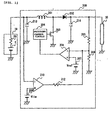
- Fig. 1 is a circuit diagram of an output control device 200 of an electric power source in accordance with a first preferred embodiment of the present invention.
- the output control device 200 supplies power from a fuel cell 10 as an electric power source to a load 30.
- the fuel cell 10 includes a power source E having a large internal impedance R0.
- the output control device 200 includes a coil 201 receiving the output of the fuel cell 10, a field-effect transistor 203 for switching the output of the coil 201, a diode 202, a pulse-width modulation (PWM) circuit 204 for switch controlling the field-effect transistor 203, resistors 205 and 206 for detecting an output voltage Vout of the output control device 200, a reference voltage generator 207 for generating a reference voltage Vref controlling the PWM circuit 204, a differential amplifier 208 for generating a control signal for controlling the PWM circuit 204, a lower limit value setter 209 for setting a lower limit value Vlim of an input voltage Vin of the output control device 200, a comparator 210 having a negative terminal receiving the input voltage Vin of the output control device 200 and a positive terminal receiving the lower limit value Vlim set by the lower limit value setter 209 to compare the input voltage Vin with the lower limit value Vlim, and resistors 212 for pulling up the output of the comparator 210.
- PWM pulse-wid
- the output of the comparator 210 remains at a low level (ground level) when the output voltage of the fuel cell 10, namely, the input voltage Vin of the output control device 200 is above the lower limit value Vlim set by the lower limit value setter 209.
- the output voltage Vout of the output control device 200 is voltage divided by a resistor 205 and a parallel circuit of resistors 212 and 206, and the divided voltage V1 is applied to a negative input terminal of the differential amplifier 208.
- the differential amplifier 208 then applies a voltage difference between the voltage V1 and a reference voltage Vref to the PWM circuit 204.
- the PWM circuit 204 turns on and off the field-effect transistor 203, thereby controlling the output voltage Vout of the output control device 200 to a substantially constant voltage with respect to the reference voltage Vref (constant voltage control mode).
- the output voltage Vout of the output control device 200 is voltage divided by the resistor 206 and a parallel circuit of resistors 212 and 205, and the divided voltage V2 (>V1) is input to the negative input terminal of the differential amplifier 208.
- the differential amplifier 208 applies a voltage difference between the voltage V2 and the reference voltage Vref to the PWM circuit 204.
- the PWM circuit 204 turns on and off the field-effect transistor 203, thereby controlling the output voltage Vout of the output control device 200 to a voltage lower than the reference voltage Vref.
- the output voltage of the fuel cell 10 namely, the input voltage Vin of the output control device 200 is maintained to the lower limit value Vlim set by the lower limit value setter 209 (lower limit value sustaining mode).
- an output current Iout output from the output control device 200 rises as the output voltage Vout of the output control device 200 falls (current increasing mode).
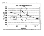
- Fig. 2 is a graph plotting output current versus input voltage/ output voltage characteristics of the output control device 200 of Fig. 1.
- the output voltage Vout of the output control device 200 is controlled to a substantially constant voltage even if the input voltage Vin of the output control device 200 varies (the constant voltage control model).
- the output voltage Vout of the output control device 200 is controlled to a voltage lower than the substantially constant voltage in the constant voltage control mode. In this case, the input voltage Vin of the output control device 200 is maintained to the lower limit value Vlim (the lower limit value sustaining mode).
- the output current Iout of the output control device 200 rises as the output voltage Vout of the output control device 200 falls (current increasing mode).
- the efficiency of the output control device 200 becomes slightly lower in the lower limit value sustaining mode than in the constant voltage control mode, but remains high.
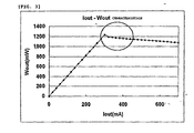
- Fig. 3 is a graph plotting output current versus output power characteristics of the output control device 200 of Fig. 1.
- the output control device 200 picks up large power in an area of shift from the constant voltage control mode to the lower limit value sustaining mode (circled regions in Fig. 2 and Fig. 3).
- the output of the comparator 210 remains at a low level when the input voltage Vin of the output control device 200 is higher than the lower limit value Vlim.
- the output voltage Vout of the output control device 200 is controlled to a substantially constant voltage in the constant voltage control mode even if the input voltage Vin of the output control device 200 varies. If the input voltage Vin of the output control device 200 falls below the lower limit value Vlim set by the lower limit value setter 209, the output of the comparator 210 is transitioned to a high level.
- the output voltage Vout of the output control device 200 is controlled to a low voltage, and the input voltage Vin of the output control device 200 is maintained to the lower limit value Vlim in the lower limit value sustaining mode.
- the output current Iout output from the output control device 200 rises in the current increasing mode as the output voltage Vout of the output control device 200 falls.
- the output voltage of the fuel cell 10 is prevented from falling below the specified value thereof.
- the fuel cell 10 is thus protected from damage. Even if the output voltage Vout of the output control device 200 falls, the output current Iout rises, and sufficient power to drive the load 30 is provided.
- the load 30 thus operates in a stable manner.
- the output voltage of the fuel cell 10 namely, the input voltage Vin of the output control device 200 is monitored to switch between the constant voltage control mode and the lower limit value sustaining mode (the current increasing mode) in response to the input voltage Vin of the output control device 200.
- the output control device 200 may monitor an input current Iin of the output control device 200 instead of an input voltage Vin of the output control device 200.
- an input power Win of the output control device 200 may be monitored.
- Fig. 4 is a circuit diagram of an output control device 300 of the electric power source in accordance with a second preferred embodiment of the present invention.
- the output control device 300 supplies power to a load 30 from a fuel cell 10 as an electric power source.
- the output control device 300 includes a resistor 301 along an output line of the fuel cell 10.
- An amplifier 302 detects a voltage drop across the resistor 301, thereby detecting the output current of the fuel cell 10, namely, the input current Iin of the output control device 300.
- the input current Iin detected by the amplifier 302, is supplied to a positive input terminal of a comparator 310.
- the comparator 310 receives, at the negative input terminal thereof, an upper limit value Ilim of the input current Iin of the output control device 300 set by an upper limit value setter 309.
- the rest of the structure of the output control device 300 remains identical to the output control device 200.
- elements identical to those described with reference to Fig. 1 are designated with the same reference numerals for convenience of explanation.
- the output of the comparator 210 is at a low level (ground level) when the output current of the fuel cell 10, namely, the input current Iin of the output control device 300 is lower than the upper limit value Ilim set by an upeer limit value setter 309.
- the output voltage Vout of the output control device 300 is voltage divided by the resistor 205 and a parallel circuit of resistors 212 and 206, and the divided voltage V1 is input to the negative input terminal of the differential amplifier 208.
- the differential amplifier 208 supplies the PWM circuit 204 with a voltage difference between the voltage V1 and the reference voltage Vref. In response to the voltage difference, the PWM circuit 204 turns on and off the field-effect transistor 203, thereby controlling the output voltage Vout of the output control device 300 to a substantially constant voltage with respect to the reference voltage Vref (constant voltage control mode).
- the output voltage Vout of the output control device 300 is voltage divided by the resistor 206 and the parallel circuit of resistors 212 and 205, and the divided voltage V2 (>V1) is fed to the negative input terminal of the differential amplifier 208.
- the differential amplifier 208 supplies the PWM circuit 204 with a voltage difference between the voltage V2 and the reference voltage Vref. In response to the voltage difference, the PWM circuit 204 turns on and off the field-effect transistor 203, thereby controlling the output voltage Vout of the output control device 300 to be lower than a voltage corresponding to the reference voltage Vref. In this case, the output current of the fuel cell 10, namely, the input current Iin of the output control device 300 is maintained to the upper limit value Ilim set by the upper limit value setter 309.
- the output voltage of the fuel cell 10, namely, the input voltage Vin of the output control device 300 is maintained to the lower limit value Vlim corresponding to the upper limit value Ilim set by the upper limit value setter 309 (lower limit value sustaining mode).
- the output current Iout output from the output control device 300 rises as the output voltage Vout of the output control device 300 falls (current increasing mode).
- the output voltage of the fuel cell 10 is prevented from falling below the specified voltage value thereof, and the fuel cell 10 is thus protected from damage. Even if the output voltage Vout of the output control device 300 falls, the output current Iout rises. The output control device 300 picks up sufficient power to drive the load 30 thereby driving the load 30 in a stable manner.
- Fig. 5 is a circuit diagram of an output control device 400 of the electric power source in accordance with a third preferred embodiment of the present invention.
- the output control device 400 supplies the load 30 with power from the fuel cell 10 as an electric power source.
- the output control device 400 monitors a variation ⁇ V in the output voltage of the fuel cell 10, namely, the input voltage Vin of the output control device 400.
- a capacitor 213 is connected to the input line from the fuel cell 10 with one terminal and the other terminal thereof grounded.
- a capacitor 214 is connected to a diode 202 with one terminal thereof connected to the output line of the diode 202 and with the other terminal thereof grounded.
- the input line from the fuel cell 10 is connected to the output line of the diode 202 through a capacitor 403, and resistors 405 and 404.
- a transistor 406 is configured with the base thereof connected to the node of the resistors 405 and 404, with the emitter thereof connected to the output line of the diode 202, and with the collector thereof connected to the negative input terminal of the differential amplifier 208.
- the rest of the structure of the output control device 400 remains unchanged from the output control device 200 of Fig. 1.
- elements identical to those of the output control device 200 described with reference to Fig. 1 are designated with the same reference numerals for convenience of explanation.
- a variation in the output voltage of the fuel cell 10 namely, a variation ⁇ V in the input voltage Vin of the output control device 400 is detected by a circuit of the capacitor 403, and the resistors 405 and 404.
- the transistor 406 remains off.
- the output voltage Vout of the output control device 400 is controlled to a substantially constant voltage with respect to the reference voltage Vref (constant voltage control mode).
- the transistor 406 When the input voltage Vin of the output control device 400 falls, and the variation ⁇ V exceeds the value set by the capacitor 403, and the resistors 405 and 404, the transistor 406 operates.
- the transistor 406 in the operative state thereof practically lowers the impedance of the resistor 205 that detects the output voltage Vout of the output control device 400, thereby heightening the input at the negative input terminal of the differential amplifier 208.
- the differential amplifier 208 raises the output thereof, thereby causing the PWM circuit 204 to turn on and off the field-effect transistor 203.
- a conversion condition for converting the input voltage Vin to the output voltage Vout is thus controlled so that the output voltage Vout of the output control device 400 is set to be lower than a voltage corresponding to the reference voltage Vref.
- a drop in the output voltage of the fuel cell 10 namely, a drop in the input voltage Vin of the output control device 400 is controlled not to exceed a specified value (lower limit value sustaining mode).
- the output current Iout of the output control device 400 rises as the output voltage Vout of the output control device 400 falls (current increasing mode).
- Fig. 6 is a graph plotting output current versus input voltage/ output voltage characteristics of the output control device 400 of Fig. 5.
- the output voltage Vout of the output control device 400 is controlled to a substantially constant voltage (constant voltage control mode).
- the output voltage Vout of the output control device 400 is controlled to be lower than the constant voltage in the constant voltage control mode. In this case, the drop in the input voltage Vin of the output control device 400 is controlled not to exceed the specified value (lower limit value sustaining mode).
- the output current Iout of the output control device 400 rises as the output voltage Vout of the output control device 400 falls (current increasing mode).
- the efficiency of the output control device 400 becomes slightly lower in the lower limit value sustaining mode than in the constant voltage control mode, but remains high.
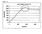
- Fig. 7 is a graph plotting output current versus output power characteristics of the output control device 400 of Fig. 5.
- the output control device 400 picks up large power in an area of shift from the constant voltage control mode to the lower limit value sustaining mode (circled regions in Fig. 6 and in Fig. 7).
- the output voltage of the fuel cell 10 is prevented from falling below the specified value, and the fuel cell 10 is thus protected from damage. Even if the output voltage Vout of the output control device 400 falls, the output current Iout rises, and sufficient power to drive the load 30 is provided. The load 30 thus operates in a stable manner.
- the third preferred embodiment of Fig. 5 avoids a sharp change in the output voltage of the fuel cell 10, further protecting the fuel cell 10 from damage.
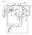
- Fig. 8 is a circuit diagram of an output control device 500 of the electric power source in accordance with a fourth preferred embodiment of the present invention.
- the output control device 500 supplies the load 30 power from the fuel cell 10 as an electric power source.
- a resistor 501 for detecting a current is arranged along the output line of the fuel cell 10.
- An amplifier 502 detects a voltage drop across the resistor 501.
- the output of the amplifier 502 is grounded through a capacitor 503, and resistors 504 and 505.
- a transistor 506 is configured with the emitter thereof connected to the node of the resistors 504 and 505, with the emitter thereof connected to a resistor 405, and with the collector thereof grounded.
- a variation ⁇ I in the output current of the fuel cell 10 namely, in the input current Iin of the output control device 500 is detected.
- the rest of the structure of the output control device 500 remains unchanged from the output control device 400 of Fig. 5.
- elements identical in function to those in the output control device 400 of Fig. 5 are designed with the same reference numerals for convenience of explanation.
- the variation ⁇ I in the output voltage of the fuel cell 10 namely, the variation ⁇ I in the input current Iin of the output control device 500 is detected by the circuit of the capacitor 503 and the resistors 504 and 505.
- the transistor 506 remains off.
- the output voltage Vout of the output control device 500 is controlled to a substantially constant voltage with respect to the reference voltage Vref (constant voltage control mode).
- the transistor 506 operates, thereby raising the input to the negative input terminal of the differential amplifier 208.
- the differential amplifier 208 raises the output thereof, thereby causing the PWM circuit 204 to turn on and off the field-effect transistor 203.
- a conversion condition for converting the input voltage Vin to the output voltage Vout is thus controlled so that the output voltage Vout of the output control device 500 is set to be lower than a voltage corresponding to the reference voltage Vref, so that a drop in the output voltage of the fuel cell 10, namely, a drop in the input voltage Vin of the output control device 500 is controlled not to exceed a specified value (lower limit value sustaining mode).
- the output current Iout of the output control device 500 rises as the output voltage Vout of the output control device 500 falls (current increasing mode).
- the output voltage of the fuel cell 10 is prevented from falling below the specified value, and the fuel cell 10 is thus protected from damage. Even if the output voltage Vout of the output control device 500 falls, the output current Iout rises, and sufficient power to drive the load 30 is thus provided. The load 30 thus operates in a stable manner.
- the fourth preferred embodiment of Fig. 8 avoids a sharp change in the output voltage of the fuel cell 10, further protecting the fuel cell 10 from damage.
- the output control devices for the electric power source uses a fuel cell as power source have been discussed.
- the present invention is applicable to an output control device for an electric power source having a relatively large internal impedance, such as a lithium battery.
- the present invention is applicable to the output control device for the electric power source having the relatively large impedance, the output control device including the converter for converting the input voltage from the electric power source to the output voltage.
- the output control device also includes the input detector circuit for detecting the input voltage, the input current, and the input power from the electric power source, the variation in the input voltage, the variation in the input current, and the variation in the input power from the electric power source.
- the converter circuit for converting the input voltage from the electric power source to the output voltage has the lower limit value sustaining mode in which the lower limit value of the input voltage is maintained to the predetermined value in response to the detected output of the input detector circuit. The output voltage of the electric power source is thus prevented from falling below the specified value, thereby protecting the electric power source from damage. Since sufficient power to drive the load is picked up from the output of the electric power source, operational stability of the load is assured.
Landscapes
- Engineering & Computer Science (AREA)
- Power Engineering (AREA)
- Life Sciences & Earth Sciences (AREA)
- Manufacturing & Machinery (AREA)
- Sustainable Development (AREA)
- Sustainable Energy (AREA)
- Chemical & Material Sciences (AREA)
- Chemical Kinetics & Catalysis (AREA)
- Electrochemistry (AREA)
- General Chemical & Material Sciences (AREA)
- Dc-Dc Converters (AREA)
- Control Of Electrical Variables (AREA)
Applications Claiming Priority (2)
| Application Number | Priority Date | Filing Date | Title |
|---|---|---|---|
| JP2003312791 | 2003-09-04 | ||
| JP2003312791A JP2005086843A (ja) | 2003-09-04 | 2003-09-04 | 電力供給源の出力制御装置 |
Publications (2)
| Publication Number | Publication Date |
|---|---|
| EP1515422A2 true EP1515422A2 (fr) | 2005-03-16 |
| EP1515422A3 EP1515422A3 (fr) | 2005-07-06 |
Family
ID=34131870
Family Applications (1)
| Application Number | Title | Priority Date | Filing Date |
|---|---|---|---|
| EP04255328A Withdrawn EP1515422A3 (fr) | 2003-09-04 | 2004-09-02 | Appareil de contrôle de sortie pour source d'énergie électrique |
Country Status (5)
| Country | Link |
|---|---|
| US (1) | US7279878B2 (fr) |
| EP (1) | EP1515422A3 (fr) |
| JP (1) | JP2005086843A (fr) |
| KR (1) | KR100829549B1 (fr) |
| CN (1) | CN1591954A (fr) |
Cited By (3)
| Publication number | Priority date | Publication date | Assignee | Title |
|---|---|---|---|---|
| EP1988623A2 (fr) | 2007-05-01 | 2008-11-05 | Yamaha Corporation | Convertisseur de courant continu, appareil de haut-parleur et procédé de contrôle de convertisseur |
| CN101436824B (zh) * | 2007-11-12 | 2012-05-30 | 立锜科技股份有限公司 | 提供给切换式调节器的精准平均电流限制电路及方法 |
| EP2112757A3 (fr) * | 2008-04-23 | 2016-11-30 | Honeywell International Inc. | Systèmes et procédés pour la production d'une tension de sortie sensiblement constante dans un système suralimenteur d'alimentation électrique |
Families Citing this family (35)
| Publication number | Priority date | Publication date | Assignee | Title |
|---|---|---|---|---|
| WO2005031956A1 (fr) * | 2003-09-25 | 2005-04-07 | Koninklijke Philips Electronics N.V. | Convertisseur de puissance en mode commute |
| JP4352886B2 (ja) * | 2003-12-11 | 2009-10-28 | 株式会社デンソー | 昇圧回路 |
| US7538534B2 (en) * | 2004-11-29 | 2009-05-26 | Supentex, Inc. | Method and apparatus for controlling output current of a cascaded DC/DC converter |
| DE102005018596A1 (de) * | 2005-04-21 | 2007-01-25 | Siemens Ag Österreich | Verfahren zum Betreiben eines Wechselrichters mit vorgeschaltetem Hochsetzer |
| FR2889001A1 (fr) * | 2005-07-22 | 2007-01-26 | Atmel Nantes Sa Sa | Dispositif de conversion d'une tension d'alimentation continue en une tension de sortie continue et circuit electronique correspondant |
| DE102005050337A1 (de) * | 2005-10-20 | 2007-04-26 | Siemens Ag | Gleichstromsteller und Verfahren zum Betreiben eines Gleichstromstellers |
| US8441210B2 (en) | 2006-01-20 | 2013-05-14 | Point Somee Limited Liability Company | Adaptive current regulation for solid state lighting |
| US7656103B2 (en) * | 2006-01-20 | 2010-02-02 | Exclara, Inc. | Impedance matching circuit for current regulation of solid state lighting |
| US8558470B2 (en) * | 2006-01-20 | 2013-10-15 | Point Somee Limited Liability Company | Adaptive current regulation for solid state lighting |
| US7449870B2 (en) * | 2006-02-06 | 2008-11-11 | Honeywell International Inc. | Circuitry and method for limiting peak current from a voltage source |
| JP2008154379A (ja) * | 2006-12-19 | 2008-07-03 | Sharp Corp | 昇圧チョッパレギュレータ回路 |
| JP4830838B2 (ja) * | 2006-12-19 | 2011-12-07 | 株式会社デンソー | 電気電子回路 |
| JP5200414B2 (ja) * | 2007-04-26 | 2013-06-05 | トヨタ自動車株式会社 | 燃料電池システム |
| US20090140709A1 (en) * | 2007-12-04 | 2009-06-04 | Ming-Yao Dong | Current-limiting voltage conversion device |
| JP2010124551A (ja) * | 2008-11-17 | 2010-06-03 | Ihi Corp | 直流チョッパ回路及び直流チョッパ回路の異常検知方法 |
| TWI389444B (zh) * | 2008-12-26 | 2013-03-11 | Acbel Polytech Inc | Efficient global switching power supply |
| US7956595B2 (en) * | 2009-04-29 | 2011-06-07 | Niko Semiconductor Co., Ltd. | Adaptive constant-voltage control circuit and adaptive power converter controller |
| US8305063B2 (en) | 2009-08-28 | 2012-11-06 | Power Integrations, Inc. | Power supply controller with an input voltage compensation circuit |
| CN101764515A (zh) * | 2009-11-09 | 2010-06-30 | 天津南大强芯半导体芯片设计有限公司 | 一种pwm与psm自动切换电路及其切换方法 |
| WO2011084525A1 (fr) | 2009-12-16 | 2011-07-14 | Exclara, Inc. | Régulation de courant adaptative pour éclairage à semi-conducteurs |
| US8610421B2 (en) * | 2010-12-22 | 2013-12-17 | Taiwan Semiconductor Manufacturing Company, Ltd. | Current generator and method of operating |
| US8779746B2 (en) * | 2011-04-29 | 2014-07-15 | Texas Instruments Incorporated | Methods and apparatus for constant power/current control for switch-mode power converters |
| TWI435519B (zh) * | 2011-05-25 | 2014-04-21 | Wistron Corp | 電源轉換器與其控制方法 |
| US8901898B2 (en) * | 2011-11-14 | 2014-12-02 | Dell Products L.P. | Methods and apparatus for regulating output voltage of a power supply system |
| JP5454987B2 (ja) * | 2011-12-28 | 2014-03-26 | トヨタ自動車株式会社 | 燃料電池システム |
| JP5538481B2 (ja) * | 2012-06-22 | 2014-07-02 | 三菱電機株式会社 | 電力変換装置、モーター駆動制御装置、送風機、圧縮機および冷凍空気調和装置 |
| CN103650600B (zh) * | 2013-07-08 | 2018-06-05 | 华为技术有限公司 | 射频拉远单元和相关设备 |
| JP6116002B2 (ja) * | 2013-07-16 | 2017-04-19 | ニチコン株式会社 | Dc−dc電源回路 |
| US9787185B2 (en) * | 2014-09-17 | 2017-10-10 | Stmicroelectronics S.R.L. | Boost converter and related integrated circuit |
| FR3039741B1 (fr) * | 2015-07-31 | 2020-11-27 | Koito Mfg Co Ltd | Circuit d'eclairage et lampe de vehicule l'utilisant |
| JP6258378B2 (ja) * | 2016-02-26 | 2018-01-10 | 本田技研工業株式会社 | 燃料電池システムの制御方法 |
| US10996731B2 (en) * | 2017-07-25 | 2021-05-04 | Dell Products, L.P. | Buck-boost conversion in an information handling system |
| WO2020158006A1 (fr) * | 2019-01-30 | 2020-08-06 | パナソニックIpマネジメント株式会社 | Système d'alimentation en cc et système électrique |
| GB2617874B (en) * | 2022-04-20 | 2024-08-14 | Cirrus Logic Int Semiconductor Ltd | Power converter circuitry |
| CN115360385A (zh) * | 2022-08-29 | 2022-11-18 | 上海骥翀氢能科技有限公司 | 一种基于燃料电池的测试装置及方法 |
Family Cites Families (12)
| Publication number | Priority date | Publication date | Assignee | Title |
|---|---|---|---|---|
| US4580090A (en) * | 1983-09-16 | 1986-04-01 | Motorola, Inc. | Maximum power tracker |
| DE3341345C2 (de) * | 1983-11-15 | 1987-01-02 | SGS-ATES Deutschland Halbleiter-Bauelemente GmbH, 8018 Grafing | Längsspannungsregler |
| DE3541307C1 (en) * | 1985-11-22 | 1987-02-05 | Philips Patentverwaltung | DC power supply generator e.g. for gas discharge lamp - obtains regulated DC voltage from mains supply giving sinusoidal input to filter and rectifier |
| US5493204A (en) | 1993-02-08 | 1996-02-20 | The Aerospace Corporation | Negative impedance peak power tracker |
| EP0752748B1 (fr) * | 1995-06-07 | 1999-03-31 | STMicroelectronics S.r.l. | Chargeur de batterie à fonction multiple qui est autoconfiguerable comme régulateur de tension pour des appareils alimentés par batteries |
| US5847549A (en) * | 1996-11-19 | 1998-12-08 | Pairgain Technologies, Inc. | Power converter stabilization loop |
| JPH10284102A (ja) | 1997-04-10 | 1998-10-23 | Ishikawajima Harima Heavy Ind Co Ltd | 燃料電池の出力制御装置 |
| JP3661826B2 (ja) | 1997-11-06 | 2005-06-22 | 富士電機ホールディングス株式会社 | 燃料電池発電制御方法 |
| DE19757364A1 (de) * | 1997-12-22 | 1999-07-01 | Siemens Ag | Schaltungsanordnung und Verfahren zur Erzeugung einer konstanten Ausgangsspannung bei Umrichtern |
| US6522114B1 (en) * | 2001-12-10 | 2003-02-18 | Koninklijke Philips Electronics N.V. | Noise reduction architecture for low dropout voltage regulators |
| US6590370B1 (en) | 2002-10-01 | 2003-07-08 | Mti Microfuel Cells Inc. | Switching DC-DC power converter and battery charger for use with direct oxidation fuel cell power source |
| US6936997B2 (en) * | 2003-08-11 | 2005-08-30 | Semiconductor Components Industries, Llc | Method of forming a high efficiency power controller |
-
2003
- 2003-09-04 JP JP2003312791A patent/JP2005086843A/ja active Pending
-
2004
- 2004-08-18 KR KR1020040064953A patent/KR100829549B1/ko not_active Expired - Fee Related
- 2004-09-02 CN CNA2004100738267A patent/CN1591954A/zh active Pending
- 2004-09-02 EP EP04255328A patent/EP1515422A3/fr not_active Withdrawn
- 2004-09-03 US US10/933,796 patent/US7279878B2/en not_active Expired - Fee Related
Cited By (4)
| Publication number | Priority date | Publication date | Assignee | Title |
|---|---|---|---|---|
| EP1988623A2 (fr) | 2007-05-01 | 2008-11-05 | Yamaha Corporation | Convertisseur de courant continu, appareil de haut-parleur et procédé de contrôle de convertisseur |
| EP1988623A3 (fr) * | 2007-05-01 | 2009-10-14 | Yamaha Corporation | Convertisseur de courant continu, appareil de haut-parleur et procédé de contrôle de convertisseur |
| CN101436824B (zh) * | 2007-11-12 | 2012-05-30 | 立锜科技股份有限公司 | 提供给切换式调节器的精准平均电流限制电路及方法 |
| EP2112757A3 (fr) * | 2008-04-23 | 2016-11-30 | Honeywell International Inc. | Systèmes et procédés pour la production d'une tension de sortie sensiblement constante dans un système suralimenteur d'alimentation électrique |
Also Published As
| Publication number | Publication date |
|---|---|
| CN1591954A (zh) | 2005-03-09 |
| US20050052222A1 (en) | 2005-03-10 |
| US7279878B2 (en) | 2007-10-09 |
| EP1515422A3 (fr) | 2005-07-06 |
| JP2005086843A (ja) | 2005-03-31 |
| KR20050025270A (ko) | 2005-03-14 |
| KR100829549B1 (ko) | 2008-05-14 |
Similar Documents
| Publication | Publication Date | Title |
|---|---|---|
| EP1515422A2 (fr) | Appareil de contrôle de sortie pour source d'énergie électrique | |
| US7129679B2 (en) | Power supply circuit having soft start | |
| US7215517B2 (en) | Constant-voltage switching power supply provided with overvoltage output protecting circuit, and electronic apparatus provided with overvoltage protecting circuit | |
| US5986902A (en) | Integrated protection circuit, method of providing current-limiting and short-circuit protection and converter employing the same | |
| JP5451094B2 (ja) | 充電回路、充電装置、電子機器及び充電方法 | |
| US7071667B2 (en) | DC—DC converter | |
| US7471070B2 (en) | Switching power supply unit for generating an output voltage stepped up from an input voltage | |
| US6204648B1 (en) | DC-to-DC converter capable of preventing overvoltage | |
| CN101145731B (zh) | 电源单元控制电路、电源单元及其控制方法 | |
| KR102110109B1 (ko) | 스위칭 레귤레이터 및 전자 기기 | |
| CN101815974A (zh) | 具有快速过压响应的无电容低压差电压调节器 | |
| JP5455985B2 (ja) | Dc/dcコンバータを制御するための回路および方法 | |
| US6989981B2 (en) | Battery over voltage and over protection circuit and adjustable adapter current limit circuit | |
| US20010050547A1 (en) | DC-DC converter and semiconductor integrated circuit device for DC-DC converter | |
| US6816392B2 (en) | Overcurrent output protecting circuit and constant-voltage switching power supply incorporating the same | |
| US7372236B2 (en) | Charger and DC-DC converter | |
| JP4651428B2 (ja) | スイッチングレギュレータ及びこれを備えた電子機器 | |
| US20080279399A1 (en) | Power Control Apparatus, Speaker Apparatus and Power Control Method | |
| CN107342683B (zh) | Dcdc转换器 | |
| US8476877B2 (en) | Fuel cell system and power management method thereof | |
| HK1071641A (en) | Output control device for electric power source | |
| CN115840484A (zh) | 线性稳压电源及电源系统 | |
| CN213027804U (zh) | 过压保护装置及开关电源 | |
| JP2009268345A (ja) | 二次電池パックの充電装置 | |
| JP4937085B2 (ja) | コネクタを備える電源 |
Legal Events
| Date | Code | Title | Description |
|---|---|---|---|
| PUAI | Public reference made under article 153(3) epc to a published international application that has entered the european phase |
Free format text: ORIGINAL CODE: 0009012 |
|
| AK | Designated contracting states |
Kind code of ref document: A2 Designated state(s): AT BE BG CH CY CZ DE DK EE ES FI FR GB GR HU IE IT LI LU MC NL PL PT RO SE SI SK TR |
|
| AX | Request for extension of the european patent |
Extension state: AL HR LT LV MK |
|
| PUAL | Search report despatched |
Free format text: ORIGINAL CODE: 0009013 |
|
| AK | Designated contracting states |
Kind code of ref document: A3 Designated state(s): AT BE BG CH CY CZ DE DK EE ES FI FR GB GR HU IE IT LI LU MC NL PL PT RO SE SI SK TR |
|
| AX | Request for extension of the european patent |
Extension state: AL HR LT LV MK |
|
| REG | Reference to a national code |
Ref country code: HK Ref legal event code: DE Ref document number: 1071641 Country of ref document: HK |
|
| 17P | Request for examination filed |
Effective date: 20051214 |
|
| AKX | Designation fees paid |
Designated state(s): DE GB |
|
| 17Q | First examination report despatched |
Effective date: 20060517 |
|
| REG | Reference to a national code |
Ref country code: HK Ref legal event code: WD Ref document number: 1071641 Country of ref document: HK |
|
| STAA | Information on the status of an ep patent application or granted ep patent |
Free format text: STATUS: THE APPLICATION IS DEEMED TO BE WITHDRAWN |
|
| 18D | Application deemed to be withdrawn |
Effective date: 20130403 |