EP1515092B1 - Plaque de cuisson pour montage encastré - Google Patents
Plaque de cuisson pour montage encastré Download PDFInfo
- Publication number
- EP1515092B1 EP1515092B1 EP04019654A EP04019654A EP1515092B1 EP 1515092 B1 EP1515092 B1 EP 1515092B1 EP 04019654 A EP04019654 A EP 04019654A EP 04019654 A EP04019654 A EP 04019654A EP 1515092 B1 EP1515092 B1 EP 1515092B1
- Authority
- EP
- European Patent Office
- Prior art keywords
- built
- frame
- cooking
- hob
- recess
- Prior art date
- Legal status (The legal status is an assumption and is not a legal conclusion. Google has not performed a legal analysis and makes no representation as to the accuracy of the status listed.)
- Expired - Lifetime
Links
- 238000010411 cooking Methods 0.000 title claims description 31
- 239000000853 adhesive Substances 0.000 claims abstract description 10
- 230000001070 adhesive effect Effects 0.000 claims abstract description 10
- 238000000034 method Methods 0.000 claims abstract description 10
- 238000010276 construction Methods 0.000 claims abstract 3
- 239000002241 glass-ceramic Substances 0.000 claims description 3
- 238000007373 indentation Methods 0.000 claims 4
- 239000000919 ceramic Substances 0.000 abstract 2
- 230000000694 effects Effects 0.000 abstract 1
- 238000004519 manufacturing process Methods 0.000 description 8
- 238000011161 development Methods 0.000 description 6
- 230000018109 developmental process Effects 0.000 description 6
- 229910052751 metal Inorganic materials 0.000 description 6
- 239000002184 metal Substances 0.000 description 6
- 229910052782 aluminium Inorganic materials 0.000 description 4
- XAGFODPZIPBFFR-UHFFFAOYSA-N aluminium Chemical compound [Al] XAGFODPZIPBFFR-UHFFFAOYSA-N 0.000 description 4
- 238000009434 installation Methods 0.000 description 4
- 239000013464 silicone adhesive Substances 0.000 description 4
- 238000003780 insertion Methods 0.000 description 2
- 230000037431 insertion Effects 0.000 description 2
- 239000000463 material Substances 0.000 description 2
- 230000007704 transition Effects 0.000 description 2
- 230000000007 visual effect Effects 0.000 description 2
- 230000008859 change Effects 0.000 description 1
- 230000006872 improvement Effects 0.000 description 1
- 239000002243 precursor Substances 0.000 description 1
- 230000008569 process Effects 0.000 description 1
- 230000009467 reduction Effects 0.000 description 1
- 229910001220 stainless steel Inorganic materials 0.000 description 1
- 239000010935 stainless steel Substances 0.000 description 1
- 239000002699 waste material Substances 0.000 description 1
Images

Classifications
-
- F—MECHANICAL ENGINEERING; LIGHTING; HEATING; WEAPONS; BLASTING
- F24—HEATING; RANGES; VENTILATING
- F24C—DOMESTIC STOVES OR RANGES ; DETAILS OF DOMESTIC STOVES OR RANGES, OF GENERAL APPLICATION
- F24C15/00—Details
- F24C15/10—Tops, e.g. hot plates; Rings
- F24C15/108—Mounting of hot plate on worktop
Definitions
- the invention relates to a Einbaukochmulde referred to in the preamble of claim 1 and a method for producing a built-in hob.
- a built-in cooker By the DE 196 04 234 A1 a built-in cooker is known, the upper part substantially by a hob, and the bottom substantially by a lower part, which closes the built-in cook cavity down, the hob and the lower part connected by means of a substantially the side walls of the built-in cook frame forming frame are, and that the frame is formed in two parts and having a cover frame and a frame side part, wherein the cover frame covers the transition region between a countertop and the built-in cooker recess based on their installation position upwards and the clear inner dimensions of the cover frame substantially the outermost outer dimensions of the lower part , Based on their extending substantially parallel to the hob expansion directions correspond, and the hob and the base are connected to each other by means of the frame side part.
- the frame side member has a first leg and is connected to the top frame via a first attachment means disposed on the first leg and to the cooktop via a second attachment means, the first and second attachment means being an adhesive.
- the invention thus presents the problem of providing a built-in cooker, the visual impression is improved while reducing manufacturing costs.
- the achievable with the present invention consist in addition to an improvement in the visual impression of the built-in cooker according to the invention at the same reduced production costs, in particular in a reduction of the cost of procurement and storage of purchased parts and precursors for the invention cooker, as the frame and the lower part of a single Plate can be produced.
- less or almost no waste is produced during the production of the built-in cooking hob according to the invention, so that the inventive built-in hob also makes it possible to significantly reduce the manufacturing and disposal costs.
- the frame side part has a first leg and a second leg and is connected to the cooking frame via a first fastening means arranged on the first leg with the cover frame and via a second fastening means arranged on the second leg.
- the first and / or the second attachment means is an adhesive because adhesives are inexpensive to purchase and storage and easy to process.
- the first and / or second leg of the frame side part has a further recess for receiving the adhesive. This ensures that the adhesive remains in the desired position during processing.
- the frame covers the transitional area between a worktop and the built-in cooking hob which can be installed upwardly relative to its installation position and overlaps the top and the bottom of the hob.
- the known built-in cooker has neither a two-part frame, nor allows the known built-in hob the production of the frame and the base of a single plate.
- the frame is formed in two parts.
- the bipartite of the known built-in cooking hob serves the purpose of facilitating the insertion of the hob in the frame.
- a further advantageous embodiment provides that the frame side part has a third leg and is connected via a arranged on the third leg screw with the lower part. In this way, the connection between the frame side part and the lower part is structurally simple realized.
- the frame side part has a recess and the edge of the lower part is latched to the recess. In this way, the connection between the frame side part and the lower part is further simplified and the number of assembly steps is reduced.
- the lower part can be selected according to type and shape within wide suitable limits.
- the lower part is formed substantially plate-shaped.
- the frame side part is designed in several parts, wherein the individual segments are formed as extruded profiles with a uniform cross-section.
- the frame side member is structurally simple realized.
- a single extruded profile can be used to produce the individual segments of the frame side member.
- the invention is further based on the problem of specifying a method for producing a built-in cooking hob according to the invention.
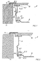
- a first embodiment of a built-in hob according to the invention 2 is partially shown in the installed position.
- the built-in hob 2 has a cover frame 4, a frame side part 6, a lower part 8 and a hob 10, wherein the built-in cooker 2 is box-shaped and the upper part are substantially formed by the hob 10 and the bottom substantially through the lower part 8.
- the cover frame 4 and the frame side member 6 are formed circumferentially and surround the lower part 8 and the hob 10 at the end faces, wherein the cover frame 4 in the installed position of the built-in hob 2, the transition region between a countertop 11 and built into an opening in the countertop 11
- Built-in hob 2 covers upwards.
- the internal clear dimensions of the cover frame 4 essentially correspond to the outermost external dimensions of the bottom part 8 relative to their expansion directions extending substantially parallel to the cooking hob 10, see FIG. 1.
- the frame side member 6 is composed of four individual segments of uniform cross section. In principle, the material and the production method for the individual segments can be selected within wide suitable limits.
- the individual segments are made of an aluminum extruded profile.
- the individual segments abut each other in the corner regions of the built-in hob 2.
- the individual segments of the frame side part 6 have at the hob 10 facing the upper end respectively a first and a second leg 6.1 and 6.2 and at the lower part 8 facing the lower end of a third leg 6.3.
- first and second legs 6.1 and 6.2 formed as grooves further recesses 6.1.1 and 6.2.1 are arranged in which formed as an adhesive in the Fig. Not shown first and second fastening means are arranged.
- the individual segments of the frame side member 6 are firmly connected both to the cover frame 4 as well as to the hob 10.
- the walls of the further recesses 6.1.1, 6.2.1 as from the the cover frame 4 and the hob 10 facing base surface of the formed first and second leg 6.1, 6.2 outstanding contact elements. This results in line-like contact surfaces between the frame side part 6 and the cover frame 4 and the hob 10, so that in the assembly of the built-in hob according to the invention 2 alignment of the aforementioned components 4, 6 and 10 to each other with sufficient accuracy in a simple manner.
- the third leg 6.3 of each segment has several holes distributed over the length of the segment.
- the substantially plate-shaped lower part 8 has, in the assembled state of the built-in cooking trough 2, further holes facing the holes.
- the lower part 8 In the assembled state of the built-in hob 2, the lower part 8 by means of commercially available screws 12, which engage through the other holes and into the holes, releasably connected to the individual segments of the frame side member 6.
- the cover frame 4 and the lower part 8 in material and form can be selected within wide suitable limits.
- the cover frame 4 and the lower part 8 are made in the present embodiment of a stainless steel plate.
- the hob 10 is further formed as a glass ceramic plate.
- the assembled built-in hob 2 can be inserted in an opening of the worktop 11 in a manner known to those skilled in the art.
- a plurality of clamping springs 16 are arranged distributed over the circumference of the surface of the worktop 11, which cooperate with a formed on each segment of the frame side member 6 projection 6.4.
- the built-in cooker 2 engages with the projections 6.4 in the insertion direction behind the clamping springs 16 a.
- the built-in cooker 2 is supported with the cover frame 4 and the first leg 6.1 of the frame side member 6 on the top of the worktop 11.
- the segments of the frame side part 6 have at their end facing the lower part 8 a further projection 6.5 and a modified third leg 6.3.
- the modified third leg 6.3 is formed with two arms, wherein the two arms are substantially parallel to each other.
- a recess 6.6 is formed on the individual segments, in which engages the edge of the lower part 8 in the assembled state of the built-in cook cavity 2 and with the recess 6.6 or the segments of the frame side part 6 locked.
- the further projection 6.5 has a run-on slope 6.5.1.
- a receptacle 6.7 is designed for a further screw between the two arms of the modified third leg 6.3.
- the recording 6.7 in nature, shape and size within wide suitable limits selectable.
- the receptacle 6.7 is formed open on one side, since the segments of the frame side part 6 of the second embodiment are also made of an aluminum extruded profile.
- the four individual segments of the frame side member 6 are made.
- the aluminum extruded profile is cut to length and the individual segments mitred and the third leg 6.3 provided with the holes for receiving the screws 12, see Fig. 4th
- the cover frame 4 is, based on the installation position of the built-in hob 2, placed with its visible side down on a flat surface, see Fig. 5.
- the designed as a glass ceramic hob 10 is also placed with the visible side down on the cover frame 4, aligned and Deck frame 4 and hob 10 are fixed in their relative position to each other, for example by a weight placed on the hob 10.
- silicone adhesive On the circumferential edge surface of the hob 10 is applied silicone adhesive.
- silicone adhesive is introduced in the formed as grooves further recesses 6.1.1 and 6.2.1 of the individual segments of the frame side member 6, of which in Fig. 5, only the further recess 6.2.1 is shown.
- the individual segments are pressed with the first and second legs 6.1 and 6.2, in which the filled with silicone adhesive grooves 6.1.1 and 6.2.1, against the cover frame 4 and against the hob 10 until the individual segments of the frame side part 6 with the base frame of the first and / or the second leg 6.1, 6.2 protruding contact elements facing the cover frame 4 or the hob 10 abut against the cover frame 4 or the hob 10.
- the relative positions of the individual segments to the cover frame 4 and the hob 10 are fixed.
- the lower part 8 is placed on the third leg 6.3, not shown in FIG. 6, of the frame segments 6 formed from the individual segments and further holes or holes arranged in the lower part 8 and on the third leg 6.3 screwed in Fig. 6, not shown screws 12 fixedly connected to the frame side member 6, see Fig. 6.
- the invention is not limited to the aforementioned embodiments.
Landscapes
- Engineering & Computer Science (AREA)
- Chemical & Material Sciences (AREA)
- Combustion & Propulsion (AREA)
- Mechanical Engineering (AREA)
- General Engineering & Computer Science (AREA)
- Induction Heating Cooking Devices (AREA)
- Combinations Of Kitchen Furniture (AREA)
- Electric Clocks (AREA)
- Mechanical Coupling Of Light Guides (AREA)
- Electric Stoves And Ranges (AREA)
Claims (10)
- Plaque de cuisson pour montage encastré, dont la partie supérieure est formée pour l'essentiel par un plan de cuisson (10), notamment une plaque en vitrocéramique, et dont le fond est formé pour l'essentiel par une partie inférieure (8) qui ferme vers le bas la plaque de cuisson (2) pour montage encastré, sachant que le plan de cuisson (10) et la partie inférieure (8) sont mutuellement reliés au moyen d'un châssis (6) formant pour l'essentiel les parois latérales de la plaque de cuisson (2) pour montage encastré et que le châssis (6) est réalisé en deux parties et présente un châssis de recouvrement (4) et une partie latérale de châssis (6), le châssis de recouvrement (4) recouvrant vers le haut, relativement à la position d'encastrement de la plaque de cuisson, la région de transition entre un plan de travail (11) et la plaque de cuisson (2) qui peut y être encastrée, et les dimensions intérieures de passage du châssis de recouvrement (4) correspondant pour l'essentiel aux dimensions les plus extérieures de la partie inférieure (8), concernant leurs directions de développement s'étendant essentiellement parallèlement au plan de cuisson (10), et le plan de cuisson (10) et la partie inférieure (8) étant mutuellement reliés au moyen de la partie latérale de châssis (6), sachant que la partie latérale de châssis (6) présente une première branche (6.1) et est reliée au châssis de recouvrement (4) par l'intermédiaire d'un premier moyen de fixation disposé sur la première branche (6.1) et au plan de cuisson (10) par l'intermédiaire d'un deuxième moyen de fixation, le premier et/ou le deuxième moyen de fixation étant une colle,
caractérisée en ce que la partie latérale de châssis (6) présente une deuxième branche (6.2) sur laquelle est disposé le deuxième moyen de fixation, et en ce que la première et/ou la deuxième branche (6.1, 6.2) de la partie latérale de châssis (6) présentent un renfoncement supplémentaire (6.1.1, 6.2.1) pour recevoir la colle. - Plaque de cuisson (2) pour montage encastré selon la revendication 1, caractérisée en ce que les parois du renfoncement supplémentaire (6.1.1, 6.2.1) sont réalisées sous la forme d'éléments d'application dépassant hors de la surface de base de la première et/ou de la deuxième branche (6.1, 6.2) qui est tournée respectivement vers le châssis de recouvrement (4) ou le plan de cuisson (10).
- Plaque de cuisson (2) pour montage encastré selon la revendication 1 ou 2, caractérisée en ce que la partie latérale de châssis (6) présente une troisième branche (6.3) et est reliée à la partie inférieure (8) au moyen d'une vis (12) disposée sur la troisième branche (6.3).
- Plaque de cuisson (2) pour montage encastré selon la revendication 1 ou 2, caractérisée en ce que la partie latérale de châssis (6) présente un renfoncement (6.6), et le bord de la partie inférieure (8) est enclenché dans le renfoncement (6.6).
- Plaque de cuisson (2) pour montage encastré selon au moins une des revendications 1 à 4, caractérisée en ce que la partie inférieure (8) est réalisée essentiellement en forme de plaque.
- Plaque de cuisson (2) pour montage encastré selon au moins une des revendications 1 à 5, caractérisée en ce que la partie latérale de châssis (6) est réalisée en plusieurs parties, les segments individuels étant réalisés sous la forme de profilés extrudés de section standard.
- Plaque de cuisson (2) pour montage encastré selon la revendication 6, caractérisée en ce que les segments individuels sont reliés aux segments respectivement voisins par des liaisons vissées.
- Procédé de fabrication d'une plaque de cuisson (2) pour montage encastré selon au moins une des revendications 1 à 7, caractérisé en ce que le châssis de recouvrement (4) et la partie inférieure (8) sont fabriqués à partir d'une unique plaque, le châssis de recouvrement (4) étant formé à partir de la région de bord de la plaque et la partie inférieure (8) à partir de l'intérieur de la plaque, et le châssis de recouvrement (4) et la partie inférieure (8) étant séparés l'un de l'autre.
- Procédé selon la revendication 8, caractérisé en ce que le châssis de recouvrement (4) et la partie inférieure (8) sont fabriqués en une unique étape de procédé.
- Procédé selon la revendication 9, caractérisé en ce que l'étape de procédé est réalisée sous la forme d'une opération de pressage.
Applications Claiming Priority (2)
| Application Number | Priority Date | Filing Date | Title |
|---|---|---|---|
| DE10341847A DE10341847B4 (de) | 2003-09-09 | 2003-09-09 | Einbaukochmulde |
| DE10341847 | 2003-09-09 |
Publications (2)
| Publication Number | Publication Date |
|---|---|
| EP1515092A1 EP1515092A1 (fr) | 2005-03-16 |
| EP1515092B1 true EP1515092B1 (fr) | 2007-10-17 |
Family
ID=34129741
Family Applications (1)
| Application Number | Title | Priority Date | Filing Date |
|---|---|---|---|
| EP04019654A Expired - Lifetime EP1515092B1 (fr) | 2003-09-09 | 2004-08-19 | Plaque de cuisson pour montage encastré |
Country Status (3)
| Country | Link |
|---|---|
| EP (1) | EP1515092B1 (fr) |
| AT (1) | ATE376153T1 (fr) |
| DE (2) | DE10341847B4 (fr) |
Families Citing this family (19)
| Publication number | Priority date | Publication date | Assignee | Title |
|---|---|---|---|---|
| DE102004048352B4 (de) * | 2004-10-01 | 2010-05-12 | Teka Küchentechnik GmbH | Haltevorrichtung, ausgebildet zur Halterung einer Kochplatte aus Glaskeramik eines Kochfeldes |
| DE102005042526A1 (de) * | 2005-09-07 | 2007-03-08 | BSH Bosch und Siemens Hausgeräte GmbH | Kochmulde |
| CN101821552B (zh) * | 2007-10-12 | 2013-06-12 | Bsh博施及西门子家用器具有限公司 | 烹饪炉盘,尤其燃气烹饪炉盘 |
| DE102007055312A1 (de) | 2007-11-20 | 2009-05-28 | BSH Bosch und Siemens Hausgeräte GmbH | Anordnung mit einem Kochfeld und einer Arbeitsplatte |
| EP2110608B1 (fr) * | 2008-04-18 | 2020-04-01 | Electrolux Home Products Corporation N.V. | Plaque de cuisson avec cadre stylique |
| EP2418427A1 (fr) * | 2008-04-18 | 2012-02-15 | Electrolux Home Products Corporation N.V. | Plaque de cuisson avec élément de fixation d'un seul tenant et élément de fixation d'un seul tenant pour plaque de cuisson |
| ES2345313B1 (es) * | 2008-06-04 | 2011-07-18 | Bsh Electrodomesticos España, S.A. | Procedimiento para la fabricacion de un campo de coccion y campo de coccion. |
| EP2144009B1 (fr) * | 2008-07-09 | 2010-06-16 | Electrolux Home Products Corporation N.V. | Élément de fixation d'un seul tenant pour plaque de cuisson et plaque de cuisson dotée d'éléments de fixation d'un seul tenant |
| DE102008042670B4 (de) * | 2008-10-08 | 2021-06-02 | BSH Hausgeräte GmbH | Hausgeräterahmen |
| ES2401839T3 (es) | 2009-05-02 | 2013-04-24 | Electrolux Home Products Corporation N.V. | Placa de cocción con elemento de protección |
| EP2378207B1 (fr) * | 2010-03-31 | 2017-05-10 | Electrolux Home Products Corporation N.V. | Agencement de cuisine |
| DE102010038807A1 (de) * | 2010-08-03 | 2012-02-09 | BSH Bosch und Siemens Hausgeräte GmbH | Befestigungselement für den Einbau eines Kochfeldes in eine Arbeitsplatte |
| EP2602556A3 (fr) * | 2011-12-07 | 2014-02-26 | BSH Bosch und Siemens Hausgeräte GmbH | Dispositif de plan de cuisson |
| DE102012215089A1 (de) * | 2012-08-24 | 2014-02-27 | Blanco Gmbh + Co Kg | Einbaugerät zum Einbau in eine Arbeitsplatte |
| DE102013206282A1 (de) * | 2013-04-10 | 2014-10-16 | E.G.O. Elektro-Gerätebau GmbH | Kochfeld und Verfahren zur Montage eines Kochfelds |
| EP2884820B1 (fr) * | 2013-12-16 | 2020-04-15 | BSH Hausgeräte GmbH | Dispositif de plaque de cuisson |
| DE102020201963A1 (de) | 2020-02-17 | 2021-08-19 | E.G.O. Elektro-Gerätebau GmbH | Kochfeld und Anordnung eines solchen Kochfelds in einer Arbeitsplatte |
| CN111750391A (zh) * | 2020-06-22 | 2020-10-09 | 广东美的厨房电器制造有限公司 | 嵌入式烤箱 |
| WO2025014435A1 (fr) * | 2023-07-11 | 2025-01-16 | Mamur Teknoloji Sistemleri San. A.S. | Plaque de cuisson dotée d'une plaque de support recouverte par un élément de protection |
Family Cites Families (7)
| Publication number | Priority date | Publication date | Assignee | Title |
|---|---|---|---|---|
| DE19637784C1 (de) * | 1996-09-17 | 1997-10-16 | Schott Glaswerke | Halterung für eine Kochfläche |
| DE7418347U (de) * | 1974-05-27 | 1975-12-04 | Bosch Siemens Hausgeraete Gmbh | Halterung fuer stell- oder traegerplatten aus glas |
| DE7718108U1 (de) * | 1977-06-08 | 1977-09-22 | Imperial-Werke Gmbh, 4980 Buende | Einbau-kochmulde mit einer glaskeramik- kochplatte |
| DE4329956C2 (de) * | 1993-09-04 | 1996-08-14 | Schott Glaswerke | Anordnung zur Halterung eines Einbaukochfeldes |
| DE4434821C2 (de) * | 1994-09-29 | 1997-12-11 | Schott Glaswerke | Anordnung zur Montage und Halterung eines Einbaukochfeldes |
| DE19604234A1 (de) * | 1996-01-29 | 1997-08-14 | Belzig Elektrowaerme Gmbh | Einbaukochfeld |
| DE19854228B4 (de) * | 1998-11-24 | 2007-09-27 | BSH Bosch und Siemens Hausgeräte GmbH | Kochfeld mit Montagerahmen in Biegetechnik |
-
2003
- 2003-09-09 DE DE10341847A patent/DE10341847B4/de not_active Expired - Fee Related
-
2004
- 2004-08-19 DE DE502004005249T patent/DE502004005249D1/de not_active Expired - Lifetime
- 2004-08-19 AT AT04019654T patent/ATE376153T1/de not_active IP Right Cessation
- 2004-08-19 EP EP04019654A patent/EP1515092B1/fr not_active Expired - Lifetime
Also Published As
| Publication number | Publication date |
|---|---|
| ATE376153T1 (de) | 2007-11-15 |
| DE10341847A1 (de) | 2005-04-28 |
| DE502004005249D1 (de) | 2007-11-29 |
| EP1515092A1 (fr) | 2005-03-16 |
| DE10341847B4 (de) | 2007-12-27 |
Similar Documents
| Publication | Publication Date | Title |
|---|---|---|
| DE10341847B4 (de) | Einbaukochmulde | |
| DE4434821C2 (de) | Anordnung zur Montage und Halterung eines Einbaukochfeldes | |
| EP0643270B1 (fr) | Dispositif de support de plaques de cuisson encastrables | |
| EP1697596B1 (fr) | Evier | |
| DE2818300A1 (de) | Bausatz zur wenigstens teilweisen veraenderung der form des daches eines kraftwagens | |
| EP0666425B1 (fr) | Assemblage de supports profilés | |
| DE10051126A1 (de) | Hydraulikblock mit daran befestigtem Anbauteil | |
| EP1045153B1 (fr) | Dispositif de fixation de tôles | |
| EP3837401B1 (fr) | Élément de liaison pour la fixation d'un évier sur un plateau de travail | |
| DE102007017116A1 (de) | Verfahren zur Herstellung eines Spülbehälters, insbesondere für eine Geschirrspülmaschine | |
| DE2850654A1 (de) | Basiseinheit fuer den sitzteil oder den lehnenteil eines sitzes, insbesondere eines fahrzeugsitzes, und verfahren zur herstellung desselben | |
| DE202008004148U1 (de) | Möbelkorpus | |
| AT393600B (de) | Schublade | |
| DE202008004145U1 (de) | Möbelkorpus | |
| DE20103473U1 (de) | Spülebecken | |
| DE562614C (de) | Zahnrad aus Pressmasse | |
| DE202021101300U1 (de) | Befestigungsplattenanordnung | |
| WO2001039571A1 (fr) | Bloc hydraulique dote d'une piece rapportee fixee sur ledit bloc | |
| DE102009018132A1 (de) | Halteklammer für Holzverpackungen und Verfahren zum Herstellen einer Halteklammer | |
| DE102013021932A1 (de) | Verbindung von Rotorkernpaket und Läuferwelle an einer elektrischen Maschine | |
| DE20214356U1 (de) | Verbindung zwischen einer Scheibe und einer Stange | |
| EP2606284B1 (fr) | Hotte aspirante | |
| EP3574802B1 (fr) | Paroi pour un meuble ou partie de meuble | |
| WO2019238491A1 (fr) | Châssis pour tiroir | |
| EP3599137B1 (fr) | Système de fixation pour véhicule automobile |
Legal Events
| Date | Code | Title | Description |
|---|---|---|---|
| PUAI | Public reference made under article 153(3) epc to a published international application that has entered the european phase |
Free format text: ORIGINAL CODE: 0009012 |
|
| AK | Designated contracting states |
Kind code of ref document: A1 Designated state(s): AT BE BG CH CY CZ DE DK EE ES FI FR GB GR HU IE IT LI LU MC NL PL PT RO SE SI SK TR |
|
| AX | Request for extension of the european patent |
Extension state: AL HR LT LV MK |
|
| 17P | Request for examination filed |
Effective date: 20050806 |
|
| AKX | Designation fees paid |
Designated state(s): AT BE BG CH CY CZ DE DK EE ES FI FR GB GR HU IE IT LI LU MC NL PL PT RO SE SI SK TR |
|
| GRAP | Despatch of communication of intention to grant a patent |
Free format text: ORIGINAL CODE: EPIDOSNIGR1 |
|
| GRAS | Grant fee paid |
Free format text: ORIGINAL CODE: EPIDOSNIGR3 |
|
| GRAA | (expected) grant |
Free format text: ORIGINAL CODE: 0009210 |
|
| AK | Designated contracting states |
Kind code of ref document: B1 Designated state(s): AT BE BG CH CY CZ DE DK EE ES FI FR GB GR HU IE IT LI LU MC NL PL PT RO SE SI SK TR |
|
| REG | Reference to a national code |
Ref country code: GB Ref legal event code: FG4D Free format text: NOT ENGLISH |
|
| REG | Reference to a national code |
Ref country code: CH Ref legal event code: EP |
|
| REG | Reference to a national code |
Ref country code: IE Ref legal event code: FG4D Free format text: LANGUAGE OF EP DOCUMENT: GERMAN |
|
| REF | Corresponds to: |
Ref document number: 502004005249 Country of ref document: DE Date of ref document: 20071129 Kind code of ref document: P |
|
| GBT | Gb: translation of ep patent filed (gb section 77(6)(a)/1977) | ||
| REG | Reference to a national code |
Ref country code: GB Ref legal event code: 746 Effective date: 20080201 |
|
| NLV1 | Nl: lapsed or annulled due to failure to fulfill the requirements of art. 29p and 29m of the patents act | ||
| PG25 | Lapsed in a contracting state [announced via postgrant information from national office to epo] |
Ref country code: NL Free format text: LAPSE BECAUSE OF FAILURE TO SUBMIT A TRANSLATION OF THE DESCRIPTION OR TO PAY THE FEE WITHIN THE PRESCRIBED TIME-LIMIT Effective date: 20071017 Ref country code: ES Free format text: LAPSE BECAUSE OF FAILURE TO SUBMIT A TRANSLATION OF THE DESCRIPTION OR TO PAY THE FEE WITHIN THE PRESCRIBED TIME-LIMIT Effective date: 20080128 Ref country code: SE Free format text: LAPSE BECAUSE OF FAILURE TO SUBMIT A TRANSLATION OF THE DESCRIPTION OR TO PAY THE FEE WITHIN THE PRESCRIBED TIME-LIMIT Effective date: 20080117 |
|
| PG25 | Lapsed in a contracting state [announced via postgrant information from national office to epo] |
Ref country code: PL Free format text: LAPSE BECAUSE OF FAILURE TO SUBMIT A TRANSLATION OF THE DESCRIPTION OR TO PAY THE FEE WITHIN THE PRESCRIBED TIME-LIMIT Effective date: 20071017 Ref country code: PT Free format text: LAPSE BECAUSE OF FAILURE TO SUBMIT A TRANSLATION OF THE DESCRIPTION OR TO PAY THE FEE WITHIN THE PRESCRIBED TIME-LIMIT Effective date: 20080317 Ref country code: BG Free format text: LAPSE BECAUSE OF FAILURE TO SUBMIT A TRANSLATION OF THE DESCRIPTION OR TO PAY THE FEE WITHIN THE PRESCRIBED TIME-LIMIT Effective date: 20080117 Ref country code: SI Free format text: LAPSE BECAUSE OF FAILURE TO SUBMIT A TRANSLATION OF THE DESCRIPTION OR TO PAY THE FEE WITHIN THE PRESCRIBED TIME-LIMIT Effective date: 20071017 |
|
| REG | Reference to a national code |
Ref country code: IE Ref legal event code: FD4D |
|
| ET | Fr: translation filed | ||
| PG25 | Lapsed in a contracting state [announced via postgrant information from national office to epo] |
Ref country code: DK Free format text: LAPSE BECAUSE OF FAILURE TO SUBMIT A TRANSLATION OF THE DESCRIPTION OR TO PAY THE FEE WITHIN THE PRESCRIBED TIME-LIMIT Effective date: 20071017 Ref country code: CZ Free format text: LAPSE BECAUSE OF FAILURE TO SUBMIT A TRANSLATION OF THE DESCRIPTION OR TO PAY THE FEE WITHIN THE PRESCRIBED TIME-LIMIT Effective date: 20071017 |
|
| PLBE | No opposition filed within time limit |
Free format text: ORIGINAL CODE: 0009261 |
|
| STAA | Information on the status of an ep patent application or granted ep patent |
Free format text: STATUS: NO OPPOSITION FILED WITHIN TIME LIMIT |
|
| PG25 | Lapsed in a contracting state [announced via postgrant information from national office to epo] |
Ref country code: SK Free format text: LAPSE BECAUSE OF FAILURE TO SUBMIT A TRANSLATION OF THE DESCRIPTION OR TO PAY THE FEE WITHIN THE PRESCRIBED TIME-LIMIT Effective date: 20071017 Ref country code: RO Free format text: LAPSE BECAUSE OF FAILURE TO SUBMIT A TRANSLATION OF THE DESCRIPTION OR TO PAY THE FEE WITHIN THE PRESCRIBED TIME-LIMIT Effective date: 20071017 |
|
| 26N | No opposition filed |
Effective date: 20080718 |
|
| PG25 | Lapsed in a contracting state [announced via postgrant information from national office to epo] |
Ref country code: IE Free format text: LAPSE BECAUSE OF FAILURE TO SUBMIT A TRANSLATION OF THE DESCRIPTION OR TO PAY THE FEE WITHIN THE PRESCRIBED TIME-LIMIT Effective date: 20071017 |
|
| PG25 | Lapsed in a contracting state [announced via postgrant information from national office to epo] |
Ref country code: GR Free format text: LAPSE BECAUSE OF FAILURE TO SUBMIT A TRANSLATION OF THE DESCRIPTION OR TO PAY THE FEE WITHIN THE PRESCRIBED TIME-LIMIT Effective date: 20080118 |
|
| PG25 | Lapsed in a contracting state [announced via postgrant information from national office to epo] |
Ref country code: FI Free format text: LAPSE BECAUSE OF FAILURE TO SUBMIT A TRANSLATION OF THE DESCRIPTION OR TO PAY THE FEE WITHIN THE PRESCRIBED TIME-LIMIT Effective date: 20071017 |
|
| PG25 | Lapsed in a contracting state [announced via postgrant information from national office to epo] |
Ref country code: MC Free format text: LAPSE BECAUSE OF NON-PAYMENT OF DUE FEES Effective date: 20080831 |
|
| REG | Reference to a national code |
Ref country code: CH Ref legal event code: PL |
|
| PG25 | Lapsed in a contracting state [announced via postgrant information from national office to epo] |
Ref country code: EE Free format text: LAPSE BECAUSE OF FAILURE TO SUBMIT A TRANSLATION OF THE DESCRIPTION OR TO PAY THE FEE WITHIN THE PRESCRIBED TIME-LIMIT Effective date: 20071017 |
|
| PG25 | Lapsed in a contracting state [announced via postgrant information from national office to epo] |
Ref country code: CH Free format text: LAPSE BECAUSE OF NON-PAYMENT OF DUE FEES Effective date: 20080831 Ref country code: LI Free format text: LAPSE BECAUSE OF NON-PAYMENT OF DUE FEES Effective date: 20080831 |
|
| PG25 | Lapsed in a contracting state [announced via postgrant information from national office to epo] |
Ref country code: CY Free format text: LAPSE BECAUSE OF FAILURE TO SUBMIT A TRANSLATION OF THE DESCRIPTION OR TO PAY THE FEE WITHIN THE PRESCRIBED TIME-LIMIT Effective date: 20071017 Ref country code: BE Free format text: LAPSE BECAUSE OF NON-PAYMENT OF DUE FEES Effective date: 20080831 |
|
| PG25 | Lapsed in a contracting state [announced via postgrant information from national office to epo] |
Ref country code: AT Free format text: LAPSE BECAUSE OF NON-PAYMENT OF DUE FEES Effective date: 20080819 |
|
| PG25 | Lapsed in a contracting state [announced via postgrant information from national office to epo] |
Ref country code: HU Free format text: LAPSE BECAUSE OF FAILURE TO SUBMIT A TRANSLATION OF THE DESCRIPTION OR TO PAY THE FEE WITHIN THE PRESCRIBED TIME-LIMIT Effective date: 20080418 Ref country code: LU Free format text: LAPSE BECAUSE OF NON-PAYMENT OF DUE FEES Effective date: 20080819 |
|
| PG25 | Lapsed in a contracting state [announced via postgrant information from national office to epo] |
Ref country code: TR Free format text: LAPSE BECAUSE OF FAILURE TO SUBMIT A TRANSLATION OF THE DESCRIPTION OR TO PAY THE FEE WITHIN THE PRESCRIBED TIME-LIMIT Effective date: 20071017 |
|
| REG | Reference to a national code |
Ref country code: FR Ref legal event code: PLFP Year of fee payment: 13 |
|
| REG | Reference to a national code |
Ref country code: FR Ref legal event code: PLFP Year of fee payment: 14 |
|
| REG | Reference to a national code |
Ref country code: FR Ref legal event code: PLFP Year of fee payment: 15 |
|
| PGFP | Annual fee paid to national office [announced via postgrant information from national office to epo] |
Ref country code: IT Payment date: 20220819 Year of fee payment: 19 Ref country code: GB Payment date: 20220823 Year of fee payment: 19 Ref country code: DE Payment date: 20220831 Year of fee payment: 19 |
|
| PGFP | Annual fee paid to national office [announced via postgrant information from national office to epo] |
Ref country code: FR Payment date: 20220824 Year of fee payment: 19 |
|
| REG | Reference to a national code |
Ref country code: DE Ref legal event code: R119 Ref document number: 502004005249 Country of ref document: DE |
|
| GBPC | Gb: european patent ceased through non-payment of renewal fee |
Effective date: 20230819 |
|
| PG25 | Lapsed in a contracting state [announced via postgrant information from national office to epo] |
Ref country code: GB Free format text: LAPSE BECAUSE OF NON-PAYMENT OF DUE FEES Effective date: 20230819 |
|
| PG25 | Lapsed in a contracting state [announced via postgrant information from national office to epo] |
Ref country code: IT Free format text: LAPSE BECAUSE OF NON-PAYMENT OF DUE FEES Effective date: 20230819 Ref country code: GB Free format text: LAPSE BECAUSE OF NON-PAYMENT OF DUE FEES Effective date: 20230819 Ref country code: FR Free format text: LAPSE BECAUSE OF NON-PAYMENT OF DUE FEES Effective date: 20230831 Ref country code: DE Free format text: LAPSE BECAUSE OF NON-PAYMENT OF DUE FEES Effective date: 20240301 |