EP1515082A1 - Eine Vorrichtung um Fluide zu messen, zum Beispiel für Textilfabriken - Google Patents
Eine Vorrichtung um Fluide zu messen, zum Beispiel für Textilfabriken Download PDFInfo
- Publication number
- EP1515082A1 EP1515082A1 EP03425584A EP03425584A EP1515082A1 EP 1515082 A1 EP1515082 A1 EP 1515082A1 EP 03425584 A EP03425584 A EP 03425584A EP 03425584 A EP03425584 A EP 03425584A EP 1515082 A1 EP1515082 A1 EP 1515082A1
- Authority
- EP
- European Patent Office
- Prior art keywords
- manifold
- fluid
- syringe
- valve
- metering
- Prior art date
- Legal status (The legal status is an assumption and is not a legal conclusion. Google has not performed a legal analysis and makes no representation as to the accuracy of the status listed.)
- Granted
Links
- 239000012530 fluid Substances 0.000 title claims abstract description 46
- 239000004753 textile Substances 0.000 title abstract description 7
- 238000004891 communication Methods 0.000 claims abstract description 14
- 239000007788 liquid Substances 0.000 claims description 6
- 230000004913 activation Effects 0.000 claims 1
- 238000007599 discharging Methods 0.000 claims 1
- 238000005086 pumping Methods 0.000 claims 1
- 239000000047 product Substances 0.000 description 24
- XLYOFNOQVPJJNP-UHFFFAOYSA-N water Substances O XLYOFNOQVPJJNP-UHFFFAOYSA-N 0.000 description 20
- 239000000243 solution Substances 0.000 description 6
- 238000005406 washing Methods 0.000 description 6
- 238000004043 dyeing Methods 0.000 description 5
- 230000008901 benefit Effects 0.000 description 4
- 238000004519 manufacturing process Methods 0.000 description 4
- 238000000034 method Methods 0.000 description 4
- 238000011144 upstream manufacturing Methods 0.000 description 3
- 238000010586 diagram Methods 0.000 description 2
- 238000011010 flushing procedure Methods 0.000 description 2
- 230000007246 mechanism Effects 0.000 description 2
- 230000008569 process Effects 0.000 description 2
- 239000004902 Softening Agent Substances 0.000 description 1
- 239000003929 acidic solution Substances 0.000 description 1
- 230000002378 acidificating effect Effects 0.000 description 1
- 239000003637 basic solution Substances 0.000 description 1
- 239000000975 dye Substances 0.000 description 1
- 230000000694 effects Effects 0.000 description 1
- 239000000839 emulsion Substances 0.000 description 1
- 230000002401 inhibitory effect Effects 0.000 description 1
- 239000012263 liquid product Substances 0.000 description 1
- 239000000344 soap Substances 0.000 description 1
- 239000000126 substance Substances 0.000 description 1
- 230000007704 transition Effects 0.000 description 1
Images




Classifications
-
- F—MECHANICAL ENGINEERING; LIGHTING; HEATING; WEAPONS; BLASTING
- F17—STORING OR DISTRIBUTING GASES OR LIQUIDS
- F17D—PIPE-LINE SYSTEMS; PIPE-LINES
- F17D3/00—Arrangements for supervising or controlling working operations
- F17D3/10—Arrangements for supervising or controlling working operations for taking out the product in the line
-
- G—PHYSICS
- G01—MEASURING; TESTING
- G01F—MEASURING VOLUME, VOLUME FLOW, MASS FLOW OR LIQUID LEVEL; METERING BY VOLUME
- G01F11/00—Apparatus requiring external operation adapted at each repeated and identical operation to measure and separate a predetermined volume of fluid or fluent solid material from a supply or container, without regard to weight, and to deliver it
- G01F11/02—Apparatus requiring external operation adapted at each repeated and identical operation to measure and separate a predetermined volume of fluid or fluent solid material from a supply or container, without regard to weight, and to deliver it with measuring chambers which expand or contract during measurement
- G01F11/021—Apparatus requiring external operation adapted at each repeated and identical operation to measure and separate a predetermined volume of fluid or fluent solid material from a supply or container, without regard to weight, and to deliver it with measuring chambers which expand or contract during measurement of the piston type
- G01F11/025—Apparatus requiring external operation adapted at each repeated and identical operation to measure and separate a predetermined volume of fluid or fluent solid material from a supply or container, without regard to weight, and to deliver it with measuring chambers which expand or contract during measurement of the piston type with manually operated pistons
- G01F11/027—Apparatus requiring external operation adapted at each repeated and identical operation to measure and separate a predetermined volume of fluid or fluent solid material from a supply or container, without regard to weight, and to deliver it with measuring chambers which expand or contract during measurement of the piston type with manually operated pistons of the syringe type
Definitions
- the present invention relates to systems for metering fluids, for example for metering dyeing products in the framework of the so-called "colour kitchens" of textile plants.
- the solutions commonly used for obtaining systems which can meter precise amounts of products and send said precisely metered amounts of products to production systems via a network of pipes are basically two.
- a first type of system is based essentially upon a technique which can be defined as gravimetric/weight-based.
- a tank is provided, which rests upon a weighing-machine that is disconnected from the delivery pipe by means of a system that can be uncoupled and has on its top part a series of valves (of a dual-stage on/off or modulating type) that meter the product.
- This system guarantees excellent precision but, in addition to usually being rather costly and slow, imposes the need for mixing the product with the carrier liquid (typically water) necessary for washing the tank.
- the carrier liquid typically water
- Another type of system is based upon volumetric techniques.
- the systems of this type are based upon the incompressibility of fluids and basically envisage the presence, within a circuit that is closed by various (inlet or outlet) valves and is always full of carrier liquid (water), of a flow meter (litre-counter), which can control and regulate entry of the product that is to be sent to the production machines.
- This system is intrinsically less precise than the one referred to previously on account of the section of passage of the valves and the performance of the litre-counter device. It presents the major advantage of enabling a considerable operating speed, of using a reduced amount of carrier liquid for conveying the product. Furthermore, it is usually more reliable and economically advantageous than the gravimetric/weight-based system.
- the main limit of the volumetric system in addition to its low precision, is represented by the impossibility of carrying out metering of small amounts. This normally entails the need for manual intervention for metering such amounts.
- the purpose of the present invention is to meet the above requirement.
- the solution described herein envisages using, in the framework of a system that may fundamentally be likened to a metering system of a volumetric type, a syringe-type metering unit that enables a rather high metering precision to be obtained, virtually similar to the one that can be achieved with the gravimetric/weight-based system.
- the solution described herein presents further advantages linked to the possibility of operating with reduced quantities of water and using compressed air for washing.
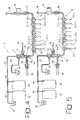
- a system such as the one designated as a whole by 10 in Figure 1 is designed for being used in a textile system, for example for controlled metering of dyeing products that are to be sent on to treatment machines, such as dyeing machines and the like.
- the solution described herein can be used for metering all the liquid products useful for textile treatment processes, both dyeing and finishing. Normally, said products are divided into three types:
- the reference number 12 designates as a whole a manifold comprising any number n of valves arranged in cascaded fashion 12.1, 12.2, 12.3, ..., 12.n of the type commonly referred to (perhaps in a not altogether appropriate way) as "three-way" valves.
- valves comprising three connection ports or openings.
- two constitute two openings (one for inlet and one for outlet) aligned with respect to one another in the general direction of flow of the fluids through the manifold in an arrangement in which:
- Each of the valves 12.1 to 12.n then has a third port connected to a respective inlet pipe 22.1, 22.2, ..., 22.n for enabling supply of a fluid product to be metered.
- each of the valves 12.1 to 12.n has a rotary distributor, which presents a general T-shaped configuration.
- the aim of the above is to enable, for each of the valves 12.1 to 12.n, at least two operating positions, namely,
- the selective actuation of the open/close element, and hence switching between the two possible operating positions described previously, is obtained by means of known means (typically by means of a fluid actuator or solenoid) according to criteria in themselves known.
- a fluid actuator or solenoid typically by means of a fluid actuator or solenoid
- the actuation mechanism can be interlocked to a programmable control unit (for example a PLC or a similar device), which is also of a known type and is designed to superintend operation of the open/close elements of all of the valves 12.1, ..., 12.n and of all the other switching elements (valves or the like) present in the system 10, as well as the valve 14, which is designed to inhibit selectively flow of the water from the litre-counter 16 to the manifold 12, and all the other valves and elements described in what follows.
- a programmable control unit for example a PLC or a similar device
- manifold 12 may be replaced by a functionally equivalent device.
- the syringe-type metering element 20 is set downstream of the manifold 12 in the water flow line starting from the litre-counter 16.
- the metering device 20 is made up of a cylindrical tubular body 24 having a proximal end 24a, which gives out into the flow pipe situated downstream of the manifold 12.
- a piston 26 Free to move, in a water-tight way, inside the cylinder 24 is a piston 26, actuated by a positioning device 28 consisting typically of an electro-mechanical actuator, or positioner.
- an electro-mechanical actuator for example, of the screw type
- a high degree of precision to be achieved in the positioning of the piston 26 inside the cylindrical body 24 of the metering device 20.
- the references numbers 30 and 32 designate two further valves basically similar to the valves 12.1 to 12.n that make up the manifold 12. In practice, the two valves 30 and 32 are arranged in cascaded fashion along the water flow pipe, starting from the manifold 12 to a distribution line designated by 34.
- valve 30 enables the flow line that goes from the manifold 12 to the distribution line 34 to be set selectively in communication (according to the criteria described in greater detail in what follows) with a compressed-air supply line 36, in which there is set a shut-off valve 38 basically similar to the shut-off valve 14 situated downstream of the litre-counter 16.
- the valve 32 enables, instead, the flow line downstream of the manifold 12 to be set in communication with a local discharge pipe 40, which comes under a container/reservoir 42 for collection and disposal.
- Set in the distribution line 34 are one or more valves 44, 46, which enable the fluid that is flowing in the distribution line 34 to be selectively deviated to one or more containers 48, 50, which have the function of user container, i.e., of a container in which the metered fluid is collected.
- reference number 52 designates a further pipe/container, which is designed to function for draining off the distribution line 34 according to the modalities described in greater detail in what follows.
- Figure 2 illustrates the typical condition of start of the metering cycle.
- an intermediate step which is advantageous for achieving proper metering, i.e., filling of the circuit comprised between the valves 14 and 30 without the presence of any air bubbles.
- the manifold 12 is set in communication with the discharge 42, causing an amount of water equal to or larger than the capacity of the manifold 12 to enter the circuit by opening the valve 14 and measuring the said amount with the litre-counter 16.
- the water-supply line (in the remainder of the present description we shall continue to assume that the solution-carrier liquid is water, but this choice is not in any way binding for the purposes of the invention) is completely full both in the stretch that extends through the manifold 12 and in the stretch into which the proximal opening 24a of the syringe-type metering device 20 gives out.
- shut-off valves 14 and 38 are in a closed position and that both of the open/close elements of the valves 30 and 32 are full of fluid, the same applying also to the local discharge line 40.
- Figure 3 refers to an operation of metering the fluid coming, for example, from the supply line 22.1 associated to the first valve 12.1 of the manifold 12. It will be appreciated that the same modalities of operation (and hence of metering) are applicable to any one of the fluids that can be supplied by means of the other lines 22.2 to 22.n.
- the fluid recalled inside the metering device 20 is usually made up of the carrier liquid (hence, water).
- the quantity of carrier fluid recalled into the metering device 20 starting from its proximal end 24a corresponds exactly to the quantity of fluid to be metered that is taken from the line 22.1.
- the next operating step represented in Figure 4 envisages that the valve 30 will be brought into the position in which the valve itself sets its inlet port in communication with its outlet port.
- the valve 12.1 is brought back into the position in which the fluid continuity of the manifold 12 is reconstituted by inhibiting communication with the supply line 22.1.
- the metering device 20 is again actuated so as to bring the piston 26 back into the position of end-of-travel, and hence expelling once again, starting from its proximal end 24a, the amount of fluid (exactly metered) previously recalled into the cylinder 24 during the step illustrated in Figure 3.
- the net effect of said operation is to bring about a rise of the fluid inside the first stretch of the distribution line 34 beyond the valve 32.
- the step of expulsion of the fluid from the metering device 20 also envisages rotation of the valve 44 or, alternatively, of an end-of-line valve (not illustrated in the drawings).
- a number of metering operations of the type described above may be concatenated, before sending the metered product to the user points, for metering amounts of product greater than the capacity of the syringe-type metering device 20 or for metering other products that are compatible with one another.
- valve 30 has the function of closing the manifold 12 so that the syringe-type metering device 20, as it moves back, will take product only from the respective open valve.
- the function of causing the distribution line to communicate with the supply of air is hence secondary in so far as the system can deliver even only with water taken from the valve 14.
- shut-off valve 14 is brought into the opening position, thus causing, as a result of the inflow of water through the line 18, the product that has previously been taken from the line 22.1 through the valve 12.1 to rise inside the distribution line 34 beyond the valve 30 (which may be referred to as "air valve” on account of its connection to the compressed-air supply line designated by 36).
- the circuit may be cleared either with water or with compressed air.
- a water buffer determined by the operating cycle, between the product and the air, with the function of flushing the pipe.
- the air valve 30 is brought into the position where it is able to set the compressed-air supply line 36 in communication, via the shut-off valve 38 brought into the opening position, with the distribution line 34.
- Figure 7 illustrates a possible subsequent operating step, in which, once the valve 30 has been brought back into the operating position that establishes fluid connection between the manifold 12 and the distribution plug 34, it is possible to proceed to flushing of the line in the machine with a water buffer pushed by the air.
- Figure 7 represents a step of transition between emptying of the line and subsequent washing of the line being discharged 52 of Figure 8. Should more washing water be required, it is possible to increase the buffer or else use just water and not compressed air.
- the step represented in Figure 8 corresponds to the operating step in which, by means of water taken from the line 18, it is possible to proceed to a complete clearing of the entire line involved in the metering phenomenon (manifold 12, proximal opening 24a of the metering device 20, valves 30 and 32, distribution line 34), causing the corresponding fluid to be discharged to the end-of-line pipe 52 through the valves 44 and 46, maintained in the condition that establishes fluid continuity between the distribution line 34 and the end of the line 52.
- the barrels 48 and 50 represent schematically the various items of user apparatus. Usually, these are connected up to a computer, which enables them to transmit the metering requirements of the system metering device that carries out metering and to deliver the products in the quantities required.
- the above system envisages creating, starting from just one line, with three-way valves, such as the valve 44 or the valve 46, sub-branches in which it is possible to distribute other user valves so as to optimize the path inside the production departments.
- three-way valves such as the valve 44 or the valve 46
- sub-branches in which it is possible to distribute other user valves so as to optimize the path inside the production departments.
- a two-way drain-off valve (not illustrated in the drawings).
- the metering cycle just described may be repeated starting from the operating position illustrated in Figure 2, along with the possibility of a free choice of the line 22.1 to 22.n from which the fluid to be metered is to be taken.
- the solution described herein enables, whilst an operation of suction/metering of a product is being performed, simultaneous completion of a previous metering operation by introducing air from the line 36 to the destinations 44, 46 or 52.
- valves 30 and 32 in themselves have secondary functions with respect to the syringe-type metering mechanism described herein.
- valves 30 and 32 set in communication the inlet for the air (valve 30) and the washing discharge (valve 32). Their main purpose is thus to optimize other functions of the system, for example to reduce the amount of water that conveys the product or to improve washing of the metering manifold.
- valve 44 or valve 46 the system described herein is able to function also by replacing the two three-way valves with just one two-way valve so as to close the circuit downstream of metering in the step of suction of the syringe-type metering device.
- valve 32 may play a role in the metering process in the case of complex configurations of the circuit, when the valves 44 and 46 representing the points using the metered amounts are numerous and located at some distance from one another.
- the valve 32 which is used in the step of pushing the fluid to the discharge 42, may moreover have the function of optimizing efficiency of the syringe, maintaining a constant pressure head.
Landscapes
- Engineering & Computer Science (AREA)
- Mechanical Engineering (AREA)
- General Engineering & Computer Science (AREA)
- Physics & Mathematics (AREA)
- Fluid Mechanics (AREA)
- General Physics & Mathematics (AREA)
- Treatment Of Fiber Materials (AREA)
- Measuring Volume Flow (AREA)
- Feeding, Discharge, Calcimining, Fusing, And Gas-Generation Devices (AREA)
- Accessories For Mixers (AREA)
- Cultivation Of Plants (AREA)
- Loading And Unloading Of Fuel Tanks Or Ships (AREA)
Priority Applications (6)
| Application Number | Priority Date | Filing Date | Title |
|---|---|---|---|
| AT03425584T ATE473393T1 (de) | 2003-09-09 | 2003-09-09 | Eine vorrichtung um fluide zu messen, zum beispiel für textilfabriken |
| DE60333290T DE60333290D1 (de) | 2003-09-09 | 2003-09-09 | Eine Vorrichtung um Fluide zu messen, zum Beispiel für Textilfabriken |
| EP03425584A EP1515082B1 (de) | 2003-09-09 | 2003-09-09 | Eine Vorrichtung um Fluide zu messen, zum Beispiel für Textilfabriken |
| CNB2004100491194A CN100338286C (zh) | 2003-09-09 | 2004-06-17 | 如用于纺织厂的计量液体的装置 |
| BRPI0402421-4A BRPI0402421B1 (pt) | 2003-09-09 | 2004-06-22 | Sistema para a medição seletiva de fluidos, adequado para uso em plantas têxteis. |
| HK05104148.8A HK1073496B (en) | 2005-05-17 | An arrangement for metering fluids, for instance for textile plants |
Applications Claiming Priority (1)
| Application Number | Priority Date | Filing Date | Title |
|---|---|---|---|
| EP03425584A EP1515082B1 (de) | 2003-09-09 | 2003-09-09 | Eine Vorrichtung um Fluide zu messen, zum Beispiel für Textilfabriken |
Publications (2)
| Publication Number | Publication Date |
|---|---|
| EP1515082A1 true EP1515082A1 (de) | 2005-03-16 |
| EP1515082B1 EP1515082B1 (de) | 2010-07-07 |
Family
ID=34130429
Family Applications (1)
| Application Number | Title | Priority Date | Filing Date |
|---|---|---|---|
| EP03425584A Expired - Lifetime EP1515082B1 (de) | 2003-09-09 | 2003-09-09 | Eine Vorrichtung um Fluide zu messen, zum Beispiel für Textilfabriken |
Country Status (5)
| Country | Link |
|---|---|
| EP (1) | EP1515082B1 (de) |
| CN (1) | CN100338286C (de) |
| AT (1) | ATE473393T1 (de) |
| BR (1) | BRPI0402421B1 (de) |
| DE (1) | DE60333290D1 (de) |
Cited By (3)
| Publication number | Priority date | Publication date | Assignee | Title |
|---|---|---|---|---|
| WO2006035274A1 (en) * | 2004-09-29 | 2006-04-06 | Nokia Corporation | Transmitting data in a wireless network |
| EP2639664A4 (de) * | 2010-11-12 | 2017-06-28 | Aurep Dos S.L. | Vorrichtung und verfahren zur messung einer nicht komprimierbaren flüssigkeit |
| CN108870080A (zh) * | 2018-05-18 | 2018-11-23 | 黎明职业大学 | 一种计量输送方法及装置 |
Families Citing this family (2)
| Publication number | Priority date | Publication date | Assignee | Title |
|---|---|---|---|---|
| CN102507908B (zh) * | 2011-11-02 | 2014-04-16 | 广州市纤维产品检测院 | 湿水处理测试仪 |
| US12310378B2 (en) | 2020-06-29 | 2025-05-27 | Jbt Marel Corporation | Produce processing dosing system |
Citations (6)
| Publication number | Priority date | Publication date | Assignee | Title |
|---|---|---|---|---|
| US4257439A (en) * | 1976-06-23 | 1981-03-24 | Bi-M Instrument Company | Apparatus for producing calibration gases suitable for analytical instrumentation |
| US4354516A (en) * | 1980-10-24 | 1982-10-19 | Ronald Newell | Automatic control valve |
| US4874014A (en) * | 1987-12-21 | 1989-10-17 | Fsi International, Inc. | Flow control manifold |
| US4917304A (en) * | 1986-12-31 | 1990-04-17 | Avanti Manufacturing Co. | Automatic controller for injection of additives into irrigation water |
| US5135174A (en) * | 1990-11-08 | 1992-08-04 | Chaplinsky Michael J | Automatic micro-feeding system for applying multiple independent plant nutrients to irrigation systems |
| US5616822A (en) * | 1992-11-19 | 1997-04-01 | The Secretary Of State For Defence In Her Britannic Majesty's Government Of The United Kingdom Of Great Britain And Northern Ireland, A British Corporation Sole | Calibration systems |
Family Cites Families (1)
| Publication number | Priority date | Publication date | Assignee | Title |
|---|---|---|---|---|
| IT1234720B (it) * | 1989-08-29 | 1992-05-26 | Color Service Srl | Impianto di preparazione e distribuzione di soluzioni coloranti nelle tintorie |
-
2003
- 2003-09-09 EP EP03425584A patent/EP1515082B1/de not_active Expired - Lifetime
- 2003-09-09 DE DE60333290T patent/DE60333290D1/de not_active Expired - Lifetime
- 2003-09-09 AT AT03425584T patent/ATE473393T1/de not_active IP Right Cessation
-
2004
- 2004-06-17 CN CNB2004100491194A patent/CN100338286C/zh not_active Expired - Lifetime
- 2004-06-22 BR BRPI0402421-4A patent/BRPI0402421B1/pt not_active IP Right Cessation
Patent Citations (6)
| Publication number | Priority date | Publication date | Assignee | Title |
|---|---|---|---|---|
| US4257439A (en) * | 1976-06-23 | 1981-03-24 | Bi-M Instrument Company | Apparatus for producing calibration gases suitable for analytical instrumentation |
| US4354516A (en) * | 1980-10-24 | 1982-10-19 | Ronald Newell | Automatic control valve |
| US4917304A (en) * | 1986-12-31 | 1990-04-17 | Avanti Manufacturing Co. | Automatic controller for injection of additives into irrigation water |
| US4874014A (en) * | 1987-12-21 | 1989-10-17 | Fsi International, Inc. | Flow control manifold |
| US5135174A (en) * | 1990-11-08 | 1992-08-04 | Chaplinsky Michael J | Automatic micro-feeding system for applying multiple independent plant nutrients to irrigation systems |
| US5616822A (en) * | 1992-11-19 | 1997-04-01 | The Secretary Of State For Defence In Her Britannic Majesty's Government Of The United Kingdom Of Great Britain And Northern Ireland, A British Corporation Sole | Calibration systems |
Cited By (3)
| Publication number | Priority date | Publication date | Assignee | Title |
|---|---|---|---|---|
| WO2006035274A1 (en) * | 2004-09-29 | 2006-04-06 | Nokia Corporation | Transmitting data in a wireless network |
| EP2639664A4 (de) * | 2010-11-12 | 2017-06-28 | Aurep Dos S.L. | Vorrichtung und verfahren zur messung einer nicht komprimierbaren flüssigkeit |
| CN108870080A (zh) * | 2018-05-18 | 2018-11-23 | 黎明职业大学 | 一种计量输送方法及装置 |
Also Published As
| Publication number | Publication date |
|---|---|
| EP1515082B1 (de) | 2010-07-07 |
| CN1594707A (zh) | 2005-03-16 |
| CN100338286C (zh) | 2007-09-19 |
| HK1073496A1 (en) | 2005-10-07 |
| BRPI0402421A (pt) | 2005-05-24 |
| BRPI0402421B1 (pt) | 2014-12-30 |
| DE60333290D1 (de) | 2010-08-19 |
| ATE473393T1 (de) | 2010-07-15 |
Similar Documents
| Publication | Publication Date | Title |
|---|---|---|
| CN101007661B (zh) | 水净化系统及方法 | |
| US3814289A (en) | Multiple component mixing device | |
| US3213873A (en) | Self-powered fluid treater | |
| EP1515082B1 (de) | Eine Vorrichtung um Fluide zu messen, zum Beispiel für Textilfabriken | |
| CN111828843B (zh) | 一种粘稠液体分流阀及其粘稠液体输送装置与方法 | |
| CN204433102U (zh) | 用于将灌装产品计量注入待灌注容器的装置 | |
| CN103562691B (zh) | 向流体输送装置精确输送受控量的粘性流体的系统和方法 | |
| CN101487565B (zh) | 流体在线计量配送系统 | |
| JPH11240010A (ja) | ポリウレタン成形体を製造するための方法および装置 | |
| HK1073496B (en) | An arrangement for metering fluids, for instance for textile plants | |
| US3712335A (en) | Car wash system | |
| CN110699927B (zh) | 一种添加剂自动投放装置及方法及洗衣机 | |
| KR950704181A (ko) | 액체 분배장치(liquid dispensing apparatus) | |
| CN102776822A (zh) | 沥青料供给系统 | |
| CN210473635U (zh) | 一种溶液调配装置 | |
| RU2074605C1 (ru) | Система для дозирования растворов средств химизации в малонапорные поливные трубопроводы | |
| SU959040A1 (ru) | Система последовательной дозированной по времени подачи проточной среды | |
| CH664087A5 (de) | Gasdosiervorrichtung fuer medizinische apparate. | |
| CN223381503U (zh) | 一种多色双组分涂料自动计量配比装置 | |
| GB2258413A (en) | Mixing liquids | |
| RU2521757C1 (ru) | Гидравлический пресс | |
| CN210021975U (zh) | 一种药品配液装置 | |
| CN100500296C (zh) | 流量可调的点动式计量分配器 | |
| JP5606055B2 (ja) | 液体混合方法及び装置 | |
| RU2006112039A (ru) | Устройство и способ дифференцированного внесения жидких минеральных удобрений |
Legal Events
| Date | Code | Title | Description |
|---|---|---|---|
| PUAI | Public reference made under article 153(3) epc to a published international application that has entered the european phase |
Free format text: ORIGINAL CODE: 0009012 |
|
| AK | Designated contracting states |
Kind code of ref document: A1 Designated state(s): AT BE BG CH CY CZ DE DK EE ES FI FR GB GR HU IE IT LI LU MC NL PT RO SE SI SK TR |
|
| AX | Request for extension of the european patent |
Extension state: AL LT LV MK |
|
| RIN1 | Information on inventor provided before grant (corrected) |
Inventor name: DE BONA, PAOLO |
|
| 17P | Request for examination filed |
Effective date: 20050617 |
|
| REG | Reference to a national code |
Ref country code: HK Ref legal event code: DE Ref document number: 1073496 Country of ref document: HK |
|
| AKX | Designation fees paid |
Designated state(s): AT BE BG CH CY CZ DE DK EE ES FI FR GB GR HU IE IT LI LU MC NL PT RO SE SI SK TR |
|
| GRAP | Despatch of communication of intention to grant a patent |
Free format text: ORIGINAL CODE: EPIDOSNIGR1 |
|
| GRAS | Grant fee paid |
Free format text: ORIGINAL CODE: EPIDOSNIGR3 |
|
| GRAA | (expected) grant |
Free format text: ORIGINAL CODE: 0009210 |
|
| AK | Designated contracting states |
Kind code of ref document: B1 Designated state(s): AT BE BG CH CY CZ DE DK EE ES FI FR GB GR HU IE IT LI LU MC NL PT RO SE SI SK TR |
|
| REG | Reference to a national code |
Ref country code: GB Ref legal event code: FG4D |
|
| REG | Reference to a national code |
Ref country code: CH Ref legal event code: EP |
|
| REG | Reference to a national code |
Ref country code: IE Ref legal event code: FG4D |
|
| REF | Corresponds to: |
Ref document number: 60333290 Country of ref document: DE Date of ref document: 20100819 Kind code of ref document: P |
|
| REG | Reference to a national code |
Ref country code: NL Ref legal event code: VDEP Effective date: 20100707 |
|
| REG | Reference to a national code |
Ref country code: HK Ref legal event code: GR Ref document number: 1073496 Country of ref document: HK |
|
| PG25 | Lapsed in a contracting state [announced via postgrant information from national office to epo] |
Ref country code: SI Free format text: LAPSE BECAUSE OF FAILURE TO SUBMIT A TRANSLATION OF THE DESCRIPTION OR TO PAY THE FEE WITHIN THE PRESCRIBED TIME-LIMIT Effective date: 20100707 |
|
| PG25 | Lapsed in a contracting state [announced via postgrant information from national office to epo] |
Ref country code: FI Free format text: LAPSE BECAUSE OF FAILURE TO SUBMIT A TRANSLATION OF THE DESCRIPTION OR TO PAY THE FEE WITHIN THE PRESCRIBED TIME-LIMIT Effective date: 20100707 Ref country code: AT Free format text: LAPSE BECAUSE OF FAILURE TO SUBMIT A TRANSLATION OF THE DESCRIPTION OR TO PAY THE FEE WITHIN THE PRESCRIBED TIME-LIMIT Effective date: 20100707 Ref country code: NL Free format text: LAPSE BECAUSE OF FAILURE TO SUBMIT A TRANSLATION OF THE DESCRIPTION OR TO PAY THE FEE WITHIN THE PRESCRIBED TIME-LIMIT Effective date: 20100707 |
|
| PG25 | Lapsed in a contracting state [announced via postgrant information from national office to epo] |
Ref country code: CY Free format text: LAPSE BECAUSE OF FAILURE TO SUBMIT A TRANSLATION OF THE DESCRIPTION OR TO PAY THE FEE WITHIN THE PRESCRIBED TIME-LIMIT Effective date: 20100707 Ref country code: BG Free format text: LAPSE BECAUSE OF FAILURE TO SUBMIT A TRANSLATION OF THE DESCRIPTION OR TO PAY THE FEE WITHIN THE PRESCRIBED TIME-LIMIT Effective date: 20101007 Ref country code: PT Free format text: LAPSE BECAUSE OF FAILURE TO SUBMIT A TRANSLATION OF THE DESCRIPTION OR TO PAY THE FEE WITHIN THE PRESCRIBED TIME-LIMIT Effective date: 20101108 |
|
| PG25 | Lapsed in a contracting state [announced via postgrant information from national office to epo] |
Ref country code: BE Free format text: LAPSE BECAUSE OF FAILURE TO SUBMIT A TRANSLATION OF THE DESCRIPTION OR TO PAY THE FEE WITHIN THE PRESCRIBED TIME-LIMIT Effective date: 20100707 Ref country code: GR Free format text: LAPSE BECAUSE OF FAILURE TO SUBMIT A TRANSLATION OF THE DESCRIPTION OR TO PAY THE FEE WITHIN THE PRESCRIBED TIME-LIMIT Effective date: 20101008 Ref country code: SE Free format text: LAPSE BECAUSE OF FAILURE TO SUBMIT A TRANSLATION OF THE DESCRIPTION OR TO PAY THE FEE WITHIN THE PRESCRIBED TIME-LIMIT Effective date: 20100707 |
|
| PG25 | Lapsed in a contracting state [announced via postgrant information from national office to epo] |
Ref country code: DK Free format text: LAPSE BECAUSE OF FAILURE TO SUBMIT A TRANSLATION OF THE DESCRIPTION OR TO PAY THE FEE WITHIN THE PRESCRIBED TIME-LIMIT Effective date: 20100707 Ref country code: MC Free format text: LAPSE BECAUSE OF NON-PAYMENT OF DUE FEES Effective date: 20100930 |
|
| REG | Reference to a national code |
Ref country code: CH Ref legal event code: PL |
|
| PLBE | No opposition filed within time limit |
Free format text: ORIGINAL CODE: 0009261 |
|
| STAA | Information on the status of an ep patent application or granted ep patent |
Free format text: STATUS: NO OPPOSITION FILED WITHIN TIME LIMIT |
|
| PG25 | Lapsed in a contracting state [announced via postgrant information from national office to epo] |
Ref country code: CZ Free format text: LAPSE BECAUSE OF FAILURE TO SUBMIT A TRANSLATION OF THE DESCRIPTION OR TO PAY THE FEE WITHIN THE PRESCRIBED TIME-LIMIT Effective date: 20100707 Ref country code: RO Free format text: LAPSE BECAUSE OF FAILURE TO SUBMIT A TRANSLATION OF THE DESCRIPTION OR TO PAY THE FEE WITHIN THE PRESCRIBED TIME-LIMIT Effective date: 20100707 Ref country code: EE Free format text: LAPSE BECAUSE OF FAILURE TO SUBMIT A TRANSLATION OF THE DESCRIPTION OR TO PAY THE FEE WITHIN THE PRESCRIBED TIME-LIMIT Effective date: 20100707 Ref country code: SK Free format text: LAPSE BECAUSE OF FAILURE TO SUBMIT A TRANSLATION OF THE DESCRIPTION OR TO PAY THE FEE WITHIN THE PRESCRIBED TIME-LIMIT Effective date: 20100707 |
|
| 26N | No opposition filed |
Effective date: 20110408 |
|
| REG | Reference to a national code |
Ref country code: FR Ref legal event code: ST Effective date: 20110531 |
|
| GBPC | Gb: european patent ceased through non-payment of renewal fee |
Effective date: 20101007 |
|
| PG25 | Lapsed in a contracting state [announced via postgrant information from national office to epo] |
Ref country code: ES Free format text: LAPSE BECAUSE OF FAILURE TO SUBMIT A TRANSLATION OF THE DESCRIPTION OR TO PAY THE FEE WITHIN THE PRESCRIBED TIME-LIMIT Effective date: 20101018 |
|
| REG | Reference to a national code |
Ref country code: DE Ref legal event code: R097 Ref document number: 60333290 Country of ref document: DE Effective date: 20110408 |
|
| REG | Reference to a national code |
Ref country code: DE Ref legal event code: R119 Ref document number: 60333290 Country of ref document: DE Effective date: 20110401 |
|
| PG25 | Lapsed in a contracting state [announced via postgrant information from national office to epo] |
Ref country code: CH Free format text: LAPSE BECAUSE OF NON-PAYMENT OF DUE FEES Effective date: 20100930 Ref country code: LI Free format text: LAPSE BECAUSE OF NON-PAYMENT OF DUE FEES Effective date: 20100930 Ref country code: FR Free format text: LAPSE BECAUSE OF NON-PAYMENT OF DUE FEES Effective date: 20100930 Ref country code: IE Free format text: LAPSE BECAUSE OF NON-PAYMENT OF DUE FEES Effective date: 20100909 Ref country code: DE Free format text: LAPSE BECAUSE OF NON-PAYMENT OF DUE FEES Effective date: 20110401 |
|
| PG25 | Lapsed in a contracting state [announced via postgrant information from national office to epo] |
Ref country code: GB Free format text: LAPSE BECAUSE OF NON-PAYMENT OF DUE FEES Effective date: 20101007 |
|
| PG25 | Lapsed in a contracting state [announced via postgrant information from national office to epo] |
Ref country code: LU Free format text: LAPSE BECAUSE OF NON-PAYMENT OF DUE FEES Effective date: 20100909 Ref country code: HU Free format text: LAPSE BECAUSE OF FAILURE TO SUBMIT A TRANSLATION OF THE DESCRIPTION OR TO PAY THE FEE WITHIN THE PRESCRIBED TIME-LIMIT Effective date: 20110108 |
|
| PGFP | Annual fee paid to national office [announced via postgrant information from national office to epo] |
Ref country code: TR Payment date: 20220822 Year of fee payment: 20 |
|
| PGFP | Annual fee paid to national office [announced via postgrant information from national office to epo] |
Ref country code: IT Payment date: 20220915 Year of fee payment: 20 |