EP1515030B1 - Method and apparatus for controlling sulfur poisoning recovery of a catalyst - Google Patents
Method and apparatus for controlling sulfur poisoning recovery of a catalyst Download PDFInfo
- Publication number
- EP1515030B1 EP1515030B1 EP04021488A EP04021488A EP1515030B1 EP 1515030 B1 EP1515030 B1 EP 1515030B1 EP 04021488 A EP04021488 A EP 04021488A EP 04021488 A EP04021488 A EP 04021488A EP 1515030 B1 EP1515030 B1 EP 1515030B1
- Authority
- EP
- European Patent Office
- Prior art keywords
- exhaust gas
- catalyst
- fuel ratio
- air
- temperature
- Prior art date
- Legal status (The legal status is an assumption and is not a legal conclusion. Google has not performed a legal analysis and makes no representation as to the accuracy of the status listed.)
- Expired - Lifetime
Links
- 239000003054 catalyst Substances 0.000 title claims description 349
- NINIDFKCEFEMDL-UHFFFAOYSA-N Sulfur Chemical compound [S] NINIDFKCEFEMDL-UHFFFAOYSA-N 0.000 title claims description 263
- 229910052717 sulfur Inorganic materials 0.000 title claims description 263
- 239000011593 sulfur Substances 0.000 title claims description 263
- 231100000572 poisoning Toxicity 0.000 title claims description 151
- 230000000607 poisoning effect Effects 0.000 title claims description 151
- 238000011084 recovery Methods 0.000 title claims description 103
- 238000000034 method Methods 0.000 title claims description 78
- 239000000446 fuel Substances 0.000 claims description 227
- 238000011144 upstream manufacturing Methods 0.000 claims description 95
- 230000003247 decreasing effect Effects 0.000 claims description 54
- 238000002485 combustion reaction Methods 0.000 claims description 25
- 239000007789 gas Substances 0.000 description 281
- 230000015556 catabolic process Effects 0.000 description 25
- 238000006731 degradation reaction Methods 0.000 description 25
- 238000002347 injection Methods 0.000 description 15
- 239000007924 injection Substances 0.000 description 15
- 230000003197 catalytic effect Effects 0.000 description 10
- 230000007423 decrease Effects 0.000 description 9
- XEEYBQQBJWHFJM-UHFFFAOYSA-N Iron Chemical compound [Fe] XEEYBQQBJWHFJM-UHFFFAOYSA-N 0.000 description 4
- 230000003647 oxidation Effects 0.000 description 4
- 238000007254 oxidation reaction Methods 0.000 description 4
- 230000000694 effects Effects 0.000 description 3
- 238000005516 engineering process Methods 0.000 description 3
- QVGXLLKOCUKJST-UHFFFAOYSA-N atomic oxygen Chemical compound [O] QVGXLLKOCUKJST-UHFFFAOYSA-N 0.000 description 2
- 238000006555 catalytic reaction Methods 0.000 description 2
- 239000002826 coolant Substances 0.000 description 2
- 238000010586 diagram Methods 0.000 description 2
- 229910052742 iron Inorganic materials 0.000 description 2
- 230000001590 oxidative effect Effects 0.000 description 2
- 229910052760 oxygen Inorganic materials 0.000 description 2
- 239000001301 oxygen Substances 0.000 description 2
- 238000006243 chemical reaction Methods 0.000 description 1
- 239000011248 coating agent Substances 0.000 description 1
- 238000000576 coating method Methods 0.000 description 1
- 230000006835 compression Effects 0.000 description 1
- 238000007906 compression Methods 0.000 description 1
- 238000001816 cooling Methods 0.000 description 1
- 238000001914 filtration Methods 0.000 description 1
- 238000005259 measurement Methods 0.000 description 1
- 239000000203 mixture Substances 0.000 description 1
- 238000000746 purification Methods 0.000 description 1
- 238000002407 reforming Methods 0.000 description 1
- 239000000779 smoke Substances 0.000 description 1
Images


Classifications
-
- F—MECHANICAL ENGINEERING; LIGHTING; HEATING; WEAPONS; BLASTING
- F02—COMBUSTION ENGINES; HOT-GAS OR COMBUSTION-PRODUCT ENGINE PLANTS
- F02D—CONTROLLING COMBUSTION ENGINES
- F02D41/00—Electrical control of supply of combustible mixture or its constituents
- F02D41/02—Circuit arrangements for generating control signals
- F02D41/14—Introducing closed-loop corrections
- F02D41/1438—Introducing closed-loop corrections using means for determining characteristics of the combustion gases; Sensors therefor
- F02D41/1444—Introducing closed-loop corrections using means for determining characteristics of the combustion gases; Sensors therefor characterised by the characteristics of the combustion gases
- F02D41/1454—Introducing closed-loop corrections using means for determining characteristics of the combustion gases; Sensors therefor characterised by the characteristics of the combustion gases the characteristics being an oxygen content or concentration or the air-fuel ratio
-
- F—MECHANICAL ENGINEERING; LIGHTING; HEATING; WEAPONS; BLASTING
- F01—MACHINES OR ENGINES IN GENERAL; ENGINE PLANTS IN GENERAL; STEAM ENGINES
- F01N—GAS-FLOW SILENCERS OR EXHAUST APPARATUS FOR MACHINES OR ENGINES IN GENERAL; GAS-FLOW SILENCERS OR EXHAUST APPARATUS FOR INTERNAL COMBUSTION ENGINES
- F01N13/00—Exhaust or silencing apparatus characterised by constructional features ; Exhaust or silencing apparatus, or parts thereof, having pertinent characteristics not provided for in, or of interest apart from, groups F01N1/00 - F01N5/00, F01N9/00, F01N11/00
- F01N13/009—Exhaust or silencing apparatus characterised by constructional features ; Exhaust or silencing apparatus, or parts thereof, having pertinent characteristics not provided for in, or of interest apart from, groups F01N1/00 - F01N5/00, F01N9/00, F01N11/00 having two or more separate purifying devices arranged in series
- F01N13/0097—Exhaust or silencing apparatus characterised by constructional features ; Exhaust or silencing apparatus, or parts thereof, having pertinent characteristics not provided for in, or of interest apart from, groups F01N1/00 - F01N5/00, F01N9/00, F01N11/00 having two or more separate purifying devices arranged in series the purifying devices are arranged in a single housing
-
- F—MECHANICAL ENGINEERING; LIGHTING; HEATING; WEAPONS; BLASTING
- F01—MACHINES OR ENGINES IN GENERAL; ENGINE PLANTS IN GENERAL; STEAM ENGINES
- F01N—GAS-FLOW SILENCERS OR EXHAUST APPARATUS FOR MACHINES OR ENGINES IN GENERAL; GAS-FLOW SILENCERS OR EXHAUST APPARATUS FOR INTERNAL COMBUSTION ENGINES
- F01N3/00—Exhaust or silencing apparatus having means for purifying, rendering innocuous, or otherwise treating exhaust
- F01N3/02—Exhaust or silencing apparatus having means for purifying, rendering innocuous, or otherwise treating exhaust for cooling, or for removing solid constituents of, exhaust
- F01N3/021—Exhaust or silencing apparatus having means for purifying, rendering innocuous, or otherwise treating exhaust for cooling, or for removing solid constituents of, exhaust by means of filters
- F01N3/023—Exhaust or silencing apparatus having means for purifying, rendering innocuous, or otherwise treating exhaust for cooling, or for removing solid constituents of, exhaust by means of filters using means for regenerating the filters, e.g. by burning trapped particles
- F01N3/025—Exhaust or silencing apparatus having means for purifying, rendering innocuous, or otherwise treating exhaust for cooling, or for removing solid constituents of, exhaust by means of filters using means for regenerating the filters, e.g. by burning trapped particles using fuel burner or by adding fuel to exhaust
- F01N3/0253—Exhaust or silencing apparatus having means for purifying, rendering innocuous, or otherwise treating exhaust for cooling, or for removing solid constituents of, exhaust by means of filters using means for regenerating the filters, e.g. by burning trapped particles using fuel burner or by adding fuel to exhaust adding fuel to exhaust gases
-
- F—MECHANICAL ENGINEERING; LIGHTING; HEATING; WEAPONS; BLASTING
- F01—MACHINES OR ENGINES IN GENERAL; ENGINE PLANTS IN GENERAL; STEAM ENGINES
- F01N—GAS-FLOW SILENCERS OR EXHAUST APPARATUS FOR MACHINES OR ENGINES IN GENERAL; GAS-FLOW SILENCERS OR EXHAUST APPARATUS FOR INTERNAL COMBUSTION ENGINES
- F01N3/00—Exhaust or silencing apparatus having means for purifying, rendering innocuous, or otherwise treating exhaust
- F01N3/08—Exhaust or silencing apparatus having means for purifying, rendering innocuous, or otherwise treating exhaust for rendering innocuous
- F01N3/0807—Exhaust or silencing apparatus having means for purifying, rendering innocuous, or otherwise treating exhaust for rendering innocuous by using absorbents or adsorbents
- F01N3/0814—Exhaust or silencing apparatus having means for purifying, rendering innocuous, or otherwise treating exhaust for rendering innocuous by using absorbents or adsorbents combined with catalytic converters, e.g. NOx absorption/storage reduction catalysts
-
- F—MECHANICAL ENGINEERING; LIGHTING; HEATING; WEAPONS; BLASTING
- F01—MACHINES OR ENGINES IN GENERAL; ENGINE PLANTS IN GENERAL; STEAM ENGINES
- F01N—GAS-FLOW SILENCERS OR EXHAUST APPARATUS FOR MACHINES OR ENGINES IN GENERAL; GAS-FLOW SILENCERS OR EXHAUST APPARATUS FOR INTERNAL COMBUSTION ENGINES
- F01N3/00—Exhaust or silencing apparatus having means for purifying, rendering innocuous, or otherwise treating exhaust
- F01N3/08—Exhaust or silencing apparatus having means for purifying, rendering innocuous, or otherwise treating exhaust for rendering innocuous
- F01N3/0807—Exhaust or silencing apparatus having means for purifying, rendering innocuous, or otherwise treating exhaust for rendering innocuous by using absorbents or adsorbents
- F01N3/0821—Exhaust or silencing apparatus having means for purifying, rendering innocuous, or otherwise treating exhaust for rendering innocuous by using absorbents or adsorbents combined with particulate filters
-
- F—MECHANICAL ENGINEERING; LIGHTING; HEATING; WEAPONS; BLASTING
- F01—MACHINES OR ENGINES IN GENERAL; ENGINE PLANTS IN GENERAL; STEAM ENGINES
- F01N—GAS-FLOW SILENCERS OR EXHAUST APPARATUS FOR MACHINES OR ENGINES IN GENERAL; GAS-FLOW SILENCERS OR EXHAUST APPARATUS FOR INTERNAL COMBUSTION ENGINES
- F01N3/00—Exhaust or silencing apparatus having means for purifying, rendering innocuous, or otherwise treating exhaust
- F01N3/08—Exhaust or silencing apparatus having means for purifying, rendering innocuous, or otherwise treating exhaust for rendering innocuous
- F01N3/0807—Exhaust or silencing apparatus having means for purifying, rendering innocuous, or otherwise treating exhaust for rendering innocuous by using absorbents or adsorbents
- F01N3/0828—Exhaust or silencing apparatus having means for purifying, rendering innocuous, or otherwise treating exhaust for rendering innocuous by using absorbents or adsorbents characterised by the absorbed or adsorbed substances
- F01N3/0842—Nitrogen oxides
-
- F—MECHANICAL ENGINEERING; LIGHTING; HEATING; WEAPONS; BLASTING
- F01—MACHINES OR ENGINES IN GENERAL; ENGINE PLANTS IN GENERAL; STEAM ENGINES
- F01N—GAS-FLOW SILENCERS OR EXHAUST APPARATUS FOR MACHINES OR ENGINES IN GENERAL; GAS-FLOW SILENCERS OR EXHAUST APPARATUS FOR INTERNAL COMBUSTION ENGINES
- F01N3/00—Exhaust or silencing apparatus having means for purifying, rendering innocuous, or otherwise treating exhaust
- F01N3/08—Exhaust or silencing apparatus having means for purifying, rendering innocuous, or otherwise treating exhaust for rendering innocuous
- F01N3/0807—Exhaust or silencing apparatus having means for purifying, rendering innocuous, or otherwise treating exhaust for rendering innocuous by using absorbents or adsorbents
- F01N3/0871—Regulation of absorbents or adsorbents, e.g. purging
- F01N3/0885—Regeneration of deteriorated absorbents or adsorbents, e.g. desulfurization of NOx traps
-
- F—MECHANICAL ENGINEERING; LIGHTING; HEATING; WEAPONS; BLASTING
- F01—MACHINES OR ENGINES IN GENERAL; ENGINE PLANTS IN GENERAL; STEAM ENGINES
- F01N—GAS-FLOW SILENCERS OR EXHAUST APPARATUS FOR MACHINES OR ENGINES IN GENERAL; GAS-FLOW SILENCERS OR EXHAUST APPARATUS FOR INTERNAL COMBUSTION ENGINES
- F01N9/00—Electrical control of exhaust gas treating apparatus
- F01N9/002—Electrical control of exhaust gas treating apparatus of filter regeneration, e.g. detection of clogging
-
- F—MECHANICAL ENGINEERING; LIGHTING; HEATING; WEAPONS; BLASTING
- F02—COMBUSTION ENGINES; HOT-GAS OR COMBUSTION-PRODUCT ENGINE PLANTS
- F02D—CONTROLLING COMBUSTION ENGINES
- F02D41/00—Electrical control of supply of combustible mixture or its constituents
- F02D41/02—Circuit arrangements for generating control signals
- F02D41/021—Introducing corrections for particular conditions exterior to the engine
- F02D41/0235—Introducing corrections for particular conditions exterior to the engine in relation with the state of the exhaust gas treating apparatus
- F02D41/027—Introducing corrections for particular conditions exterior to the engine in relation with the state of the exhaust gas treating apparatus to purge or regenerate the exhaust gas treating apparatus
- F02D41/0275—Introducing corrections for particular conditions exterior to the engine in relation with the state of the exhaust gas treating apparatus to purge or regenerate the exhaust gas treating apparatus the exhaust gas treating apparatus being a NOx trap or adsorbent
- F02D41/028—Desulfurisation of NOx traps or adsorbent
-
- F—MECHANICAL ENGINEERING; LIGHTING; HEATING; WEAPONS; BLASTING
- F02—COMBUSTION ENGINES; HOT-GAS OR COMBUSTION-PRODUCT ENGINE PLANTS
- F02D—CONTROLLING COMBUSTION ENGINES
- F02D41/00—Electrical control of supply of combustible mixture or its constituents
- F02D41/02—Circuit arrangements for generating control signals
- F02D41/14—Introducing closed-loop corrections
- F02D41/1438—Introducing closed-loop corrections using means for determining characteristics of the combustion gases; Sensors therefor
- F02D41/1444—Introducing closed-loop corrections using means for determining characteristics of the combustion gases; Sensors therefor characterised by the characteristics of the combustion gases
- F02D41/1446—Introducing closed-loop corrections using means for determining characteristics of the combustion gases; Sensors therefor characterised by the characteristics of the combustion gases the characteristics being exhaust temperatures
-
- F—MECHANICAL ENGINEERING; LIGHTING; HEATING; WEAPONS; BLASTING
- F01—MACHINES OR ENGINES IN GENERAL; ENGINE PLANTS IN GENERAL; STEAM ENGINES
- F01N—GAS-FLOW SILENCERS OR EXHAUST APPARATUS FOR MACHINES OR ENGINES IN GENERAL; GAS-FLOW SILENCERS OR EXHAUST APPARATUS FOR INTERNAL COMBUSTION ENGINES
- F01N2570/00—Exhaust treating apparatus eliminating, absorbing or adsorbing specific elements or compounds
- F01N2570/04—Sulfur or sulfur oxides
-
- F—MECHANICAL ENGINEERING; LIGHTING; HEATING; WEAPONS; BLASTING
- F01—MACHINES OR ENGINES IN GENERAL; ENGINE PLANTS IN GENERAL; STEAM ENGINES
- F01N—GAS-FLOW SILENCERS OR EXHAUST APPARATUS FOR MACHINES OR ENGINES IN GENERAL; GAS-FLOW SILENCERS OR EXHAUST APPARATUS FOR INTERNAL COMBUSTION ENGINES
- F01N2610/00—Adding substances to exhaust gases
- F01N2610/03—Adding substances to exhaust gases the substance being hydrocarbons, e.g. engine fuel
-
- F—MECHANICAL ENGINEERING; LIGHTING; HEATING; WEAPONS; BLASTING
- F02—COMBUSTION ENGINES; HOT-GAS OR COMBUSTION-PRODUCT ENGINE PLANTS
- F02B—INTERNAL-COMBUSTION PISTON ENGINES; COMBUSTION ENGINES IN GENERAL
- F02B37/00—Engines characterised by provision of pumps driven at least for part of the time by exhaust
-
- F—MECHANICAL ENGINEERING; LIGHTING; HEATING; WEAPONS; BLASTING
- F02—COMBUSTION ENGINES; HOT-GAS OR COMBUSTION-PRODUCT ENGINE PLANTS
- F02D—CONTROLLING COMBUSTION ENGINES
- F02D41/00—Electrical control of supply of combustible mixture or its constituents
- F02D41/30—Controlling fuel injection
- F02D41/38—Controlling fuel injection of the high pressure type
- F02D41/40—Controlling fuel injection of the high pressure type with means for controlling injection timing or duration
- F02D41/402—Multiple injections
- F02D41/405—Multiple injections with post injections
-
- Y—GENERAL TAGGING OF NEW TECHNOLOGICAL DEVELOPMENTS; GENERAL TAGGING OF CROSS-SECTIONAL TECHNOLOGIES SPANNING OVER SEVERAL SECTIONS OF THE IPC; TECHNICAL SUBJECTS COVERED BY FORMER USPC CROSS-REFERENCE ART COLLECTIONS [XRACs] AND DIGESTS
- Y02—TECHNOLOGIES OR APPLICATIONS FOR MITIGATION OR ADAPTATION AGAINST CLIMATE CHANGE
- Y02T—CLIMATE CHANGE MITIGATION TECHNOLOGIES RELATED TO TRANSPORTATION
- Y02T10/00—Road transport of goods or passengers
- Y02T10/10—Internal combustion engine [ICE] based vehicles
- Y02T10/40—Engine management systems
Definitions
- the invention relates to an exhaust gas control catalyst control method and apparatus that supplies fuel from an upstream side of an exhaust system when sulfur poisoning occurs, to a plurality of exhaust gas control catalysts, which is provided from the upstream side to a downstream side in the exhaust system of an internal combustion engine and whose exhaust gas control ability is reduced by sulfur poisoning, so as to perform a process for increasing a catalyst bed temperature and a process for decreasing an air-fuel ratio, thereby performing control for recovery from sulfur poisoning (hereinafter, referred to as "sulfur poisoning recovery control").
- an exhaust gas control catalyst e.g., a NOx storage reduction catalyst
- an exhaust gas control catalyst e.g., a NOx storage reduction catalyst
- fuel may be supplied from an upstream side of the exhaust gas control catalyst into exhaust gas. In this case, if it is not detected with high accuracy whether both a target decrease in the air-fuel ratio and a target increase in the catalyst bed temperature are achieved, whether a sulfur component is released cannot be determined accuratel y.
- Japanese Patent Laid-Open Publication No. 2002-122019 pages 10 to 13, FIG. 4 .
- This publication discloses a technology in which an exhaust gas temperature is detected by a temperature sensor provided upstream from an exhaust gas control catalyst, a catalyst bed temperature of the exhaust gas control catalyst positioned downstream from the temperature sensor is estimated based on the exhaust gas temperature, and a fuel supply amount in sulfur poisoning recovery control or the like is adjusted according to the catalyst bed temperature.
- another temperature sensor is provided downstream from the exhaust gas control catalyst, in order to prevent the catalyst bed temperature from excessively increasing.
- an exhaust gas control catalyst e.g., a NOx storage reduction catalyst
- another exhaust gas control catalyst which performs both NOx storage reduction and purification of particulate is provided on a downstream side of the exhaust system.
- the exhaust control catalyst on the downstream side of the exhaust gas control system performs exhaust gas control, e.g., NOx storage reduction, filters the particulate in exhaust gas using a filter, and increases a catalyst bed temperature, so as to oxidize the particulate using a catalytic function, thereby performing exhaust gas control.
- Document EP 0 893 154 A2 discloses a device and a method for sulfur poisoning recovery.
- the invention refers to providing an optimal composition of exhaust gas upon poisoning recovery.
- Document EP 0 892 158 A2 refers to a control method of sulfur poisoning recovery. The method refers to an optimized returning to a normal state after poisoning recovery.
- Document EP 1 154 131 A2 refers to an exhaust gas purifying device.
- the invention is related to the timing of post fuel injection which is said as a rotational angle of crankshaft between 30 and 210° after TDC of the compression stroke.
- Document DE 41 00 397 A1 discloses a method and device for controlling the degree of conversion of a catalyst. The method uses the difference in temperature upstream and downstream of the catalyst.
- Document EP 1 176 298 A2 discloses an emission control system and method, the method including determination of the catalyst temperature and exhaust passage temperature according to several predetermined modes.
- Document EP 1 106 798 A1 discloses a device and method for sulfur poisoning recovery of a NO x catalyst.
- the device comprises means for increasing the amount of a fuel provided to the internal combustion engine and/or the exhaust gas device.
- a first aspect of the invention relates to an exhaust gas control catalyst control method for an exhaust gas control catalyst which are arranged in an exhaust system of an internal combustion engine and whose exhaust control ability is reduced by sulfur poisoning, the exhaust gas control catalyst including, in a direction from an upstream side to a downstream side of the exhaust system, at least a first catalyst, a second catalyst and a third catalyst, the method performing a sulfur poisoning recovery control in which a catalyst bed increasing process and an air-fuel ratio decreasing process are performed by supplying fuel from an upstream side of the exhaust system to the exhaust gas control catalyst when sulfur poisoning occurs.
- an upstream side exhaust gas temperature is detected between the first catalyst and the second catalyst which are NO x storage reduction catalysts, and a downstream side exhaust gas temperature is detected on a downstream side of the second catalyst and subsequent catalysts which are NO x storage reduction catalysts, wherein, in a state where an air-fuel ratio is decreased to a value equal to or lower than a reference air-fuel ratio by the air-fuel ratio decreasing process, when the downstream side exhaust gas temperature, which is detected at the position downstream of at least one of the second catalyst and subsequent catalysts is higher than a reference temperature for determining whether a temperature is high (hereinafter, referred to as a "high temperature determination reference temperature”), sulfur poisoning recovery computation is performed.
- a reference temperature determination reference temperature for determining whether a temperature is high
- the exhaust gas temperature detected at the position downstream from the subject exhaust gas control catalyst is not affected by a failure, e.g., degradation and clogging, in another exhaust gas control catalyst positioned upstream from the subject exhaust gas control catalyst.
- the detected exhaust gas temperature reflects the catalyst bed temperature of the subject exhaust gas control catalyst with high accuracy.
- the degree of recovery from sulfur poisoning can be obtained with high accuracy, by performing the sulfur poisoning recovery computation. Accordingly, the catalyst bed temperature increasing process and the air-fuel ratio decreasing process can be appropriately performed by the sulfur poisoning recovery control. As a result, heat degradation of the exhaust gas control catalyst on the downstream side is not promoted and reduction in fuel efficiency is not caused, even when a failure, e.g., degradation and clogging, occurs in the exhaust gas control catalyst on the upstream side.
- the reference air-fuel ratio may be set to a value equal to or lower than the stoichiometric air-fuel ratio.
- the high temperature determination reference temperature may be set to a value at which sulfur can be released from at least one of the second exhaust gas control catalyst and subsequent catalysts in a direction from the upstream side to the downstream side.
- a second aspect of the invention relates to an exhaust gas control catalyst control apparatus for an exhaust gas control catalyst which are arranged in an exhaust system of an internal combustion engine and whose exhaust control ability is reduced by sulfur poisoning, the exhaust gas control catalyst including, in a direction from an upstream side to a downstream side of the exhaust system, at least a first catalyst, a second catalyst and a third catalyst.
- the apparatus performing a sulfur poisoning recovery control in which a catalyst bed temperature increasing process and an air-fuel ratio decreasing process are performed by supplying fuel from an upstream side of the exhaust system to the exhaust gas control catalyst when sulfur poisoning occurs.
- the control apparatus includes a first exhaust gas temperature sensor that detects an upstream side exhaust gas temperature at a position between the first catalyst and the second catalyst, which are NO x storage reduction catalysts, and a second exhaust gas temperature sensor that detects adownstream side exhaust gas temperature at a position downstream of the second exhaust gas control catalyst and subsequent catalysts which are NO x storage reduction catalysts; air-fuel ratio detecting means for detecting an exhaust gas air-fuel ratio at a position downstream from the position at which the fuel supply is performed; and sulfur poisoning recovery computing means for performing sulfur poisoning recovery computation, when the downstream side exhaust gas temperature, which is detected by the exhaust gas temperature sensor, is higher than a high temperature determination reference temperature, in a state where the air-fuel ratio detecting means has detected that the air-fuel ratio is decreased to a value equal to or lower than a reference air-fuel ratio.
- an exhaust gas temperature detected by the exhaust gas temperature sensor at a position downstream from one of the second exhaust gas control catalyst and subsequent catalysts in the direction from the upstream side to the downstream side is not affected by a failure, e.g., degradation and clogging, in another exhaust gas control catalyst positioned upstream from the subject exhaust gas control catalyst.
- the detected exhaust gas temperature since the exhaust gas temperature detected immediately after the exhaust gas has passed through the subject exhaust gas control catalyst, which is one of the second exhaust gas control catalyst and subsequent catalysts in a direction from the upstream side to the downstream side, the detected exhaust gas temperature reflects the catalyst bed temperature of the subject exhaust gas control catalyst with high accuracy.
- the air-fuel ratio detecting means has detected the fact that the air-fuel ratio is decreased to a value equal to or lower than the reference air-fuel ratio
- an exhaust gas temperature detected by the exhaust gas temperature sensor is higher than the high temperature determination reference temperature
- the sulfur poisoning recovery computing means can determine that, at a low air-fuel ratio, the sulfur component is released from the second exhaust gas control catalyst and subsequent catalysts in the direction from the upstream side to the downstream side.
- the sulfur poisoning recovery computing means can obtain a degree of recovery from sulfur poisoning with high accuracy by performing sulfur poisoning recovery computation. Accordingly, the catalyst bed temperature increasing process and the air-fuel ratio decreasing process can be appropriately performed by the sulfur poisoning recovery control. As a result, heat degradation of the exhaust gas control catalyst on the downstream side is not promoted and reduction in fuel efficiency is not caused, even when a failure, e.g., degradation and clogging, occurs in the exhaust gas control catalyst on the upstream side.
- the reference air-fuel ratio may be set to a value equal to or lower than the stoichiometric air-fuel ratio.
- the high temperature determination reference temperature may be set to a value at which sulfur can be released from at least one of the second exhaust gas control catalyst and subsequent catalysts in a direction from the upstream side to the downstream side.
- the sulfur poisoning recovery computing means may perform sulfur poisoning recovery computation, when at least one of a condition that the exhaust gas temperature, which is detected by the first exhaust gas temperature sensor, is higher than the high temperature determination reference temperature and a condition that the exhaust gas temperature, which is detected by the second exhaust gas temperature sensor, is higher than the high temperature determination reference temperature is satisfied, in a state where the air-fuel ratio detecting means has detected that the air-fuel ratio is decreased to the value equal to or lower than the reference air-fuel ratio.
- the exhaust gas temperature detected by the first exhaust gas temperature sensor accurately reflects the catalyst bed temperature of the exhaust gas control catalyst on the upstream side. Also, the exhaust gas temperature detected by the second exhaust gas temperature sensor accurately reflects the catalyst bed temperature of the exhaust gas control catalyst on the downstream side.
- the catalyst bed temperature of the exhaust gas control catalyst on the upstream side has reached the value at which the sulfur component can be released. Based on this, it can be determined that the catalyst bed temperature of the exhaust gas control catalyst on the downstream side has already reached a value at which the sulfur component can be released, or will immediately increase to the value at which the sulfur component can be released.
- the exhaust gas temperature detected by the second exhaust gas temperature sensor is higher than the high temperature determination reference temperature, it can be determined that at least the catalyst bed temperature of exhaust gas control catalyst on the downstream side has reached the value at which the sulfur component can be released.
- the sulfur poisoning recovery computing means performs sulfur poisoning recovery computation, when at least one of the condition that an exhaust gas temperature, which is detected by the first exhaust gas temperature sensor, is higher than the high temperature determination reference temperature and the condition that an exhaust gas temperature, which is detected by the second exhaust gas temperature sensor, is higher than the high temperature determination reference temperature is satisfied.
- a degree of recovery from sulfur poisoning can be obtained with high accuracy.
- the catalyst bed temperature increasing process and the air-fuel ratio decreasing process can be appropriately performed by the sulfur poisoning recovery control.
- heat degradation of the exhaust gas control catalyst on the downstream side is not promoted and reduction in fuel efficiency is not caused, even when a failure, e.g., degradation and clogging, occurs in the exhaust gas control catalyst on the upstream side.
- the sulfur poisoning recovery computing means may perform sulfur poisoning recovery computation if the exhaust gas temperature which is detected by the first exhaust gas temperature sensor is higher than the high temperature determination reference temperature in the state where the air-fuel ratio detecting means has detected the fact that the air-fuel ratio is decreased to the value equal to
- the exhaust gas control catalyst may perform sulfur poisoning recovery computation if the exhaust gas temperature which is detected by the second exhaust gas temperature sensor is higher than the high temperature determination reference temperature in the state where the air-fuel ratio detecting means has detected the fact that the air-fuel ratio is decreased to the value equal to or lower than the reference air-fuel ratio when a failure has occurred in the first catalyst.
- the sulfur poisoning recovery computing means performs sulfur poisoning recovery computation, if an exhaust gas temperature which is detected by the first exhaust gas temperature sensor is higher than the high temperature determination reference temperature in the state where the air-fuel ratio detecting means has detected the fact that the air-fuel ratio is decreased to a value equal to or lower than the reference air-fuel ratio when no failure has occurred in the exhaust gas control catalyst on the upstream side.
- the exhaust gas temperature detected by the first exhaust gas temperature sensor is higher than the high temperature determination reference temperature, it can be determined that the catalyst bed temperature of the exhaust gas control catalyst on the upstream side has reached the value at which the sulfur component can be released.
- the catalyst bed temperature of the exhaust gas control catalyst on the downstream side has already reached the value at which the sulfur component can be released, or will immediately increase to the value at which the sulfur component can be released.
- the degree of recovery from sulfur poisoning can be obtained with high accuracy. Accordingly, the catalyst bed temperature increasing process and the air-fuel ratio decreasing process can be appropriately performed by the sulfur poisoning recovery control.
- the sulfur poisoning recovery computing means performs sulfur poisoning recovery computation, if an exhaust gas temperature which is detected by the second exhaust gas temperature sensor is higher than the high temperature determination reference temperature in the state where the air-fuel ratio detecting means has detected the fact that the air-fuel ratio is decreased to a value equal to or lower than a reference air-fuel ratio when a failure has occurred in the exhaust gas control catalyst on the upstream side.
- the exhaust gas temperature detected by the second exhaust gas temperature sensor is higher than the high temperature determination reference temperature, it can be determined that the catalyst bed temperature of the exhaust gas control catalyst on the downstream side has reached the value at which the sulfur component can be released.
- the degree of recovery from sulfur poisoning can be obtained with high accuracy. Accordingly, the catalyst bed temperature increasing process and the air-fuel ratio decreasing process can be appropriately performed by the sulfur poisoning recovery control.
- heat degradation of the exhaust gas control catalyst on the downstream side is not promoted and reduction in fuel efficiency is not caused, even when a failure, e.g., degradation and clogging, occurs in the exhaust gas control catalyst on the upstream side.
- the sulfur poisoning recovery computing means may determine that a failure has occurred in the exhaust gas control catalyst, when the exhaust gas temperature detected by the first exhaust gas temperature sensor continues to be lower than the high temperature determination reference temperature during the sulfur poisoning recovery control.
- the exhaust gas temperature detected by the first exhaust gas temperature sensor becomes lower than the high temperature determination reference temperature even during the sulfur poisoning recovery control. If such a state continues, it can be determined that a failure has occurred in the exhaust gas control catalyst on the upstream side.
- the first catalyst and the second catalyst may configured so as to be NOx storage reduction catalysts arranged in the exhaust system of the internal combustion engine.
- the second catalyst may be constituted by using a filter which filters particulate in exhaust gas as a base and forming a layer of the NOx storage reduction catalyst on the filter.
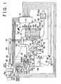
- FIG. 1 is a block diagram schematically showing a structure of a vehicular diesel engine and a control apparatus to which the invention is applied. Note that the invention can be applied to a lean-burn gasoline engine or the like having a catalyst structure similar to that in the embodiment.
- a diesel engine 2 includes a plurality of cylinders.
- the diesel engine 2 includes four cylinders, #1, #2, #3 and #4.
- a combustion chamber 4 of each of the cylinders #1, #2, #3 and #4 is coupled to a surge tank 12 via an intake port 8 opened/closed by an intake valve 6, and an intake manifold 10.
- the surge tank 12 is then coupled to an intercooler 14 and an outlet side of a compressor 16a of a supercharger, that is, an exhaust turbocharger 16 in the embodiment, through an intake passage 13.
- An inlet side of the compressor 16a is coupled to an air cleaner 18.
- An EGR gas supply port 20a of an exhaust gas re-circulation (hereinafter, referred to as "EGR") passage 20 opens into the surge tank 12.
- a throttle valve 22 is provided in the intake passage 13 connecting the surge tank 12 to the intercooler 14.
- An intake air amount sensor 24 and an intake air temperature sensor 26 are provided between the compressor 16a and the air cleaner 18.
- the combustion chamber 4 of each of the cylinders #1, #2, #3 and #4 is coupled to an inlet side of an exhaust turbine 16b of the exhaust turbocharger 16 via an exhaust port 30 opened/closed by an exhaust valve 28, and an exhaust manifold 32.
- An outlet side of the exhaust turbine 16b is connected to an exhaust passage 34.
- the exhaust turbine 16b takes in exhaust gas from the fourth cylinder #4 side in the exhaust manifold 32.
- a NOx storage reduction catalyst 36a is housed in the first catalytic converter 36 provided uppermost stream among the three catalytic converters.
- NOx is stored in the NOx storage reduction catalyst.
- exhaust gas .is in the reducing atmosphere i.e., when the air-fuel ratio is equal to or lower than the stoichiometric air-fuel ratio
- the NOx stored in the NOx storage reduction catalyst 36a is released as NO, and reduced by HC and CO. NOx is thus purified.
- a filter 38a having a wall portion formed in a monolithic structure is stored.
- the wall portion is configured such that exhaust gas flows through micropores formed in the wall portion. Since a layer of the NOx storage reduction catalyst is formed on the micropore surface of the filter 38a by coating, NOx is purified as described above.
- particulate (hereinafter, referred to as "PM") in exhaust gas is captured in the wall portion of the filter. Therefore, oxidation of PM is started by active oxygen which is generated when NOx is stored in the oxidizing atmosphere at a high temperature. Further, the entire PM is oxidized by ambient excessive oxygen. Thus, not only NOx but also PM is purified.
- the first catalytic converter 36 and the second catalytic converter 38 are integrally formed in the embodiment.
- an oxidation catalyst 40a is housed, and HC and CO are oxidized and purified therein.
- a first air-fuel ratio sensor 42 is provided upstream from the NOx storage reduction catalyst 36a.
- a first exhaust gas temperature sensor 44 is provided between the NOx storage reduction catalyst 36a and the filter 38a.
- a second exhaust gas temperature sensor 46 is provided near the filter 38a, and a second air-fuel ratio sensor 48 is provided near the oxidation catalyst 40a.
- Each of the first air-fuel ratio sensor 42 and the second air-fuel ratio sensor 48 detects an air-fuel ratio in exhaust gas at a position thereof based on components of the exhaust gas, and linearly outputs a voltage signal proportional to the air-fuel ratio.
- the first exhaust gas temperature sensor 44 and the second exhaust gas temperature sensor 46 detect an exhaust gas temperature Texin and an exhaust gas temperature Texout at a position thereof.
- a pipe of a pressure difference sensor 50 is provided on each of the upstream side and the downstream side of the filter 38a.
- the pressure difference sensor 50 detects a pressure difference between the upstream side and the downstream side of the filter 38a, in order to detect clogging in the filter 38a.
- An EGR gas inlet 20b of the EGR passage 20 opens into the exhaust manifold 32.
- the EGR gas inlet 20b opens on the first cylinder #1 side, that is opposite to the fourth cylinder #4 side on which the exhaust turbine 16b takes in exhaust gas.
- an iron EGR catalyst 52 for reforming the EGR gas is provided on the EGR gas inlet 20b side. Further, an EGR cooler 54 for cooling the EGR gas is provided downstream from the iron EGR catalyst 52 in the EGR passage 20. The EGR catalyst 52 also has a function of preventing clogging in the EGR cooler 54.
- An EGR valve 56 is provided on the EGR gas supply port 20a side. The amount of EGR gas supplied from the EGR gas supply port 20a to the intake system can be adjusted by adjusting the opening amount of EGR valve 56.
- a fuel injection valve 58 which is provided in each of the cylinders #1 to #4 and which directly injects fuel into the combustion chamber 4, is coupled to a common rail 60 via a fuel supply pipe 58a. Fuel is supplied from an electrically controlled discharge amount variable fuel pump 62 into the common rail 60, and high pressure fuel supplied from the fuel pump 62 into the common rail 60 is distributed to each fuel injection valve 58 via each fuel supply pipe 58a. A fuel pressure sensor 64 for detecting a fuel pressure is attached to the common rail 60.
- low pressure fuel is supplied to a supply valve 68 via a fuel supply pipe 66 from the fuel pump 62.
- the supply valve 68 is provided in the exhaust port 30 of the fourth cylinder #4, and supplies fuel into exhaust gas by injecting fuel to the exhaust turbine 16b side. Due to this fuel supply, a catalyst control mode, to be described later, is performed.
- An electronic control unit (hereinafter, referred to as an "ECU") 70 mainly includes a digital computer provided with a CPU, ROM, RAM and the like, and a drive circuit for driving various devices.
- the ECU 70 reads signals from the intake air amount sensor 24, the intake air temperature sensor 26, the first air-fuel ratio sensor 42, the first exhaust gas temperature sensor 44, the second exhaust gas temperature sensor 46, the second air-fuel ratio sensor 48, the pressure difference sensor 50, an EGR vale opening amount sensor in the ECG valve 56, the fuel pressure sensor 64 and a throttle valve opening amount sensor 22a.
- the ECU 70 reads signals from an accelerator pedal operation amount sensor 74 for detecting an operation amount of an accelerator pedal 72, and a coolant temperature sensor 76 for detecting a temperature of a coolant for the diesel engine 2. Further, the ECU 70 reads signals from an engine rotational speed sensor 80 for detecting a rotational speed NE of a crankshaft 78, and a cylinder identifying sensor 82 for identifying a cylinder by detecting a rotational phase of the crankshaft 78 or a rotational phase of an inlet cam.
- the ECU 70 Based on the engine operation state obtained based on these signals, the ECU 70 performs control of the fuel injection timing and fuel injection amount using the fuel injection valve 58. In addition, the ECU 70 performs control of the opening amount of EGR valve 56, control of throttle valve opening amount using a motor 22b, and control of the discharge amount from the fuel pump 62, and further, PM recovery control and sulfur poisoning recovery control, to be described later.
- EGR control is performed for adjusting a throttle valve opening amount and the EGR valve opening amount in coordination, such that an EGR rate becomes equal to a target EGR rate which is set based on an engine load and the engine rotational speed NE.
- intake air amount feedback control is performed for adjusting the EGR valve opening amount such that an intake air amount becomes equal to a target intake air amount which is set based on the engine load and the engine rotational speed NE (the target value for one rotation of the engine).
- the fuel injection amount is used as the engine load.
- the accelerator pedal operating amount may be used as the engine load.
- a combustion mode performed by the ECU 70 includes two types of combustion mode, that are, a normal combustion mode and a low temperature combustion mode.
- the ECU 70 selects the combustion mode from among these two combustion modes according to the operation state.
- the low temperature combustion mode an increase in the combustion temperature is slowed by a large amount of re-circulated exhaust, and the amounts of both NOx and smoke are simultaneously reduced.
- the low temperature combustion mode is performed mainly in a region where a low load is applied and the rotational speed is low or medium.
- the combustion mode other than the low temperature combustion mode is the normal combustion mode in which normal EGR control (including a case where exhaust gas re-circulation is not performed) is performed.
- a catalyst control mode in which a control process for the catalyst is performed, includes a PM recovery control mode, a sulfur poisoning recovery control mode, a NOx reduction control mode and a normal control mode.
- PM recovery mode PM accumulated on the filter 38a in the second catalytic converter 38 is burned by increasing the temperature, as described above, decomposed into CO2 and H2O, and released.
- the catalyst bed temperature is increased (to 600 to 700 °C, for example) by repeatedly supplying fuel from the supply valve 68 at an air-fuel ratio higher than the stoichiometric air-fuel ratio. Further, an after-fuel injection may be performed by the fuel injection valve 58.
- the sulfur poisoning recovery control mode if sulfur poisoning occurs in the NOx storage reduction catalyst 36a and the filter 38a, and the NOx storage ability thereof is reduced, the NOx storage reduction catalyst 36a and the filter 38a are made to release the sulfur component therefrom so as to be recovered from sulfur poisoning.
- the temperature increasing process is performed by repeatedly supplying fuel from the supply valve 68 and increasing the catalyst bed temperature (to 600 to 700 °C, for example).
- the air-fuel ratio decreasing process for decreasing the air-fuel ratio to a value equal to or slightly lower than the stoichiometic air-fuel ratio is performed.
- an after-fuel injection may be performed by the fuel injection valve 58.
- the NOx stored in the NOx storage reduction catalyst 36a and the filter 38a is reduced to N2, CO2 and H2O, and released.
- the process for decreasing an air-fuel ratio to a value equal to or lower than the stoichiometric air-fuel ratio is performed by making the catalyst bed temperature relatively low (250 to 500°C, for example) by intermittently supplying fuel from the supply valve 68 at relatively long time intervals.
- the mode other than these three catalyst control modes is the normal control mode.
- fuel supply from the supply valve 68 and the after-injection by the fuel injection valve 58 are not performed.
- the flowchart in FIG. 2 shows the sulfur poisoning amount Sx calculating/determining routine performed by the ECU 70.
- the sulfur poisoning amount Sx for the NOx storage reduction catalyst on the filter 38a and the NOx storage reduction catalyst 36a is calculated, and whether a sulfur poisoning recovery control process, to be described later, is to be performed is determined.
- the routine is performed as an interrupt at predetermined intervals.
- step S 100 it is initially determined in step S 100 whether sulfur release control in the sulfur poisoning recovery control is being performed.
- the "sulfur release control” signifies the control for making the catalyst release the sulfur component therefrom and recover from sulfur poisoning by performing the air-fuel ratio decreasing process after the catalyst bed temperature is increased by the temperature increasing process during the sulfur poisoning recovery control.
- the sulfur poisoning amount Sx is calculated according to an equation "1" in step S106.
- a previous value Sxold on the right-hand side is the sulfur poisoning amount Sx which is calculated in the previous control cycle.
- a sulfur poisoning increase amount Sinc shows an amount of sulfur component in the fuel to be supplied to the filter 38a and the NOx storage reduction catalyst 36a during one control cycle.
- the sulfur component amount is obtained based on a fuel injection amount Q from the fuel injection valve 58 and the engine rotational speed NE according to a map or by calculation.
- step S108 it is determined in step S108 whether the sulfur poisoning amount Sx is smaller than a reference value Smax.
- the reference value Smax signifies the maximum poisoning amount for the filter 38a and the NOx storage reduction catalyst 36a which are set to start the sulfur poisoning recovery control.
- step S112 When the sulfur poisoning amount Sx is smaller than the reference value Smax (Sx ⁇ Smax) ("YES" in step S108), it is then determined in step S112 whether the sulfur poisoning amount Sx is larger than "0" (Sx > "0"). When it is determined that the sulfur poisoning amount Sx is larger than "0" (Sx > "0") ("YES" in step S112), the routine ends.
- the sulfur poisoning recovery control is set to be performed in S110.
- the sulfur poisoning recovery control is performed.
- the temperature increasing process for increasing the temperatures of the filter 38a and the NOx storage reduction catalyst 36a is performed, and the air-fuel ratio decreasing process for making the air-fuel ratio rich (decreasing the air-fuel ratio to a value equal to or slightly lower than the stoichiometric air-fuel ratio, in the embodiment) by supplying fuel from the supply valve 68 is performed.
- the sulfur poisoning amount Sx is computed according to the equation "1", as described above. Therefore, the sulfur poisoning amount Sx has not started to decrease.
- the sulfur release control by the air-fuel ratio decreasing process is started, and the air-fuel ratio in exhaust gas is adjusted to the target air-fuel ratio (an air-fuel ratio slightly lower than the stoichiometric air-fuel ratio, in the embodiment) by supplying fuel from the supply valve 68.
- the sulfur release control is thus started (“YES” in step S100)
- the sulfur release determination flag Fsr is a flag which is set by a sulfur release determination flag Fsr setting routine shown in FIG. 3 , and shows whether the sulfur component can be actually released from the filter 38a and the NOx storage reduction catalyst 36a.
- the air-fuel ratio decreasing process is performed so as to decrease the air-fuel ratio to a target air-fuel ratio, which is slightly lower than the stoichiometric air-fuel ratio (the air-fuel ratio ⁇ "14.3", in the embodiment).
- step S206 it is then determined in step S206 whether an upstream side exhaust gas temperature Texin, which is detected by the first exhaust gas temperature sensor 44 provided between the NOx storage reduction catalyst 36a and the filter 38a, is higher than a high temperature determination reference temperature Tsin.
- the upstream side exhaust gas temperature Texin accurately reflects the catalyst bed temperature of the NOx storage reduction catalyst 36a.
- the high temperature determination reference temperature Tsin is a reference temperature which shows the fact that the catalyst bed temperature of the NOx storage reduction catalyst 36a is increased to a value at which the sulfur component can be released.
- the high temperature determination reference temperature Tsin is the reference temperature which also shows the fact that the catalyst bed temperature of the filter 38a on the downstream side has already reached the temperature at which the sulfur component can be released or will be immediately increased to the catalyst bed temperature at which the sulfur component can be released.
- step S208 When it is determined that the upstream side exhaust gas temperature Texin is equal to or lower than the high temperature determination reference temperature Tsin (Texin ⁇ Tsin) ("NO" in S206), it is then determined in step S208 whether a downstream side exhaust gas temperature Texout, which is detected by the second exhaust gas temperature sensor 46 provided downstream from the filter 38a, is higher than a high temperature determination reference temperature Tsout.
- the downstream side exhaust gas temperature Texout accurately reflects the catalyst bed temperature of the filter 38a.
- the high temperature determination reference temperature Tsout is the reference temperature which also shows the fact that the catalyst bed temperature of the filter 38 has increased to a temperature at which the sulfur component can be released.
- the sulfur release determination flag Fsr is set to "OFF” in step S212.
- the routine then ends. Therefore, even when the air-fuel ratio AF is equal to or lower than the reference air-fuel ratio AFr (AF ⁇ AFr), the sulfur release determination flag Fsr is kept “OFF” while the upstream side exhaust gas temperature Texin is equal to or lower than the high temperature determination reference temperature (Texin ⁇ Tsin) and the downstream side exhaust gas temperature is equal to or lower than the high temperature determination reference temperature (Texout ⁇ Tsout).
- the upstream side exhaust gas temperature Texin is equal to or lower than the high temperature determination reference temperature Tsin (Texin ⁇ Tsin) ("NO” in step S206), and the downstream side exhaust gas temperature Texout is higher than the high temperature determination reference temperature (Texout > Tsout) ("YES" in step S208), the sulfur release determination flag Fsr is set to "ON" in step S210.
- the sulfur release determination flag is set to "ON".
- a sulfur release amount Sdec shows an amount of the sulfur component released from the filter 38a and the NOx storage reduction catalyst 36a during one control cycle.
- the sulfur release amount Sdec is set to a predetermined value. Since the sulfur poisoning increase amount Sinc is considerably smaller than the sulfur release amount Sdec (Sinc ⁇ Sdec), the sulfur poisoning amount Sx decreases by the computation according to the equation "2". Namely, the sulfur poisoning recovery computation is performed.
- step S102 when an affirmative determination is made in step S102, the sulfur poisoning amount Sx is repeatedly decreased.
- step S 114 When the sulfur poisoning amount Sx becomes equal to or smaller than "0" (Sx ⁇ "0") ("NO” in step S112) due to a decrease in the sulfur poisoning amount Sx, it is then determined in step S 114 whether the sulfur poisoning recovery control is being performed. In this case, since the sulfur poisoning recovery control is being performed ("YES" in step S 114), the sulfur poisoning recovery control is set to be stopped, in step S 116. The sulfur poisoning recovery control is thus stopped.
- step S118 the value of the sulfur poisoning amount Sx is reset to "0" in step S118, afterwhich the routine ends.
- the sulfur release control is not performed since the sulfur poisoning recovery control is stopped ("NO" in step S100). Accordingly, the sulfur poisoning amount Sx increasing computation according to the equation "1" is started, and the process returns to the initial state.
- FIG. 4 shows a temperature distribution in the exhaust system when the sulfur release control is performed in the state where no failure has occurred in the NOx storage reduction catalyst 36a.
- the upstream side exhaust gas temperature Texin detected at a position p2 of the first exhaust gas temperature sensor 44 is approximate to a catalyst bed temperature Ta of the NOx storage reduction catalyst 36a (shown by "CatA") and a catalyst bed temperature Tb of the filter 38a (shown by "CatB”), and actually has a high correlation with the catalyst bed temperatures Ta and Tb.
- the downstream side exhaust gas temperature Texout detected at a position p5 of the second exhaust gas temperature sensor 46 is approximate to the catalyst bed temperature Tb of the filter 38a (CatB), and actually has a high correlation with the catalyst bed temperature Tb.
- the upstream side exhaust gas temperature Texin is higher than the high temperature determination reference temperature (Texin > Tsin)
- the downstream side exhaust gas temperature Texout is higher than the high temperature determination reference temperature Tsout (Texout > Tsout)
- it can be determined that at least the catalyst bed temperature of the filter 38a has reached the value at which the sulfur component can be released.
- FIG. 5 shows a temperature distribution in the exhaust system when the sulfur release control is being performed in the state where a failure has occurred in the NOx storage reduction catalyst 36a due to degradation thereof.
- the upstream side exhaust gas temperature Texin detected at the position p2 of the first exhaust gas temperature sensor 44 is approximate to the catalyst bed temperature Ta of the NOx storage reduction catalyst 36a (CatA), and has a high correlation with the catalyst bed temperatures Ta.
- the upstream side exhaust gas temperature Texin is not approximate to the catalyst bed temperature Tb of the filter 38a (CatB), and has a low correlation with the catalyst bed temperature Tb.
- the downstream side exhaust gas temperature Texout detected at the position p5 of the second exhaust gas temperature sensor 46 is approximate to the catalyst bed temperature Tb of the filter 38a (CatB) and has a high correlation with the catalyst bed temperature Tb.
- At least the degree of the catalyst bed temperature Tb of the filter 38a (CatB) at the present time or immediately after the present time can be determined based on the upstream side exhaust gas temperature Texin, or the downstream side exhaust gas temperature Texout. Therefore, when the downstream side exhaust gas temperature Teout is higher than the high temperature determination reference temperature Tsout (Texout > Tsout), the equation "2" is applied, and the sulfur poisoning recovery computation is performed.
- the downstream side exhaust gas temperature Texout is approximate to the catalyst bed temperature Tb of the filter 38a (CatB) and has a high correlation with the catalyst bed temperature Tb. Therefore, the degree of the catalyst bed temperature Tb of the filter 38a (Cat B) is estimated as shown by the solid line, and the equation "2" is applied on the assumption that the sulfur component is released. Therefore, the sulfur poisoning recovery computation is performed.
- the second air-fuel ratio sensor 48 corresponds to air-fuel ratio detecting means.
- Steps S102, S104 and S106 of the sulfur poisoning amount Sx calculating/determining routine ( FIG. 2 ) performed by the ECU 70 and the sulfur release determination flag Fsr setting routine ( FIG. 3 ) correspond to the process as sulfur poisoning recovery computing means.
- the upstream side exhaust gas temperature Texin detected by the first exhaust gas temperature sensor 44 shows a temperature which accurately reflects the catalyst bed temperature of the NOx storage reduction catalyst 36a on the upstream side from among the two exhaust has control catalysts (the NOx storage reduction catalyst 36a and the filter 38a). Accordingly, when the upstream side exhaust gas temperature Texin is higher than the high temperature determination reference temperature Tsin, it can be determined that the catalyst bed temperature of the NOx storage reduction catalyst 36a on the upstream side has reached the value at which the sulfur component can be released. Based on this, it can be determined that the catalyst bed temperature of the filter 38a on the downstream side has already reached the value at which the sulfur component can be released or will be immediately increased to the value at which the sulfur component can be released.
- the downstream side exhaust gas temperature Texout detected by the second exhaust gas temperature sensor 46 accurately reflects a catalyst bed temperature of the filter 38a on the downstream side from among the two exhaust gas control catalysts. Accordingly, when the downstream side exhaust gas temperature Texout is higher than the high temperature determination reference temperature Tsout, it can be determined that at least the catalyst bed temperature of the filter 38a on the downstream side has reached the value at which the sulfur component can be released.
- the sulfur poisoning recovery computation is performed.
- the degree of recovery from sulfur poisoning that is, the sulfur poisoning amount Sx obtained according to the equation "2"
- the temperature increasing process for the catalyst bed temperature of the filter 38a and the air-fuel ratio decreasing process can be appropriately performed by the sulfur poisoning recovery control. Accordingly, even when a failure, e.g., degradation and clogging, has occurred in the NOx storage reduction catalyst 36a on the upstream side, heat degradation of the filter 38a on the downstream side is not promoted, and reduction in fuel efficiency is not caused.
- the sulfur release determination flag Fsr setting routine ( FIG. 6 ) will be described.
- the routine is repeatedly performed at predetermined intervals.
- it is initially determined in step S302 whether the sulfur release control is being performed.
- the sulfur release determination flag Fsr is set to "OFF” in step S320.
- step S 304 it is then determined in step S 304 whether the air-fuel ratio AF detected by the second air-fuel ratio 48 is equal to or lower than the reference air-fuel ratio AFr at which the sulfur component can be released.
- the reference air-fuel ratio AFr is as explained in the description of step S204 in FIG. 3 .
- the air-fuel ratio decreasing process in the sulfur release control is as explained in the description of step S204 in FIG. 3 .
- step S306 When the air-fuel ratio AF becomes equal to or lower than the reference air-fuel ratio AFr (AF ⁇ AFr) ("YES" in step S304), it is then determined in step S306 whether the NOx storage reduction catalyst 36a on the upstream side is determined not to have a failure. The determination as to whether a failure has occurred in the NOx storage reduction catalyst 36a will be described later.
- step S308 When the NOx storage reduction catalyst 36a is determined not to have a failure ("YES" in step S306), it is then determined in step S308 whether the upstream side exhaust gas temperature Texin detected by the first exhaust gas temperature sensor 44 is higher than the high temperature determination reference temperature Tsin.
- the upstream side exhaust gas temperature Texin and the high temperature determination reference temperature Tsin are as explained in the description of step S206 in FIG. 3 .
- step S308 when it is determined that the upstream side exhaust gas temperature Texin is equal to or lower than the high temperature determination reference temperature Tsin (Texin ⁇ Tsin) ("NO" in step S308), the time in which the upstream side exhaust gas temperature Texin is kept equal to or lower than the high temperature determination reference temperature Tsin (Texin ⁇ Tsin) is measured in step S 310. The continuation time is measured in order to determine whether a failure has occurred in the NOx storage reduction catalyst 36a.
- the upstream side exhaust gas temperature Texin is kept equal to or lower than the high temperature determination reference temperature Tsin (Texin ⁇ Tsin) even when the sulfur release control is being performed after the temperature increasing process is performed in the sulfur poisoning recovery control, it can be determined that a failure has occurred in the NOx storage reduction catalyst 36a.
- step S312 it is determined in step S312 whether the continuation time has exceeded a failure determination reference time.
- the sulfur release determination flag Fsr is kept “OFF” in step S320. The routine then ends.
- step S310 the continuation time is repeatedly measured in step S310 and the continuation time becomes longer than the failure determination reference time ("YES" in step S312), it is determined in step S314 that a failure has occurred in the catalyst on the upstream side. Namely, it is determined that a failure has occurred in the NOx storage reduction catalyst 36a, and the NOx storage reduction catalyst 36a hardly serves as a catalyst.
- step S316 it is determined in step S316 whether the downstream side exhaust gas temperature Texout detected by the second exhaust gas temperature sensor 46 is higher than the high temperature determination reference temperature Tsout.
- the downstream side exhaust gas temperature Texout and the high temperature determination reference temperature Tsout are as explained in the description of step S208 in FIG. 3 .
- step S316 When it is determined that the downstream side exhaust gas temperature Texout is equal to or lower than the high temperature determination reference temperature Tsout (Texout ⁇ Tsout) ("NO" in step S316), the sulfur release determination flag Fsr is set to "OFF" in step S320. The routine then ends. In the next control routine, since it has been determined that a failure has occurred in the NOx storage reduction catalyst 36 ("NO" in step S306), it is immediately determined in step S316 whether the downstream side exhaust gas temperature Texout is higher than the high temperature determination reference temperature Tsout.
- the sulfur release determination flag Fsr is set to "ON".
- the sulfur poisoning amount Sx calculating/determining routine ( FIG. 2 ) is performed as described above, based on whether the sulfur release determination flag Fsr is "ON" or "OFF".
- the second air-fuel ratio sensor 48 corresponds to air-fuel ratio detecting means.
- Steps S102, S104 and S106 in the sulfur poisoning amount Sx calculating/determining routine ( FIG. 2 ) performed by the ECU 70 and the sulfur release determination flag Fsr setting routine ( FIG. 6 ) correspond to the process as sulfur poisoning recovery computing means.
- the sulfur poisoning recovery computation is performed, when the upstream side exhaust gas temperature Texin is higher than the high temperature determination reference temperature Tsin in the state where the air-fuel ratio is decreased to a value equal to or lower than the reference air-fuel ratio AFr.
- the degree of recovery from sulfur poisoning can be obtained with high accuracy.
- the sulfur poisoning amount Sx according to the equation "2" can be obtained with high accuracy.
- the sulfur poisoning recovery computation is performed when the downstream side exhaust gas temperature Texout is higher than the high temperature determination reference temperature Tsout in the state where the air-fuel ratio is decreased to a value equal to or lower than the reference air-fuel ratio AFr.
- the degree of recovery from sulfur poisoning can be obtained with high accuracy.
- the sulfur poisoning amount Sx according to the equation "2" can be obtained with high accuracy.
- the temperature increasing process for the catalyst bed temperature of the filter 38a and the air-fuel ratio decreasing process can be appropriately performed by the sulfur poisoning recovery control.
- heat degradation of the filter 38a on the downstream side is not promoted and reduction in fuel efficiency is not caused, even when a failure, e.g., degradation and clogging, occurs in the NOx storage reduction catalyst 36a on the upstream side.
- a structure including two exhaust gas control catalysts (the NOx storage reduction catalyst 36a and the filter 38a) which are subject to sulfur poisoning.
- a structure may include three or more exhaust gas control catalysts which are subject to sulfur poisoning. The above-mentioned effects can be obtained by performing the control in the above-mentioned embodiments based on the exhaust gas temperatures on the upstream side and the downstream side of at least one of the second exhaust gas control catalyst and subsequent catalysts in a direction from the upstream side to the downstream side.
- each of the second exhaust gas control catalyst and subsequent catalysts in a direction from the upstream side to the downstream side has a structure in which a filter for filtering PM in exhaust gas is used as the base and the layer of the NOx storage reduction catalyst is formed on the filter.
- a catalyst having the same structure as that of the NOx storage reduction catalyst 36a on the upstream side may be used.
- the upstream side exhaust gas temperature Texin which is detected by the first exhaust gas temperature sensor 44 provided upstream from the filter 38a
- the downstream side exhaust gas temperature Texout which is detected by the second exhaust gas temperature sensor 46 provided downstream from the filter 38a
- the upstream side exhaust gas temperature Texin is subject to determination.
- the downstream side exhaust gas temperature Texout is subject to determination.
- the sulfur release determination flag Fsr may be set by determining whether the downstream side exhaust gas temperature Texout is higher/lower than the high temperature determination reference temperature Tsout regardless of whether a failure has occurred in the NOx storage reduction catalyst 36a. Namely, when the downstream side exhaust gas temperature Texout is higher than the high temperature determination reference temperature Tsout (Texout > Tsout) during the air-fuel ratio decreasing process, the sulfur release determination flag Fsr is set to "ON". On the other hand, when the downstream side exhaust gas temperature Texout is equal to or lower than the high temperature determination reference temperature Tsout (Texout ⁇ Tsout) during the air-fuel ratio decreasing process, the sulfur release determination flag Fsr is set to "OFF".
- the continuation time is measured (step S310) during the sulfur release control.
- the failure determination may be performed by starting measurement of the continuation time from the temperature increasing process performed at the beginning of the sulfur poisoning recovery control. Also, instead of performing steps S310 and S312, it may be determined in step S314 that a failure has occurred in the NOx storage reduction catalyst 36a, immediately after a negative determination is made in step S308.
Landscapes
- Engineering & Computer Science (AREA)
- Chemical & Material Sciences (AREA)
- Combustion & Propulsion (AREA)
- Mechanical Engineering (AREA)
- General Engineering & Computer Science (AREA)
- Chemical Kinetics & Catalysis (AREA)
- Exhaust Gas After Treatment (AREA)
- Exhaust Gas Treatment By Means Of Catalyst (AREA)
Applications Claiming Priority (2)
| Application Number | Priority Date | Filing Date | Title |
|---|---|---|---|
| JP2003318109 | 2003-09-10 | ||
| JP2003318109A JP4239765B2 (ja) | 2003-09-10 | 2003-09-10 | 内燃機関の排気浄化触媒制御方法及び排気浄化触媒制御装置 |
Publications (3)
| Publication Number | Publication Date |
|---|---|
| EP1515030A2 EP1515030A2 (en) | 2005-03-16 |
| EP1515030A3 EP1515030A3 (en) | 2005-07-13 |
| EP1515030B1 true EP1515030B1 (en) | 2011-03-16 |
Family
ID=34131995
Family Applications (1)
| Application Number | Title | Priority Date | Filing Date |
|---|---|---|---|
| EP04021488A Expired - Lifetime EP1515030B1 (en) | 2003-09-10 | 2004-09-09 | Method and apparatus for controlling sulfur poisoning recovery of a catalyst |
Country Status (4)
| Country | Link |
|---|---|
| EP (1) | EP1515030B1 (ja) |
| JP (1) | JP4239765B2 (ja) |
| DE (1) | DE602004031811D1 (ja) |
| ES (1) | ES2363222T3 (ja) |
Families Citing this family (10)
| Publication number | Priority date | Publication date | Assignee | Title |
|---|---|---|---|---|
| JP4506546B2 (ja) * | 2005-04-21 | 2010-07-21 | トヨタ自動車株式会社 | 内燃機関の排気浄化システム |
| JP4241784B2 (ja) | 2006-08-30 | 2009-03-18 | トヨタ自動車株式会社 | 内燃機関の排気浄化システム |
| FR2906839B1 (fr) * | 2006-10-05 | 2008-12-05 | Renault Sas | Systeme et procede d'estimation de la quantite de particules piegees par un filtre a particules |
| FR2910930B1 (fr) * | 2006-12-27 | 2009-02-06 | Renault Sas | Systeme d'injection de carburant d'un moteur a combustion interne pour compenser les perturbations lors de la regeneration du filtre a particules et procede de commande associe |
| JP4803107B2 (ja) | 2007-05-15 | 2011-10-26 | トヨタ自動車株式会社 | 内燃機関の排気浄化装置 |
| FR2927372A1 (fr) * | 2008-02-12 | 2009-08-14 | Renault Sas | Procede de commande d'alimentation en carburant d'une ligne d'echappement d'un moteur a combustion et dispositif mettant en oeuvre le procede |
| WO2012025976A1 (ja) * | 2010-08-23 | 2012-03-01 | トヨタ自動車株式会社 | 内燃機関の排気浄化装置 |
| GB2529781A (en) * | 2015-12-01 | 2016-03-02 | Gm Global Tech Operations Inc | Method of detecting a clogging of a fuel injector in an internal combustion engine |
| US9925974B2 (en) * | 2016-04-26 | 2018-03-27 | Ford Global Technologies, Llc | System and methods for improving fuel economy |
| CN112539114B (zh) * | 2020-12-01 | 2022-11-29 | 潍柴动力股份有限公司 | 催化剂硫中毒的处理方法及装置、电子设备、存储介质 |
Family Cites Families (7)
| Publication number | Priority date | Publication date | Assignee | Title |
|---|---|---|---|---|
| DE4100397C2 (de) * | 1990-02-10 | 1999-08-05 | Volkswagen Ag | Verfahren und Anordnung zur Überwachung des Konvertierungsgrads eines Katalysators |
| EP0892158B1 (de) * | 1997-07-19 | 2003-02-12 | Volkswagen Aktiengesellschaft | Verfahren und Vorrichtung zur Überwachung der De-Sulfatierung bei NOx-Speicherkatalysatoren |
| DE19731623B4 (de) * | 1997-07-23 | 2006-11-23 | Volkswagen Ag | Verfahren und Vorrichtung zur De-Sulfatierung von NOx-Speichern bei Dieselmotoren |
| DE19959605A1 (de) * | 1999-12-10 | 2001-06-13 | Volkswagen Ag | Vorrichtung und Verfahren zur NOx- und/oder SOx-Regeneration eines NOx-Speicherkatalysators |
| JP4631123B2 (ja) * | 2000-03-16 | 2011-02-16 | マツダ株式会社 | エンジンの排気浄化装置 |
| JP3514218B2 (ja) * | 2000-07-24 | 2004-03-31 | トヨタ自動車株式会社 | 内燃機関の排気浄化装置 |
| JP3685033B2 (ja) * | 2000-10-17 | 2005-08-17 | トヨタ自動車株式会社 | 内燃機関の排気浄化装置 |
-
2003
- 2003-09-10 JP JP2003318109A patent/JP4239765B2/ja not_active Expired - Fee Related
-
2004
- 2004-09-09 ES ES04021488T patent/ES2363222T3/es not_active Expired - Lifetime
- 2004-09-09 DE DE602004031811T patent/DE602004031811D1/de not_active Expired - Lifetime
- 2004-09-09 EP EP04021488A patent/EP1515030B1/en not_active Expired - Lifetime
Also Published As
| Publication number | Publication date |
|---|---|
| EP1515030A3 (en) | 2005-07-13 |
| JP4239765B2 (ja) | 2009-03-18 |
| EP1515030A2 (en) | 2005-03-16 |
| ES2363222T3 (es) | 2011-07-27 |
| JP2005083298A (ja) | 2005-03-31 |
| DE602004031811D1 (de) | 2011-04-28 |
Similar Documents
| Publication | Publication Date | Title |
|---|---|---|
| US7299625B2 (en) | Exhaust purifying apparatus and exhaust purifying method for internal combustion engine | |
| EP1778954B1 (en) | Exhaust purifying apparatus and exhaust purifying method for internal combustion engine | |
| EP1723323B1 (en) | Exhaust purifying apparatus for internal combustion engine | |
| US7677029B2 (en) | Regeneration controller for exhaust purification apparatus of internal combustion engine | |
| US7836685B2 (en) | Regeneration controller for exhaust purification apparatus of internal combustion engine | |
| WO2007136141A1 (ja) | 内燃機関の排気浄化装置 | |
| EP1866526B1 (en) | Exhaust gas purifier for internal combustion engine | |
| US7841169B2 (en) | Regeneration controller for exhaust purification apparatus of internal combustion engine | |
| EP1515030B1 (en) | Method and apparatus for controlling sulfur poisoning recovery of a catalyst | |
| EP1515017B1 (en) | Catalyst control apparatus of internal combustion engine | |
| EP1326010A2 (en) | Exhaust gas purification apparatus and process for internal combustion engine | |
| EP1505271A1 (en) | Reducing agent supply error detecting method for an exhaust gas control catalyst and corresponding detecting apparatus | |
| WO2007138454A1 (en) | Exhaust purification device and method of internal combustion engine | |
| EP1536120B1 (en) | Exhaust gas control apparatus for internal combustion engine and control method thereof | |
| EP1519021B1 (en) | Catalyst deterioration determination apparatus of internal combustion engine | |
| EP1536121B1 (en) | Catalyst control apparatus for internal combustion engine and method for performing catalyst control | |
| EP1711697B1 (en) | Exhaust gas control system for internal combustion engine and method for recovering filter thereof | |
| EP1510679B1 (en) | Excessive sulfur poisoning recovery control method and apparatus for exhaust gas control catalyst | |
| EP0953742B1 (en) | Compression-ignition internal combustion engine having combustion heater | |
| CN110945218B (zh) | 排气净化系统 | |
| JP4148072B2 (ja) | 内燃機関の触媒制御方法及び触媒制御装置 | |
| JP2000170527A (ja) | 内燃機関の排気浄化装置 |
Legal Events
| Date | Code | Title | Description |
|---|---|---|---|
| PUAI | Public reference made under article 153(3) epc to a published international application that has entered the european phase |
Free format text: ORIGINAL CODE: 0009012 |
|
| 17P | Request for examination filed |
Effective date: 20040909 |
|
| AK | Designated contracting states |
Kind code of ref document: A2 Designated state(s): AT BE BG CH CY CZ DE DK EE ES FI FR GB GR HU IE IT LI LU MC NL PL PT RO SE SI SK TR |
|
| AX | Request for extension of the european patent |
Extension state: AL HR LT LV MK |
|
| PUAL | Search report despatched |
Free format text: ORIGINAL CODE: 0009013 |
|
| AK | Designated contracting states |
Kind code of ref document: A3 Designated state(s): AT BE BG CH CY CZ DE DK EE ES FI FR GB GR HU IE IT LI LU MC NL PL PT RO SE SI SK TR |
|
| AX | Request for extension of the european patent |
Extension state: AL HR LT LV MK |
|
| AKX | Designation fees paid |
Designated state(s): DE ES FR GB IT |
|
| GRAP | Despatch of communication of intention to grant a patent |
Free format text: ORIGINAL CODE: EPIDOSNIGR1 |
|
| GRAS | Grant fee paid |
Free format text: ORIGINAL CODE: EPIDOSNIGR3 |
|
| GRAA | (expected) grant |
Free format text: ORIGINAL CODE: 0009210 |
|
| AK | Designated contracting states |
Kind code of ref document: B1 Designated state(s): DE ES FR GB IT |
|
| REG | Reference to a national code |
Ref country code: GB Ref legal event code: FG4D |
|
| REF | Corresponds to: |
Ref document number: 602004031811 Country of ref document: DE Date of ref document: 20110428 Kind code of ref document: P |
|
| REG | Reference to a national code |
Ref country code: DE Ref legal event code: R096 Ref document number: 602004031811 Country of ref document: DE Effective date: 20110428 |
|
| REG | Reference to a national code |
Ref country code: ES Ref legal event code: FG2A Ref document number: 2363222 Country of ref document: ES Kind code of ref document: T3 Effective date: 20110727 |
|
| PLBE | No opposition filed within time limit |
Free format text: ORIGINAL CODE: 0009261 |
|
| STAA | Information on the status of an ep patent application or granted ep patent |
Free format text: STATUS: NO OPPOSITION FILED WITHIN TIME LIMIT |
|
| 26N | No opposition filed |
Effective date: 20111219 |
|
| REG | Reference to a national code |
Ref country code: DE Ref legal event code: R097 Ref document number: 602004031811 Country of ref document: DE Effective date: 20111219 |
|
| REG | Reference to a national code |
Ref country code: GB Ref legal event code: 746 Effective date: 20130624 |
|
| REG | Reference to a national code |
Ref country code: DE Ref legal event code: R084 Ref document number: 602004031811 Country of ref document: DE Effective date: 20130614 |
|
| REG | Reference to a national code |
Ref country code: FR Ref legal event code: PLFP Year of fee payment: 12 |
|
| PGFP | Annual fee paid to national office [announced via postgrant information from national office to epo] |
Ref country code: GB Payment date: 20150909 Year of fee payment: 12 Ref country code: ES Payment date: 20150810 Year of fee payment: 12 Ref country code: DE Payment date: 20150902 Year of fee payment: 12 |
|
| PGFP | Annual fee paid to national office [announced via postgrant information from national office to epo] |
Ref country code: FR Payment date: 20150629 Year of fee payment: 12 |
|
| PGFP | Annual fee paid to national office [announced via postgrant information from national office to epo] |
Ref country code: IT Payment date: 20150925 Year of fee payment: 12 |
|
| REG | Reference to a national code |
Ref country code: DE Ref legal event code: R119 Ref document number: 602004031811 Country of ref document: DE |
|
| GBPC | Gb: european patent ceased through non-payment of renewal fee |
Effective date: 20160909 |
|
| REG | Reference to a national code |
Ref country code: FR Ref legal event code: ST Effective date: 20170531 |
|
| PG25 | Lapsed in a contracting state [announced via postgrant information from national office to epo] |
Ref country code: DE Free format text: LAPSE BECAUSE OF NON-PAYMENT OF DUE FEES Effective date: 20170401 Ref country code: FR Free format text: LAPSE BECAUSE OF NON-PAYMENT OF DUE FEES Effective date: 20160930 Ref country code: GB Free format text: LAPSE BECAUSE OF NON-PAYMENT OF DUE FEES Effective date: 20160909 |
|
| PG25 | Lapsed in a contracting state [announced via postgrant information from national office to epo] |
Ref country code: IT Free format text: LAPSE BECAUSE OF NON-PAYMENT OF DUE FEES Effective date: 20160909 |
|
| PG25 | Lapsed in a contracting state [announced via postgrant information from national office to epo] |
Ref country code: ES Free format text: LAPSE BECAUSE OF NON-PAYMENT OF DUE FEES Effective date: 20160910 |
|
| REG | Reference to a national code |
Ref country code: ES Ref legal event code: FD2A Effective date: 20181128 |