EP1536121B1 - Catalyst control apparatus for internal combustion engine and method for performing catalyst control - Google Patents
Catalyst control apparatus for internal combustion engine and method for performing catalyst control Download PDFInfo
- Publication number
- EP1536121B1 EP1536121B1 EP20040027791 EP04027791A EP1536121B1 EP 1536121 B1 EP1536121 B1 EP 1536121B1 EP 20040027791 EP20040027791 EP 20040027791 EP 04027791 A EP04027791 A EP 04027791A EP 1536121 B1 EP1536121 B1 EP 1536121B1
- Authority
- EP
- European Patent Office
- Prior art keywords
- fuel ratio
- air
- catalyst
- detected
- value
- Prior art date
- Legal status (The legal status is an assumption and is not a legal conclusion. Google has not performed a legal analysis and makes no representation as to the accuracy of the status listed.)
- Expired - Fee Related
Links
Images


Classifications
-
- F—MECHANICAL ENGINEERING; LIGHTING; HEATING; WEAPONS; BLASTING
- F02—COMBUSTION ENGINES; HOT-GAS OR COMBUSTION-PRODUCT ENGINE PLANTS
- F02D—CONTROLLING COMBUSTION ENGINES
- F02D41/00—Electrical control of supply of combustible mixture or its constituents
- F02D41/24—Electrical control of supply of combustible mixture or its constituents characterised by the use of digital means
- F02D41/2406—Electrical control of supply of combustible mixture or its constituents characterised by the use of digital means using essentially read only memories
- F02D41/2425—Particular ways of programming the data
- F02D41/2429—Methods of calibrating or learning
- F02D41/2451—Methods of calibrating or learning characterised by what is learned or calibrated
- F02D41/2454—Learning of the air-fuel ratio control
-
- F—MECHANICAL ENGINEERING; LIGHTING; HEATING; WEAPONS; BLASTING
- F01—MACHINES OR ENGINES IN GENERAL; ENGINE PLANTS IN GENERAL; STEAM ENGINES
- F01N—GAS-FLOW SILENCERS OR EXHAUST APPARATUS FOR MACHINES OR ENGINES IN GENERAL; GAS-FLOW SILENCERS OR EXHAUST APPARATUS FOR INTERNAL COMBUSTION ENGINES
- F01N3/00—Exhaust or silencing apparatus having means for purifying, rendering innocuous, or otherwise treating exhaust
- F01N3/08—Exhaust or silencing apparatus having means for purifying, rendering innocuous, or otherwise treating exhaust for rendering innocuous
- F01N3/0807—Exhaust or silencing apparatus having means for purifying, rendering innocuous, or otherwise treating exhaust for rendering innocuous by using absorbents or adsorbents
- F01N3/0828—Exhaust or silencing apparatus having means for purifying, rendering innocuous, or otherwise treating exhaust for rendering innocuous by using absorbents or adsorbents characterised by the absorbed or adsorbed substances
- F01N3/0842—Nitrogen oxides
-
- F—MECHANICAL ENGINEERING; LIGHTING; HEATING; WEAPONS; BLASTING
- F02—COMBUSTION ENGINES; HOT-GAS OR COMBUSTION-PRODUCT ENGINE PLANTS
- F02D—CONTROLLING COMBUSTION ENGINES
- F02D41/00—Electrical control of supply of combustible mixture or its constituents
- F02D41/02—Circuit arrangements for generating control signals
- F02D41/021—Introducing corrections for particular conditions exterior to the engine
- F02D41/0235—Introducing corrections for particular conditions exterior to the engine in relation with the state of the exhaust gas treating apparatus
-
- F—MECHANICAL ENGINEERING; LIGHTING; HEATING; WEAPONS; BLASTING
- F01—MACHINES OR ENGINES IN GENERAL; ENGINE PLANTS IN GENERAL; STEAM ENGINES
- F01N—GAS-FLOW SILENCERS OR EXHAUST APPARATUS FOR MACHINES OR ENGINES IN GENERAL; GAS-FLOW SILENCERS OR EXHAUST APPARATUS FOR INTERNAL COMBUSTION ENGINES
- F01N3/00—Exhaust or silencing apparatus having means for purifying, rendering innocuous, or otherwise treating exhaust
- F01N3/08—Exhaust or silencing apparatus having means for purifying, rendering innocuous, or otherwise treating exhaust for rendering innocuous
- F01N3/0807—Exhaust or silencing apparatus having means for purifying, rendering innocuous, or otherwise treating exhaust for rendering innocuous by using absorbents or adsorbents
- F01N3/0821—Exhaust or silencing apparatus having means for purifying, rendering innocuous, or otherwise treating exhaust for rendering innocuous by using absorbents or adsorbents combined with particulate filters
-
- F—MECHANICAL ENGINEERING; LIGHTING; HEATING; WEAPONS; BLASTING
- F01—MACHINES OR ENGINES IN GENERAL; ENGINE PLANTS IN GENERAL; STEAM ENGINES
- F01N—GAS-FLOW SILENCERS OR EXHAUST APPARATUS FOR MACHINES OR ENGINES IN GENERAL; GAS-FLOW SILENCERS OR EXHAUST APPARATUS FOR INTERNAL COMBUSTION ENGINES
- F01N3/00—Exhaust or silencing apparatus having means for purifying, rendering innocuous, or otherwise treating exhaust
- F01N3/08—Exhaust or silencing apparatus having means for purifying, rendering innocuous, or otherwise treating exhaust for rendering innocuous
- F01N3/0807—Exhaust or silencing apparatus having means for purifying, rendering innocuous, or otherwise treating exhaust for rendering innocuous by using absorbents or adsorbents
- F01N3/0871—Regulation of absorbents or adsorbents, e.g. purging
- F01N3/0885—Regeneration of deteriorated absorbents or adsorbents, e.g. desulfurization of NOx traps
-
- F—MECHANICAL ENGINEERING; LIGHTING; HEATING; WEAPONS; BLASTING
- F02—COMBUSTION ENGINES; HOT-GAS OR COMBUSTION-PRODUCT ENGINE PLANTS
- F02D—CONTROLLING COMBUSTION ENGINES
- F02D2200/00—Input parameters for engine control
- F02D2200/02—Input parameters for engine control the parameters being related to the engine
- F02D2200/08—Exhaust gas treatment apparatus parameters
- F02D2200/0802—Temperature of the exhaust gas treatment apparatus
-
- F—MECHANICAL ENGINEERING; LIGHTING; HEATING; WEAPONS; BLASTING
- F02—COMBUSTION ENGINES; HOT-GAS OR COMBUSTION-PRODUCT ENGINE PLANTS
- F02D—CONTROLLING COMBUSTION ENGINES
- F02D41/00—Electrical control of supply of combustible mixture or its constituents
- F02D41/02—Circuit arrangements for generating control signals
- F02D41/021—Introducing corrections for particular conditions exterior to the engine
- F02D41/0235—Introducing corrections for particular conditions exterior to the engine in relation with the state of the exhaust gas treating apparatus
- F02D41/027—Introducing corrections for particular conditions exterior to the engine in relation with the state of the exhaust gas treating apparatus to purge or regenerate the exhaust gas treating apparatus
- F02D41/0275—Introducing corrections for particular conditions exterior to the engine in relation with the state of the exhaust gas treating apparatus to purge or regenerate the exhaust gas treating apparatus the exhaust gas treating apparatus being a NOx trap or adsorbent
-
- F—MECHANICAL ENGINEERING; LIGHTING; HEATING; WEAPONS; BLASTING
- F02—COMBUSTION ENGINES; HOT-GAS OR COMBUSTION-PRODUCT ENGINE PLANTS
- F02D—CONTROLLING COMBUSTION ENGINES
- F02D41/00—Electrical control of supply of combustible mixture or its constituents
- F02D41/02—Circuit arrangements for generating control signals
- F02D41/14—Introducing closed-loop corrections
- F02D41/1438—Introducing closed-loop corrections using means for determining characteristics of the combustion gases; Sensors therefor
- F02D41/1444—Introducing closed-loop corrections using means for determining characteristics of the combustion gases; Sensors therefor characterised by the characteristics of the combustion gases
- F02D41/1454—Introducing closed-loop corrections using means for determining characteristics of the combustion gases; Sensors therefor characterised by the characteristics of the combustion gases the characteristics being an oxygen content or concentration or the air-fuel ratio
-
- F—MECHANICAL ENGINEERING; LIGHTING; HEATING; WEAPONS; BLASTING
- F02—COMBUSTION ENGINES; HOT-GAS OR COMBUSTION-PRODUCT ENGINE PLANTS
- F02D—CONTROLLING COMBUSTION ENGINES
- F02D41/00—Electrical control of supply of combustible mixture or its constituents
- F02D41/30—Controlling fuel injection
- F02D41/38—Controlling fuel injection of the high pressure type
- F02D41/40—Controlling fuel injection of the high pressure type with means for controlling injection timing or duration
- F02D41/402—Multiple injections
- F02D41/405—Multiple injections with post injections
Definitions
- the invention relates to a catalyst control apparatus for an internal combustion engine which performs a catalyst control for an exhaust gas control catalyst, by performing an air-fuel ratio feedback control for exhaust gas flowing into the exhaust gas control catalyst provided in an exhaust system of the internal combustion engine based on a value detected by an air-fuel ratio sensor provided in the exhaust system of the internal combustion engine, and a method for performing a catalyst control.
- JP-A-2000-274232 discloses an example of a technology in which an air-fuel ratio of exhaust gas is made rich so that sulfur components are discharged from an exhaust gas control catalyst when the exhaust gas control catalyst is poisoned with sulfur.
- sulfur poisoning recovery control when an air-fuel ratio of exhaust gas to be adjusted is deviated from a required air-fuel ratio, for example, the air-fuel ratio of exhaust gas may not be made sufficiently rich, sulfur components may not be sufficiently discharged, and the exhaust gas control catalyst may not be sufficiently recovered from sulfur poisoning.
- the air-fuel ratio of exhaust gas is made excessively rich, there is a possibility that white smoke and hydrogen sulfide (H 2 S) are discharged due to a large amount of hydrocarbon (hereinafter, referred to as "HC").
- an oxygen concentration in the exhaust gas flowing into the exhaust gas control catalyst is detected using a sensor, and an air-fuel ratio feedback control is performed so that the air-fuel ratio of the exhaust gas becomes equal to an appropriate target air-fuel ratio based on the oxygen concentration in the aforementioned technology.
- an air-fuel ratio sensor for detecting the air-fuel ratio is provided in an exhaust system in order to perform the aforementioned air-fuel ratio feedback control, and a value detected by the air-fuel ratio sensor is used, the value detected by the air-fuel ratio sensor may be deviated from the actual air-fuel ratio of exhaust gas due to a reason other than failure.
- the air-fuel ratio sensor is provided downstream of the exhaust gas control catalyst, the molecular weight and molecular structure of HC in the exhaust gas that has passed through the exhaust gas control catalyst in which sulfur poisoning has progressed are different from those in the exhaust gas that has passed through the exhaust gas control catalyst in which sulfur poisoning has not progressed.
- a diffusion rate of HC in the exhaust gas that has passed through the exhaust gas control catalyst in which sulfur poisoning has progressed is not always the same as that in the exhaust gas that has passed through the exhaust gas control catalyst in which sulfur poisoning has not progressed, even if the air-fuel ratio of the exhaust gas is the same. Since detection of the air-fuel ratio sensor is generally related to the diffusion rate of material to be measured, the detected value may become different due to the difference in the diffusion rate of HC even if the air-fuel ratio is the same.
- the value of the detected air-fuel ratio is high as compared to when sulfur poisoning has not progressed in the exhaust gas control catalyst, even if the air-fuel ratio of the same exhaust gas is detected. Therefore, in the case where the feedback control is performed for the air-fuel ratio of the exhaust gas flowing into the exhaust gas control catalyst using the air-fuel ratio sensor provided downstream of the exhaust gas control catalyst, the air-fuel ratio of exhaust gas is controlled to an air-fuel ratio lower than a required air-fuel ratio, since the value of the air-fuel ratio detected by the air-fuel ratio sensor is higher than the actual air-fuel ratio. Accordingly, a fuel concentration in the exhaust gas may be excessively high, and white smoke and hydrogen sulfide (H 2 S) may be discharged.
- H 2 S white smoke and hydrogen sulfide
- the value of the detected air-fuel ratio is low as compared to when sulfur poisoning has progressed to some extent, even if the air-fuel ratio of the same exhaust gas is detected. Therefore, the air-fuel ratio of exhaust gas is controlled to an air-fuel ratio higher than the required air-fuel ratio. Accordingly, there is a possibility that the air-fuel ratio is not made sufficiently rich, and the exhaust gas control catalyst cannot sufficiently recover from sulfur poisoning.
- a first aspect of the invention relates to a catalyst control apparatus for an internal combustion engine, which performs a catalyst control for an exhaust gas control catalyst, by performing an air-fuel ratio feedback control for exhaust gas flowing into the exhaust gas control catalyst provided in an exhaust system of the internal combustion engine based on a value detected by an air-fuel ratio sensor provided in the exhaust system of the internal combustion engine.
- the catalyst control apparatus includes detection means for detecting a bed temperature of the exhaust gas control catalyst; and reflection means for obtaining a degree of deviation between an actual air-fuel ratio estimated based on the bed temperature of the exhaust gas control catalyst, that is detected if the exhaust gas control catalyst is in a reference state, and a value detected by the air-fuel ratio sensor, based on the detected bed temperature (THC) of the exhaust gas control catalyst.
- Reaction heat in the exhaust gas control catalyst varies, and accordingly the bed temperature of the catalyst varies depending on an amount of oxidation components such as HC in the exhaust gas. Influence of the diffusion rate of HC on the bed temperature of the catalyst is smaller than influence of the diffusion rate of HC on the air-fuel ratio sensor. Therefore, the deviation between the air-fuel ratio estimated based on the bed temperature of the catalyst detected by the detection means, and the value detected by the air-fuel ratio sensor, or the deviation between the bed temperature of the catalyst detected by the detection means and the bed temperature of the catalyst corresponding to the value detected by the air-fuel ratio sensor reflects the deviation between the actual air-fuel ratio and the air-fuel ratio detected by the air-fuel ratio sensor.
- the reflection means can obtain the degree of the deviation between the actual air-fuel ratio and the value detected by the air-fuel ratio sensor based on the detected bed temperature of the catalyst, and can reflect the obtained degree of the deviation in the air-fuel ratio feedback control.
- the air-fuel ratio feedback control can be appropriately performed even if the value detected by the air-fuel ratio sensor provided in the exhaust system is deviated.
- the air-fuel ratio feedback control may be performed by adjusting at least one of an amount of fuel supplied to the exhaust system from a supply valve, and an amount of fuel injected into a combustion chamber during an expansion stroke or an exhaust stroke.
- the air-fuel ratio feedback control for the exhaust gas flowing into the exhaust gas control catalyst may be performed by adjusting at least one of the amount of fuel supplied to the exhaust system and the amount of fuel injected into the combustion chamber in the aforementioned manner.
- the reflection means may obtain, as the degree of the deviation, a temperature difference between a target bed temperature of the catalyst that is set according to an operating state of the internal combustion engine and the detected bed temperature of the catalyst, and may reflect the temperature difference in the catalyst control.
- the bed temperature of the exhaust gas control catalyst is basically decided by the temperature of the exhaust gas flowing thereto, and increases due to reaction heat caused by HC and the like. Accordingly, even if the air-fuel ratio of the exhaust gas is adjusted in order to make the bed temperature of the catalyst equal to the target bed temperature of the catalyst that is set according to the operating state of the internal combustion engine, when there is a difference between the actual air-fuel ratio and the value detected by the air-fuel ratio sensor, the actual bed temperature of the catalyst does not become equal to the target bed temperature of the catalyst. As a result, there is a difference between the actual bed temperature of the catalyst and the target bed temperature of the catalyst according to the aforementioned deviation.
- the reflection means obtains the temperature difference between the target bed temperature of the catalyst and the actual bed temperature of the catalyst as the degree of the deviation, thereby reflecting the degree of the deviation in the air-fuel ratio feedback control.
- the air-fuel ratio feedback control can be appropriately performed even if the value detected by the air-fuel ratio sensor provided in the exhaust system is deviated.
- the reflection means may correct a target air-fuel ratio in the air-fuel ratio feedback control based on the degree of the deviation.
- the degree of the deviation can be reflected by correcting the target air-fuel ratio. Even if there is a deviation between the actual air-fuel ratio and the value detected by the air-fuel ratio sensor, since the target air-fuel ratio is changed by correction, the deviation is cancelled by an amount by which the target air-fuel ratio is corrected, whereby the actual air-fuel ratio can be made equal to the required air-fuel ratio.
- the air-fuel ratio feedback control can be appropriately performed even if the value detected by the air-fuel ratio sensor provided in the exhaust system is deviated.
- the reflection means may correct the target air-fuel ratio in the air-fuel ratio feedback control to a higher value as an absolute value of the temperature difference becomes larger when the detected bed temperature of the catalyst is higher than the target bed temperature of the catalyst, and may correct the target air-fuel ratio to a lower value as the absolute value of the temperature difference becomes larger when the detected bed temperature of the catalyst is lower than the target bed temperature of the catalyst.
- the air-fuel ratio feedback control adjusts the air-fuel ratio to a higher value by correcting the target air-fuel ratio to a higher value according to the absolute value of the difference between the target bed temperature of the catalyst and the detected bed temperature of the catalyst.
- the air-fuel ratio feedback control adjusts the air-fuel ratio to a lower value by correcting the target air-fuel ratio to a lower value according to the absolute value of the temperature difference between the target bed temperature of the catalyst and the detected bed temperature of the catalyst.
- the air-fuel ratio feedback control can be appropriately performed even if the value detected by the air-fuel ratio sensor provided in the exhaust system is deviated.
- the catalyst control apparatus may further include learning means for maintaining an air-fuel ratio feedback correction amount in the air-fuel ratio feedback control as a learning value when the detected bed temperature of the catalyst is in a reference bed temperature range including the target bed temperature of the catalyst.
- the learning means maintains the air-fuel ratio feedback correction amount as the learning value when the detected bed temperature of the catalyst is in the reference bed temperature range including the target bed temperature of the catalyst.
- learning is prevented from being performed while the actual air-fuel ratio is deviated from the original target air-fuel ratio, and accordingly learning is performed while the actual air-fuel ratio is close to the original target air-fuel ratio. Therefore, it is possible to obtain an appropriate learning value having a small error, and to perform the air-fuel ratio feedback control with high accuracy.
- the catalyst control apparatus may further include learning means for maintaining an air-fuel ratio feedback correction amount in the air-fuel ratio feedback control as a learning value when the value detected by the air-fuel ratio sensor is in a reference air-fuel ratio range including the corrected target air-fuel ratio.
- the learning means maintains the air-fuel ratio feedback correction amount as the learning value when the detected value of the air-fuel ratio sensor is in the reference air-fuel ratio range including the corrected target air-fuel ratio.
- the reflection means may correct the value detected by the air-fuel ratio sensor based on the degree of the deviation.
- the degree of the deviation can be reflected in the catalyst control by correcting the value detected by the air-fuel ratio sensor. Since the value detected by the air-fuel ratio sensor is changed by correction, the deviation between the actual air-fuel ratio and the value detected by the air-fuel ratio sensor can be reduced by correcting the value detected by the air-fuel ratio sensor, even if there is a deviation between the actual air-fuel ratio and the value detected by the air-fuel ratio sensor. Thus, the actual air-fuel ratio can be accurately detected. As a result, the air-fuel ratio feedback control can be appropriately performed even if the value detected by the air-fuel ratio sensor provided in the exhaust system is deviated.
- the reflection means may correct the value detected by the air-fuel ratio sensor to a lower value as an absolute value of the difference becomes larger when the detected bed temperature of the catalyst is higher than the target bed temperature of the catalyst, and may correct the value detected by the air-fuel ratio sensor to a higher value as the absolute value of the difference is larger when the detected bed temperature of the catalyst is lower than the target bed temperature of the catalyst.
- the air-fuel ratio feedback control is performed so that the value detected by the air-fuel ratio sensor becomes equal to the target air-fuel ratio.
- the actual air-fuel ratio can be accurately obtained by correcting the value detected by the air-fuel ratio sensor to a lower value according to the absolute value of the difference between the target bed temperature of the catalyst and the detected bed temperature of the catalyst. Therefore, the air-fuel ratio feedback control can accurately adjust the actual air-fuel ratio.
- the actual bed temperature of the catalyst becomes close to the target bed temperature of the catalyst.
- the air-fuel ratio feedback control is performed so that the value detected by the air-fuel ratio sensor becomes equal to the target air-fuel ratio.
- the actual air-fuel ratio can be accurately obtained by correcting the value detected by the air-fuel ratio sensor to a higher value according to the absolute value of the difference between the target bed temperature of the catalyst and the detected bed temperature of the catalyst. Therefore, the air-fuel ratio feedback control can accurately adjust the actual air-fuel ratio.
- the actual bed temperature of the catalyst becomes close to the target bed temperature of the catalyst.
- the air-fuel ratio feedback control can be appropriately performed even if the value detected by the air-fuel ratio sensor provided in the exhaust system is deviated.
- the catalyst control apparatus may include learning means for maintaining an air-fuel ratio feedback correction amount in the air-fuel ratio feedback control as a learning value when the detected bed temperature of the catalyst is in a reference bed temperature range including the target bed temperature of the catalyst.
- the learning means maintains the air-fuel ratio feedback correction amount as the learning value when the detected bed temperature of the catalyst is in the reference bed temperature range including the target bed temperature of the catalyst.
- the catalyst control apparatus may include learning means for maintaining an air-fuel ratio feedback correction amount in the air-fuel ratio feedback control as a learning value when the corrected detected value is in a reference air-fuel ratio range including the target air-fuel ratio in the air-fuel ratio feedback control.
- the learning means maintains the air-fuel ratio feedback correction amount as the learning value when the corrected detected value is in the reference air-fuel ratio range including the target air-fuel ratio.
- the exhaust gas control catalyst may be a NOx storage reduction catalyst.
- the internal combustion engine may be a diesel engine.
- a second aspect of the invention relates to a method for performing a catalyst control for an exhaust gas control catalyst by performing an air-fuel ratio feedback control for exhaust gas flowing into the exhaust gas control catalyst provided in an exhaust system of the internal combustion engine based on a value detected by an air-fuel ratio sensor provided in the exhaust system of the internal combustion engine.
- the method for performing a catalyst control includes the steps of detecting a bed temperature of the exhaust gas control catalyst; and obtaining a degree of deviation between an actual air-fuel ratio that is detected if the exhaust gas control catalyst is in a reference state and a value detected by the air-fuel ratio sensor based on the detected bed temperature of the exhaust gas control catalyst, and reflecting the obtained degree of the deviation in the catalyst control.
- FIG. 1 is a block diagram showing a schematic configuration of a diesel engine for a vehicle according to a first embodiment of the invention, and a control system that functions as a catalyst control apparatus.
- the invention can be applied in the case where a catalyst having a similar configuration is employed in a lean-burn engine or the like.
- a diesel engine 2 includes plural cylinders.
- the diesel engine 2 includes four cylinders #1, #2, #3, and #4.
- a combustion chamber 4 in each of the cylinders #1, #2, #3, and #4 is connected to a surge tank 12 via an intake port 8 that is opened and closed by an intake valve 6, and an intake manifold.
- the surge tank 12 is connected to an intercooler 14 and an outlet side of a compressor 16a of a supercharger (in this case, an exhaust gas turbocharger 16) via an intake passage 13.
- An inlet side of the compressor 16a is connected to an air cleaner 18.
- An exhaust gas recirculation (hereinafter, referred to as "EGR") supply port 20a of an EGR passage 20 is opened to the surge tank 12.
- a throttle valve 22 is provided in an intake passage 13 between the surge tank 12 and the intercooler 14.
- An intake air amount sensor 24 and an intake air temperature sensor 26 are provided between the compressor 16a and the air cleaner 18.
- each of the cylinders #1, #2, #3, and #4 is connected an inlet side of an exhaust turbine 16b of the exhaust turbocharger 16 via an exhaust port 30 that is opened and closed by an exhaust valve 28, and an exhaust manifold 32.
- An outlet side of the exhaust turbine 16b is connected to an exhaust passage 34. Exhaust gas is introduced to the exhaust turbine 16b from the fourth cylinder #4 side of the exhaust manifold 32.
- Three catalyst converters that are, a first catalyst converter 36, a second catalyst converter 38, a third catalyst converter 40 are provided in the exhaust passage 34 in this order in a direction from an upstream side to a downstream side.
- An exhaust gas control catalyst is housed in each of the catalyst converters.
- a NOx storage reduction catalyst 36a is housed in the first catalyst converter 36.
- the NOx stored in the NOx storage reduction catalyst 36a is discharged as NO, and NO is reduced by HC and CO. Thus, NOx is removed.
- a filter 38a including a wall portion which is formed to have a monolith structure is housed in the second catalyst converter 38. Exhaust gas passes through micropores in the wall portion. A layer of the NOx storage reduction catalyst is formed by coating on the surfaces of the micropores in the filter 38a which is a substrate. Thus, the filter 38a functions as the exhaust gas control catalyst, and NOx is removed in the filter in the manner described above. Also, the wall portion of the filter 38a captures particulate matter (hereinafter, referred to as "PM"). Therefore, PM starts to be oxidized due to active oxygen that is generated when NOx is stored in the oxidation atmosphere at high temperatures. Further, the entire PM is oxidized due to an excessive amount of oxygen therearound. Thus, PM is removed while NOx is removed.
- the first catalyst converter 36 and the second catalyst converter 38 are formed so as to be integrated with each other.
- An oxidation catalyst 40a is housed in the third catalyst converter 40. HC and CO are oxidized so as to be removed in the third catalyst converter 40.
- a first exhaust gas temperature sensor 44 is provided between the NOx storage reduction catalyst 36a and the filter 38a.
- a second exhaust gas temperature sensor 46 is provided near the filter 38a, and an air-fuel ratio sensor 48 is provided near the oxidation catalyst 40a between the filter 38a and the oxidation catalyst 40a.
- the air-fuel ratio sensor 48 is formed using solid electrolyte.
- the air-fuel ratio sensor 48 detects the air-fuel ratio of the exhaust gas based on exhaust gas components, that is, HC components, and linearly outputs a voltage signal which is proportional to the air-fuel ratio.
- the first exhaust gas temperature sensor 44 detects an exhaust gas temperature Texin at the position thereof.
- the second exhaust gas temperature sensor 46 detects an exhaust gas temperature Texout at the position thereof.
- the exhaust gas temperature Texout is the temperature of the exhaust gas immediately after flowing out of the filter 38a.
- the exhaust gas temperature Texout corresponds to the bed temperature of the filter 38a. Accordingly, the second exhaust gas temperature sensor 46 can be regarded as detection means.
- Each pipe of a pressure difference sensor 50 is provided on an upstream side and a downstream side of the filter 38a.
- the differential pressure sensor 50 detects a pressure difference ⁇ P between the upstream side and the downstream side of the filter 38a so as to detect the degree of clogging of the filter 38a, that is, the degree of accumulation of PM.
- An EGR gas intake port 20b of the EGR passage 20 is opened to the exhaust manifold 32.
- the EGR gas intake port 20b is opened on the first cylinder #1 side which is opposed to the fourth cylinder #4 side from which the exhaust gas is introduced to the exhaust turbine 16b.
- an iron EGR catalyst 52 for reforming the EGR gas, and an EGR cooler 54 for cooling the EGR gas are provided in this order from the EGR gas intake port 20b side.
- the EGR catalyst 52 has a function of preventing the EGR cooler 54 from being clogged.
- an EGR valve 56 is disposed on an EGR gas supply port 20a side. The amount of the EGR gas supplied from the EGR gas supply port 20a to the intake system can be adjusted by adjusting the opening amount of the EGR valve 56.
- Each fuel injection valve 58 which directly injects fuel into each combustion chamber 4 is provided for each of the cylinders #1 to #4.
- Each fuel injection valve 58 is connected to a common rail 60 via a fuel supply pipe 58a.
- the fuel is supplied into the common rail 60 from an electrically controlled fuel pump 62 whose discharge amount is variable.
- High-pressure fuel supplied into the common rail 60 from the fuel pump 62 is distributed to each fuel injection valve 58 via each fuel supply pipe 58a.
- a fuel pressure sensor 64 for detecting the pressure of fuel is fitted to the common rail 60.
- low-pressure fuel is separately supplied to the supply valve 68 from the fuel pump 62 via a fuel supply pipe 66.
- the supply valve 68 is provided in the exhaust port 30 of the fourth cylinder #4.
- the supply valve 68 injects the fuel toward the exhaust turbine 16b side, thereby supplying the fuel into the exhaust gas.
- a catalyst control mode that will be described later is performed by supplying the fuel into exhaust gas.
- An electronic control unit (hereinafter, referred to as "ECU") 70 mainly includes a digital computer and a driving circuit.
- the digital computer includes a CPU, ROM, RAM, and the like.
- the driving circuit drives various devices.
- the ECU 70 reads signals from the intake air amount sensor 24, the intake air temperature sensor 26, the first exhaust gas temperature sensor 44, the second exhaust gas temperature sensor 46, the air-fuel ratio sensor 48, the pressure difference sensor 50, an EGR opening amount sensor in the EGR valve 56, the fuel pressure sensor 64, and the throttle opening amount sensor 22a.
- the ECU 70 reads signals from an accelerator opening amount sensor 74 for detecting a depression amount of an accelerator pedal 72 (an accelerator opening amount ACCP), and a coolant temperature sensor 76 for detecting a coolant temperature THW of the diesel engine 2. Further, the ECU 70 reads signals from an engine rotational speed sensor 80 for detecting a rotational speed NE of a crank shaft 78, and a cylinder discrimination sensor 82 for detecting a rotational phase of the crank shaft 78 or a rotational phase of an intake cam so as to perform cylinder discrimination.
- an accelerator opening amount sensor 74 for detecting a depression amount of an accelerator pedal 72 (an accelerator opening amount ACCP)
- a coolant temperature sensor 76 for detecting a coolant temperature THW of the diesel engine 2.
- the ECU 70 reads signals from an engine rotational speed sensor 80 for detecting a rotational speed NE of a crank shaft 78, and a cylinder discrimination sensor 82 for detecting a rotational phase of the crank shaft 78 or
- the ECU 70 controls a fuel injection amount and fuel injection timing using the fuel injection valve 58 based on the engine operating state obtained from these signals. Further, the ECU 70 controls the opening amount of the EGR valve 56, the throttle valve opening amount using a motor 22b, the discharge amount of the fuel pump 62, and opening of the supply valve 68, thereby performing a PM removal control and a sulfur poisoning recovery control that will be described later, and the like.
- the ECU 70 selects and performs a combustion mode from among two combustion modes, that are, a normal combustion mode and a low temperature combustion mode, according to the operating state.
- a normal combustion mode NOx and smoke are simultaneously reduced by making an exhaust gas recirculation amount large according to an EGR valve opening amount map for the low temperature combustion mode so as to decrease the degree of an increase in a combustion temperature.
- the low temperature combustion mode is performed in a low load low-to medium rotational speed region, and the air-fuel ratio feedback control is performed by adjusting a throttle opening amount TA based on an air-fuel ratio AF detected by the air-fuel ratio sensor 48.
- Another combustion mode is the normal combustion mode in which a normal EGR control is performed according to an EGR valve opening amount map for the normal combustion mode. In the normal combustion mode, there is a possibility that exhaust gas recirculation is not performed.
- the catalyst control mode of the catalyst control for the exhaust gas control catalyst there are four modes, that are, the PM removal control mode, the sulfur poisoning recovery control mode, a NOx reduction control mode, and a normal control mode.
- PM removal control mode PM accumulated particularly in the filter 38a in the second catalyst converter 38 is burned by increasing the bed temperature of the filter 38a as described above so that PM is changed to CO 2 and H 2 O, and then CO 2 and H 2 O are discharged.
- the bed temperature of the filter 38a is increased to a high temperature (for example, 600 to 700 °C) by repeatedly supplying the fuel from the supply valve 68 at the air-fuel ratio higher than the stoichiometric air-fuel ratio.
- the fuel may be injected into the combustion chamber 4 from the fuel injection valve 58 during the expansion stroke or the exhaust stroke, that is, so-called after-injection may be performed.
- the sulfur poisoning recovery control mode sulfur components are discharged so that the NOx storage reduction catalyst 36a and the filter 38a recovers from sulfur poisoning when the NOx storage reduction catalyst 36a and the filter 38a are poisoned with sulfur and the NOx storage capacity is decreased.
- a temperature increase process and an air-fuel ratio decrease process are performed.
- the bed temperatures of the NOx storage reduction catalyst 36a and the filter 38a (hereinafter, referred to as "catalyst bed temperature”) are increased to a high temperature (for example, 650 °C) by repeatedly supplying the fuel from the supply valve 68.
- the air-fuel ratio is made equal to, or slightly lower than the stoichiometric air-fuel ratio by intermittently supplying the fuel from the supply valve 68 as described later.
- the air-fuel ratio is made slightly lower than the stoichiometric air-fuel ratio, that is, the air-fuel ratio is made rich.
- the after-injection may be performed by the fuel injection valve 58.
- NOx stored in the NOx storage reduction catalyst 36a and the filter 38a is reduced to N 2 , CO 2 , and H 2 O, and then N 2 , CO 2 , and H 2 O are discharged.
- the catalyst bed temperature is made relatively low (for example, 250 to 500 °C), and the air-fuel ratio is made equal to, or lower than the stoichiometric air-fuel ratio by intermittently supplying the fuel from the supply valve 68 at relatively long time intervals.
- a catalyst control mode other than these three modes is the normal control mode.
- the fuel is not supplied from the supply valve 68, and the after-injection is not performed by the fuel injection valve 58.
- FIG. 2 and FIG. 3 show a flowchart of the control routine.
- the control routine is performed as an interrupt at given time intervals.
- S 102 it is determined whether a sulfur poisoning recovery control condition is satisfied.
- the sulfur poisoning recovery control condition is used for determining whether the sulfur poisoning recovery control should be started.
- the sulfur poisoning recovery control condition includes a condition that a sulfur poisoning amount has reached a sulfur discharge control determination value, and the PM removal control mode is not performed.
- the sulfur poisoning recovery control condition includes a condition that the aforementioned temperature increase process required for recovery from sulfur poisoning has been completed, and both of the bed temperature of the NOx storage reduction catalyst 36a and the bed temperature of the filter 38a that are determined based on the exhaust gas temperatures Texin, Texout, are in a temperature range excluding a low temperature state range and an overheat state range.
- the routine is terminated. If the sulfur poisoning recovery control condition is not satisfied (i.e., NO in step S102), the routine is terminated. If the sulfur poisoning recovery control condition is satisfied (i.e., YES in step S102), it is determined whether the first routine is being performed after the sulfur poisoning recovery control condition is satisfied (S104). If the first routine is being performed (i.e., YES in step S104), a fuel supply amount A1 (mm 3 ) is calculated according to an equation 1, and then, a fuel supply time interval B (ms), a fuel supply time period C (sec), and a fuel supply pause time period D (sec) are calculated (S106). Equation ⁇ 1 A 1 ⁇ Ab ⁇ G
- the base supply amount Ab (mm 3 ) is the amount of the fuel that needs to be supplied from the supply valve 68 in order to achieve the target air-fuel ratio required for recovery from sulfur poisoning, with respect to the air-fuel ratio of the exhaust gas discharged from the discharge port 30 when the sulfur poisoning recovery control is performed.
- the air-fuel ratio of the exhaust gas discharged from the exhaust port 30 is decided based on a relation between the amount of the fuel injected from the fuel injection valve 58 (corresponding to the engine load) and an intake air amount GA detected by the intake air amount sensor 24. Accordingly, the base supply amount Ab (mm 3 ) is calculated based on the amount of the fuel injected from the fuel injection valve 58 and the intake air amount GA according to a map.
- the map is made in advance by obtaining the fuel supply amount for achieving the aforementioned target air-fuel ratio based on the engine in a reference state through experiments.
- the map is stored in the memory in the ECU 70.
- a learning value G is initially set to "1".
- the learning value G is renewed by learning a correction amount in the air-fuel ratio feedback control as described later.
- the learning value G is stored and maintained in a non-volatile memory such as a backup RAM and a flash memory.
- the supply time interval B, the supply time period C, and the supply pause time period D are as shown in the timing chart in FIG. 4.
- the timing chart in FIG. 4 shows a case where the fuel is supplied from the supply valve 68 four times in succession during valve opening time periods a1 to a4 at the supply time intervals B during the supply time period C, and then the fuel is supplied four times in succession again after the supply pause time period D elapses.
- the values of the supply time interval B, the supply time period C, and the supply pause time period D are appropriately set for the sulfur poisoning recovery control, based on the sulfur poisoning amount, the inflow exhaust gas temperature (exhaust gas temperature Texin), the catalyst bed temperature (the exhaust temperature Texout is used as a substitute value), and the like in the NOx storage reduction catalyst 36a and the filter 38a.
- the valve opening time period a1 of the supply valve 68 during the supply time period C corresponds to an actual fuel supply amount Ar described below.
- step S110 it is determined whether a fuel supply determination condition is satisfied.
- the fuel supply determination condition is satisfied when the supply time period C has not elapsed, and the bed temperature of the NOx storage reduction catalyst 36a and the bed temperature of the filter 38a are not in the overheat state range. If the fuel supply determination condition is satisfied (i.e., YES in step S 110), it is determined whether a start time of the fuel supply has been reached, that is, a start time of the valve opening time period a1 of the supply valve 68 has been reached (S111).
- the start time of the fuel supply has been reached (i.e., YES in step S111), and therefore the fuel supply for the sulfur poisoning recovery control is performed (during the valve opening time period a1) (S112).
- the fuel of the actual fuel supply amount Ar set in steps S106 and 108 is supplied as the first fuel supply in the sulfur poisoning recovery control.
- the fuel supply is started at time t0, and the fuel supply is performed by opening the supply valve 68 until time t1.
- step S 112 an air-fuel ratio feedback control calculation routine shown in FIG. 3 is performed (S 114). It is determined whether a finish time of the valve opening time period a1 of the supply valve 68 has been reached (S115). In the case shown in FIG. 4, since the valve opening time period a1 has just started (i.e., NO in step S115), the air-fuel ratio feedback control calculation routine (FIG. 3) is immediately finished.
- step S110 If the supply time period C has not elapsed, and therefore the fuel supply determination condition is satisfied (i.e., YES in step S110), it is determined whether the start time of the fuel supply has been reached (S111). Since the valve opening time period a1 of the supply valve 68 has not elapsed (a period from t0 to t1 has not elapsed in FIG.
- the air-fuel ratio feedback control calculation routine is immediately started (S 114). However, since the valve opening time period a1 has not elapsed (i.e., NO in step S 115 in FIG. 3), the air-fuel ratio feedback control calculation routine (FIG. 3) is immediately finished.
- step S 115 in the air-fuel ratio feedback control calculation routine (FIG. 3) when the finish time of the valve opening time period a1 has been reached (at t1 in FIG. 4). Accordingly, it is determined whether an absolute value of a difference between a target air-fuel ratio AFt and a detected air-fuel ratio AF that is a value detected by the air-fuel ratio sensor 48 is equal to or less than a value ds.
- the value ds indicates a reference range whose center is zero (S 116).
- the target air-fuel ratio AFt is initially set as an air-fuel ratio at which the NOx storage reduction catalyst 36a and the filter 38a can recover from sulfur poisoning.
- the target air-fuel ratio AFt is renewed by a correction process (S 118 to S122) that will be described later.
- step S 116 If the detected air-fuel ratio AF is not sufficiently close to the target air-fuel ratio AFt, that is, the absolute value of the difference therebetween is greater than the value ds (
- FIG. 4 shows the case where the detected air-fuel ratio AF is sufficiently close to the target air-fuel ratio AFt at time t1.
- a difference dTHC between a target catalyst bed temperature THCt and an actual catalyst bed temperature THC in the NOx storage reduction catalyst 36a and the filter 38a is calculated according to an equation 2 described below (S 118). Equation ⁇ 2 dTHC ⁇ THCt - THC
- the target catalyst bed temperature THCt is a catalyst bed temperature required for recovery from sulfur poisoning.
- the target catalyst bed temperature THCt is set in advance in a range of 600 °C to 700 °C. Since the actual catalyst bed temperature THC is not directly measured in the embodiment, the exhaust gas temperature Texout is used as a substitute value.
- the exhaust gas temperature Texout is output from the second exhaust gas temperature sensor 46 for measuring the temperature of the exhaust gas immediately after discharged from the filter 38a of the second catalyst converter 38.
- a target air-fuel ratio correction amount daft which is used for correcting the target air-fuel ratio AFt is calculated based on the aforementioned difference dTHC (°C) according to a target air-fuel ratio correction amount map Mapaft (S120).
- the target air-fuel ratio correction amount map Mapaft is as shown in FIG. 5. As shown in FIG. 5, when the difference dTHC is larger than 0 (dTHC > 0), the target air-fuel ratio correction amount daft is set to a value which is equal to or greater than -0.1 and less than 0, according to the difference dTHC.
- the target air-fuel ratio correction amount daft is set to a value which is greater than 0 and is equal to or less than 0.1, according to the difference dTHC.
- the target air-fuel ratio correction amount daft 0.
- the target air-fuel ratio AFt is corrected using the target air-fuel ratio correction amount daft according to an equation 3, and is renewed (S122). Equation ⁇ 3 AFt ⁇ AFtb + daft
- the AFt on the right side indicates the target air-fuel ratio before renewal.
- the target air-fuel ratio AFt is corrected to be decreased.
- the target catalyst bed temperature THCt is lower than the actual catalyst bed temperature THC (THCt ⁇ THC)
- the target air-fuel ratio AFt is corrected to be increased.
- the target air-fuel ratio AFt is renewed based on the difference dTHC between the target catalyst bed temperature THCt and the actual catalyst bed temperature THC.
- the target air-fuel ratio AFt is corrected to be decreased as shown by an arrow in the time chart for the air-fuel ratio in FIG. 4.
- the difference E is obtained using the target air-fuel ratio AFt which has been corrected to be decreased at time t1 in FIG. 4 in step S122.
- a coefficient F corresponding to the air-fuel ratio feedback correction amount is calculated based on the difference E according to a coefficient map Mapf shown in FIG. 6 (S126).
- the coefficient F is set to a value which is greater than 1 and is equal to or less than 1.2, according to the difference E.
- the coefficient F is set to a value which is equal to or greater than 0.8, and is less than 1, according to the difference E.
- the coefficient F is set to 1.
- the tentative learning value Gb is set to the learning value G as an initial value, as described above.
- a new actual fuel supply amount Ar is calculated based on a product of the base supply amount Ab and the tentative learning value Gb, according to an equation 6 described below (S128).
- the base supply amount Ab is obtained using the map in step S106 as described above. Equation ⁇ 6 Ar ⁇ Ab ⁇ Gb
- the coefficient F is set to a value greater than 1, the tentative learning value Gb is increased. Therefore, at time t1, the actual fuel supply amount Ar is set to a value greater than a previous value in the period from t0 to t1.
- the air-fuel ratio feedback control calculation routine (S 114) is finished.
- a next control cycle is performed during the supply time interval B (tl to t2 in FIG. 4) after the finish time of the valve opening time period a1, (i.e., NO in step S115). Therefore, the air-fuel ratio feedback control calculation routine (FIG. 3) is immediately finished, and the air-fuel ratio feedback control calculation is not substantially performed.
- the routine continues in the control cycle in a manner similar to that described above.
- the supply time interval B has elapsed, and the second start time of the valve opening time period of the supply valve 68 (time t2 in FIG. 4) has been reached (i.e., YES in step S111). Therefore, the fuel of the actual fuel supply amount Ar that has been calculated in the most recent step S128 is supplied (S112). In the case shown in FIG.
- valve opening time period a2 of the supply valve 68 (i.e., a time period from t2 to t3) is longer than the valve opening time period a1, and thus a larger amount of the fuel is supplied to the exhaust gas.
- step S 115 the air-fuel ratio feedback control calculation routine is not substantially performed.
- the finish time of the valve opening time period a2 has been reached (at time t3 in FIG. 4)
- an affirmative determination is made in step S 115 in the air-fuel ratio feedback control calculation routine (FIG. 3).
- the target air-fuel ratio AFt and the actual fuel supply amount Ar are renewed by the process in steps S118 to S128 as described above.
- the difference dTHC is substantially equal to 0
- the target air-fuel ratio correction amount daft is substantially 0.
- the difference E is substantially 0, there is almost no difference between the actual fuel supply amount Ar and the previous actual fuel supply amount Ar in the time period from t2 to t3.
- step S 112 there is almost no difference between the second actual fuel supply amount Ar and the third fuel supply amount Ar (in a time period from t4 to t5, in step S 112). Similarly, there is almost no difference between the second and third actual fuel supply amounts Ar and the fourth actual fuel supply amount Ar (in a time period from t6 to t7, in step S 112).
- step S110 it is determined whether the supply time period C has just elapsed (S 130). Since the supply time period C has just elapsed (i.e., YES in step S130), it is determined whether the actual catalyst bed temperature THC is in a reference bed temperature range including a target catalyst bed temperature THCt (S 132). The reference bed temperature range is set in order to determine whether the catalyst bed temperature THC is sufficiently close to the target catalyst bed temperature THCt.
- the routine is terminated, afterwhich the aforementioned routine is repeated. Meanwhile, if the catalyst bed temperature THC is in the reference bed temperature range including the target catalyst bed temperature THCt (i.e., YES in step S132), the learning value G is set to the tentative learning value Gb that has been calculated most recently, and is stored in the non-volatile memory, whereby the learning value G is renewed (S134).
- step S130 the routine is terminated, after which a negative determination is made in step S130 during the supply pause time period D.
- the supply time period C (a time period from t8 to t9) is started again.
- the start time of the valve opening time period of the supply valve 68 has been reached, the aforementioned routine is repeated.
- the fuel of the actual fuel supply amount Ar that is set at time t7 is supplied as the first fuel supply during the next supply time period C (the time period from t8 to t9).
- step S102 the sulfur poisoning recovery control routine (FIG. 2) is substantially finished.
- the sulfur poisoning recovery control condition is satisfied again (i.e., YES in step S102)
- the learning value G that has been learned in the previous sulfur poisoning recovery control is used at first (S106). Then, the learning value G is renewed by calculating the tentative learning value Gb.
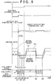
- a timing chart in FIG. 7 shows a case where the difference dTHC is smaller than 0 (dTHC ⁇ 0).
- the target air-fuel ratio AFt is corrected to be increased (S 118 to S122). Therefore, the fuel supply amount in a period from t12 to t13, a period from t14 to t15, or a period from t16 to t17 is smaller than the fuel supply amount in a time period from 110 to 111.
- the process in steps S118 to S122 in the air-fuel ratio feedback control calculation routine (FIG. 3) can be regarded as the reflection means.
- the process in step S132 and step S134 in the sulfur poisoning recovery control routine (FIG. 2) can be regarded as the learning means.
- step S132 in the sulfur poisoning recovery control routine (FIG. 2), it is determined whether the detected air-fuel ratio AF is in the reference air-fuel ratio range including the target air-fuel ratio AFt. Except for this, the second embodiment is the same as the first embodiment.
- the actual catalyst bed temperature THC becomes close to the target catalyst bed temperature THCt, and the detected air-fuel ratio AF also becomes close to the target air-fuel ratio AFt in the air-fuel ratio feedback control after the target air-fuel ratio AFt is corrected based on the deviation of the value detected by the air-fuel ratio sensor 48.
- the tentative learning value Gb corresponding to an appropriate air-fuel ratio feedback correction amount can be maintained as the learning value G.
- the detected air-fuel ratio AF is corrected using the difference dTHC between the target catalyst bed temperature THCt and the actual catalyst bed temperature THC. Accordingly, an air-fuel ratio feedback control calculation routine shown in FIG. 8 is performed instead of the air-fuel ratio feedback control calculation routine shown in FIG. 3.
- Other portions of the configuration of the third embodiment are the same as those in the first embodiment. Accordingly, the third embodiment will be described with reference also to FIG. 1 and FIG. 2.
- step S117 In the air-fuel ratio feedback control calculation routine (FIG. 8), a determination is made in step S117, instead of S116 in the routine shown in FIG 3. That is, it is determined that an absolute value of a difference between the target air-fuel ratio AFt and a corrected detected air-fuel ratio AFs is equal to or less than a value ds (
- the corrected detected air-fuel ratio AFs is set in step S123 that will be described later. However, the corrected detected air-fuel ratio AFs is initially set to the detected air-fuel ratio AF.
- step S 122 in the routine shown in FIG. 3 is deleted. Instead, step S123 is performed after step 120, and when a negative determination is made in step S117. Further, step S125 is performed, instead of step S124 in the routine shown in FIG. 3. Except for this, the routine shown in FIG. 8 is the same as the routine shown in FIG. 3. Accordingly, the same processes are denoted by the same step numbers.
- step S123 the corrected detected air-fuel ratio AFs is calculated by correcting the detected air-fuel ratio AF according to an equation 7. Equation ⁇ 7 AFs ⁇ AF - daft
- the target air-fuel ratio correction amount daft is practically used as a detected air-fuel ratio correction amount.
- the target air-fuel ratio correction amount daft is subtracted from the detected air-fuel ratio AF so that the corrected detected air-fuel ratio AFs becomes close to the actual air-fuel ratio, and finally the corrected detected air-fuel ratio AFs is set to the value that is equal to the actual air-fuel ratio.
- the difference E is calculated using the corrected detected air-fuel ratio AFs instead of the detected air-fuel ratio AF, according to an equation 8 described below. Equation ⁇ 8 E ⁇ AFs - AFt
- the corrected detected air-fuel ratio AFs becomes close to the actual air-fuel ratio at time t21 or t31.
- the corrected detected air-fuel ratio AFs becomes equal to the actual air-fuel ratio.
- the air-fuel ratio feedback control is performed based on substantially the actual air-fuel ratio.
- the process in steps S 118 to S123 in the air-fuel ratio feedback control calculation routine can be regarded as the reflection means
- the process in step 132 and step S134 in the sulfur poisoning recovery control routine (FIG. 2) can be regarded as the learning means.
Description
- The invention relates to a catalyst control apparatus for an internal combustion engine which performs a catalyst control for an exhaust gas control catalyst, by performing an air-fuel ratio feedback control for exhaust gas flowing into the exhaust gas control catalyst provided in an exhaust system of the internal combustion engine based on a value detected by an air-fuel ratio sensor provided in the exhaust system of the internal combustion engine, and a method for performing a catalyst control.
- Japanese Patent Laid-Open Publication No. 2000-274232 (JP-A-2000-274232) discloses an example of a technology in which an air-fuel ratio of exhaust gas is made rich so that sulfur components are discharged from an exhaust gas control catalyst when the exhaust gas control catalyst is poisoned with sulfur. In such a control for allowing the catalyst to recover from sulfur poisoning (hereinafter, referred to as "sulfur poisoning recovery control), when an air-fuel ratio of exhaust gas to be adjusted is deviated from a required air-fuel ratio, for example, the air-fuel ratio of exhaust gas may not be made sufficiently rich, sulfur components may not be sufficiently discharged, and the exhaust gas control catalyst may not be sufficiently recovered from sulfur poisoning. Also, when the air-fuel ratio of exhaust gas is made excessively rich, there is a possibility that white smoke and hydrogen sulfide (H2S) are discharged due to a large amount of hydrocarbon (hereinafter, referred to as "HC").
- In order to prevent the air-fuel ratio of exhaust gas from being deviated from a target air-fuel ratio, an oxygen concentration in the exhaust gas flowing into the exhaust gas control catalyst is detected using a sensor, and an air-fuel ratio feedback control is performed so that the air-fuel ratio of the exhaust gas becomes equal to an appropriate target air-fuel ratio based on the oxygen concentration in the aforementioned technology.
- However, when an air-fuel ratio sensor for detecting the air-fuel ratio is provided in an exhaust system in order to perform the aforementioned air-fuel ratio feedback control, and a value detected by the air-fuel ratio sensor is used, the value detected by the air-fuel ratio sensor may be deviated from the actual air-fuel ratio of exhaust gas due to a reason other than failure. For example, in the case where the air-fuel ratio sensor is provided downstream of the exhaust gas control catalyst, the molecular weight and molecular structure of HC in the exhaust gas that has passed through the exhaust gas control catalyst in which sulfur poisoning has progressed are different from those in the exhaust gas that has passed through the exhaust gas control catalyst in which sulfur poisoning has not progressed. Therefore, a diffusion rate of HC in the exhaust gas that has passed through the exhaust gas control catalyst in which sulfur poisoning has progressed is not always the same as that in the exhaust gas that has passed through the exhaust gas control catalyst in which sulfur poisoning has not progressed, even if the air-fuel ratio of the exhaust gas is the same. Since detection of the air-fuel ratio sensor is generally related to the diffusion rate of material to be measured, the detected value may become different due to the difference in the diffusion rate of HC even if the air-fuel ratio is the same.
- For example, when sulfur poisoning has progressed in the exhaust gas control catalyst, the value of the detected air-fuel ratio is high as compared to when sulfur poisoning has not progressed in the exhaust gas control catalyst, even if the air-fuel ratio of the same exhaust gas is detected. Therefore, in the case where the feedback control is performed for the air-fuel ratio of the exhaust gas flowing into the exhaust gas control catalyst using the air-fuel ratio sensor provided downstream of the exhaust gas control catalyst, the air-fuel ratio of exhaust gas is controlled to an air-fuel ratio lower than a required air-fuel ratio, since the value of the air-fuel ratio detected by the air-fuel ratio sensor is higher than the actual air-fuel ratio. Accordingly, a fuel concentration in the exhaust gas may be excessively high, and white smoke and hydrogen sulfide (H2S) may be discharged.
- Meanwhile, when sulfur poisoning has not progressed, the value of the detected air-fuel ratio is low as compared to when sulfur poisoning has progressed to some extent, even if the air-fuel ratio of the same exhaust gas is detected. Therefore, the air-fuel ratio of exhaust gas is controlled to an air-fuel ratio higher than the required air-fuel ratio. Accordingly, there is a possibility that the air-fuel ratio is not made sufficiently rich, and the exhaust gas control catalyst cannot sufficiently recover from sulfur poisoning.
- Such deviation of the detected value of the air-fuel ratio sensor varies depending on the HC concentration in the exhaust gas. Even in the case where the air-fuel ratio sensor is provided upstream of the exhaust gas control catalyst, there is a possibility that the air-fuel ratio feedback control is not appropriately performed due to the aforementioned phenomenon.
- It is an object of the invention to enable an air-fuel ratio feedback control to be appropriately performed even if a value detected by an air-fuel ratio sensor provided in an exhaust system is deviated from an actual air-fuel ratio.
- A first aspect of the invention relates to a catalyst control apparatus for an internal combustion engine, which performs a catalyst control for an exhaust gas control catalyst, by performing an air-fuel ratio feedback control for exhaust gas flowing into the exhaust gas control catalyst provided in an exhaust system of the internal combustion engine based on a value detected by an air-fuel ratio sensor provided in the exhaust system of the internal combustion engine. The catalyst control apparatus includes detection means for detecting a bed temperature of the exhaust gas control catalyst; and reflection means for obtaining a degree of deviation between an actual air-fuel ratio estimated based on the bed temperature of the exhaust gas control catalyst, that is detected if the exhaust gas control catalyst is in a reference state, and a value detected by the air-fuel ratio sensor, based on the detected bed temperature (THC) of the exhaust gas control catalyst.
- Reaction heat in the exhaust gas control catalyst varies, and accordingly the bed temperature of the catalyst varies depending on an amount of oxidation components such as HC in the exhaust gas. Influence of the diffusion rate of HC on the bed temperature of the catalyst is smaller than influence of the diffusion rate of HC on the air-fuel ratio sensor. Therefore, the deviation between the air-fuel ratio estimated based on the bed temperature of the catalyst detected by the detection means, and the value detected by the air-fuel ratio sensor, or the deviation between the bed temperature of the catalyst detected by the detection means and the bed temperature of the catalyst corresponding to the value detected by the air-fuel ratio sensor reflects the deviation between the actual air-fuel ratio and the air-fuel ratio detected by the air-fuel ratio sensor.
- Accordingly, the reflection means can obtain the degree of the deviation between the actual air-fuel ratio and the value detected by the air-fuel ratio sensor based on the detected bed temperature of the catalyst, and can reflect the obtained degree of the deviation in the air-fuel ratio feedback control.
- Thus, the air-fuel ratio feedback control can be appropriately performed even if the value detected by the air-fuel ratio sensor provided in the exhaust system is deviated. The air-fuel ratio feedback control may be performed by adjusting at least one of an amount of fuel supplied to the exhaust system from a supply valve, and an amount of fuel injected into a combustion chamber during an expansion stroke or an exhaust stroke.
- The air-fuel ratio feedback control for the exhaust gas flowing into the exhaust gas control catalyst may be performed by adjusting at least one of the amount of fuel supplied to the exhaust system and the amount of fuel injected into the combustion chamber in the aforementioned manner.
- The reflection means may obtain, as the degree of the deviation, a temperature difference between a target bed temperature of the catalyst that is set according to an operating state of the internal combustion engine and the detected bed temperature of the catalyst, and may reflect the temperature difference in the catalyst control.
- The bed temperature of the exhaust gas control catalyst is basically decided by the temperature of the exhaust gas flowing thereto, and increases due to reaction heat caused by HC and the like. Accordingly, even if the air-fuel ratio of the exhaust gas is adjusted in order to make the bed temperature of the catalyst equal to the target bed temperature of the catalyst that is set according to the operating state of the internal combustion engine, when there is a difference between the actual air-fuel ratio and the value detected by the air-fuel ratio sensor, the actual bed temperature of the catalyst does not become equal to the target bed temperature of the catalyst. As a result, there is a difference between the actual bed temperature of the catalyst and the target bed temperature of the catalyst according to the aforementioned deviation. Accordingly, the reflection means obtains the temperature difference between the target bed temperature of the catalyst and the actual bed temperature of the catalyst as the degree of the deviation, thereby reflecting the degree of the deviation in the air-fuel ratio feedback control. Thus, the air-fuel ratio feedback control can be appropriately performed even if the value detected by the air-fuel ratio sensor provided in the exhaust system is deviated.
- The reflection means may correct a target air-fuel ratio in the air-fuel ratio feedback control based on the degree of the deviation.
- The degree of the deviation can be reflected by correcting the target air-fuel ratio. Even if there is a deviation between the actual air-fuel ratio and the value detected by the air-fuel ratio sensor, since the target air-fuel ratio is changed by correction, the deviation is cancelled by an amount by which the target air-fuel ratio is corrected, whereby the actual air-fuel ratio can be made equal to the required air-fuel ratio. Thus, the air-fuel ratio feedback control can be appropriately performed even if the value detected by the air-fuel ratio sensor provided in the exhaust system is deviated.
- The reflection means may correct the target air-fuel ratio in the air-fuel ratio feedback control to a higher value as an absolute value of the temperature difference becomes larger when the detected bed temperature of the catalyst is higher than the target bed temperature of the catalyst, and may correct the target air-fuel ratio to a lower value as the absolute value of the temperature difference becomes larger when the detected bed temperature of the catalyst is lower than the target bed temperature of the catalyst.
- When the actual bed temperature of the catalyst is higher than the target bed temperature of the catalyst, the amount of reaction heat in the exhaust gas control catalyst is excessively large although the target air-fuel ratio is set so that the target temperature of the catalyst is achieved, and the air-fuel ratio feedback control is performed so that the value detected by the air-fuel ratio sensor becomes equal to the target air-fuel ratio. This signifies that the actual air-fuel ratio is lower than the target air-fuel ratio. Accordingly, the air-fuel ratio feedback control adjusts the air-fuel ratio to a higher value by correcting the target air-fuel ratio to a higher value according to the absolute value of the difference between the target bed temperature of the catalyst and the detected bed temperature of the catalyst. Accordingly, it is possible to eliminate the situation in which the actual air-fuel ratio is lower than the target air-fuel ratio when the exhaust gas control catalyst is in a reference state (hereinafter, referred to as "original target air-fuel ratio"). Thus, the actual air-fuel ratio becomes close to the original target air-fuel ratio.
- Meanwhile, when the actual bed temperature of the catalyst is lower than the target bed temperature of the catalyst, the amount of reaction heat in the exhaust gas control catalyst is insufficient although the target air-fuel ratio is set so that the target temperature of the catalyst is achieved, and the air-fuel ratio feedback control is performed so that the value detected by the air-fuel ratio sensor becomes equal to the target air-fuel ratio. This signifies that the actual air-fuel ratio is higher than the target air-fuel ratio. Accordingly, the air-fuel ratio feedback control adjusts the air-fuel ratio to a lower value by correcting the target air-fuel ratio to a lower value according to the absolute value of the temperature difference between the target bed temperature of the catalyst and the detected bed temperature of the catalyst. Accordingly, it is possible to eliminate the situation in which the actual air-fuel ratio is higher than the original target air-fuel ratio. Thus, the actual air-fuel ratio becomes close to the original target air-fuel ratio. Thus, the air-fuel ratio feedback control can be appropriately performed even if the value detected by the air-fuel ratio sensor provided in the exhaust system is deviated.
- The catalyst control apparatus may further include learning means for maintaining an air-fuel ratio feedback correction amount in the air-fuel ratio feedback control as a learning value when the detected bed temperature of the catalyst is in a reference bed temperature range including the target bed temperature of the catalyst.
- The learning means maintains the air-fuel ratio feedback correction amount as the learning value when the detected bed temperature of the catalyst is in the reference bed temperature range including the target bed temperature of the catalyst. Thus, learning is prevented from being performed while the actual air-fuel ratio is deviated from the original target air-fuel ratio, and accordingly learning is performed while the actual air-fuel ratio is close to the original target air-fuel ratio. Therefore, it is possible to obtain an appropriate learning value having a small error, and to perform the air-fuel ratio feedback control with high accuracy.
- The catalyst control apparatus may further include learning means for maintaining an air-fuel ratio feedback correction amount in the air-fuel ratio feedback control as a learning value when the value detected by the air-fuel ratio sensor is in a reference air-fuel ratio range including the corrected target air-fuel ratio.
- The learning means maintains the air-fuel ratio feedback correction amount as the learning value when the detected value of the air-fuel ratio sensor is in the reference air-fuel ratio range including the corrected target air-fuel ratio. Thus, since learning is performed while the actual air-fuel ratio is close to the original target air-fuel ratio, it is possible to obtain an appropriate learning value having a small error, and to perform the air-fuel ratio feedback control with high accuracy, even if the value detected by the air-fuel ratio sensor is deviated.
- In the catalyst control apparatus, the reflection means may correct the value detected by the air-fuel ratio sensor based on the degree of the deviation.
- The degree of the deviation can be reflected in the catalyst control by correcting the value detected by the air-fuel ratio sensor. Since the value detected by the air-fuel ratio sensor is changed by correction, the deviation between the actual air-fuel ratio and the value detected by the air-fuel ratio sensor can be reduced by correcting the value detected by the air-fuel ratio sensor, even if there is a deviation between the actual air-fuel ratio and the value detected by the air-fuel ratio sensor. Thus, the actual air-fuel ratio can be accurately detected. As a result, the air-fuel ratio feedback control can be appropriately performed even if the value detected by the air-fuel ratio sensor provided in the exhaust system is deviated.
- The reflection means may correct the value detected by the air-fuel ratio sensor to a lower value as an absolute value of the difference becomes larger when the detected bed temperature of the catalyst is higher than the target bed temperature of the catalyst, and may correct the value detected by the air-fuel ratio sensor to a higher value as the absolute value of the difference is larger when the detected bed temperature of the catalyst is lower than the target bed temperature of the catalyst.
- When the actual bed temperature of the catalyst is higher than the target bed temperature of the catalyst, the amount of reaction heat in the exhaust gas control catalyst is excessively large although the target air-fuel ratio is set so that the target temperature of the catalyst is achieved, and the air-fuel ratio feedback control is performed so that the value detected by the air-fuel ratio sensor becomes equal to the target air-fuel ratio. This signifies that the actual air-fuel ratio is lower than the target air-fuel ratio. Accordingly, the actual air-fuel ratio can be accurately obtained by correcting the value detected by the air-fuel ratio sensor to a lower value according to the absolute value of the difference between the target bed temperature of the catalyst and the detected bed temperature of the catalyst. Therefore, the air-fuel ratio feedback control can accurately adjust the actual air-fuel ratio. Thus, the actual bed temperature of the catalyst becomes close to the target bed temperature of the catalyst.
- When the actual bed temperature of the catalyst is lower than the target bed temperature of the catalyst, the amount of reaction heat in the exhaust gas control catalyst is insufficient although the target air-fuel ratio is set so that the target temperature of the catalyst is achieved, and the air-fuel ratio feedback control is performed so that the value detected by the air-fuel ratio sensor becomes equal to the target air-fuel ratio. This signifies that the actual air-fuel ratio is higher than the target air-fuel ratio. Accordingly, the actual air-fuel ratio can be accurately obtained by correcting the value detected by the air-fuel ratio sensor to a higher value according to the absolute value of the difference between the target bed temperature of the catalyst and the detected bed temperature of the catalyst. Therefore, the air-fuel ratio feedback control can accurately adjust the actual air-fuel ratio. Thus, the actual bed temperature of the catalyst becomes close to the target bed temperature of the catalyst. Thus, the air-fuel ratio feedback control can be appropriately performed even if the value detected by the air-fuel ratio sensor provided in the exhaust system is deviated.
- In the case where the value detected by the air-fuel ratio sensor is corrected as well, the catalyst control apparatus may include learning means for maintaining an air-fuel ratio feedback correction amount in the air-fuel ratio feedback control as a learning value when the detected bed temperature of the catalyst is in a reference bed temperature range including the target bed temperature of the catalyst.
- The learning means maintains the air-fuel ratio feedback correction amount as the learning value when the detected bed temperature of the catalyst is in the reference bed temperature range including the target bed temperature of the catalyst. Thus, since the value detected by the air-fuel ratio sensor is accurately corrected to the actual air-fuel ratio, learning is prevented from being performed while the actual air-fuel ratio is deviated from the target air-fuel ratio, and accordingly learning is performed while the actual air-fuel ratio is accurately close to the target air-fuel ratio. Therefore, it is possible to obtain an appropriate learning value having a small error, and to perform the air-fuel ratio feedback control with high accuracy.
- The catalyst control apparatus may include learning means for maintaining an air-fuel ratio feedback correction amount in the air-fuel ratio feedback control as a learning value when the corrected detected value is in a reference air-fuel ratio range including the target air-fuel ratio in the air-fuel ratio feedback control.
- The learning means maintains the air-fuel ratio feedback correction amount as the learning value when the corrected detected value is in the reference air-fuel ratio range including the target air-fuel ratio. Thus, even if the value detected by the air-fuel ratio sensor is deviated, since learning is performed while the actual air-fuel ratio is close to the target air-fuel ratio, it is possible to obtain an appropriate learning value having a small error, and to perform the air-fuel ratio feedback control with high accuracy.
- The exhaust gas control catalyst may be a NOx storage reduction catalyst.
- The internal combustion engine may be a diesel engine.
- A second aspect of the invention relates to a method for performing a catalyst control for an exhaust gas control catalyst by performing an air-fuel ratio feedback control for exhaust gas flowing into the exhaust gas control catalyst provided in an exhaust system of the internal combustion engine based on a value detected by an air-fuel ratio sensor provided in the exhaust system of the internal combustion engine. The method for performing a catalyst control includes the steps of detecting a bed temperature of the exhaust gas control catalyst; and obtaining a degree of deviation between an actual air-fuel ratio that is detected if the exhaust gas control catalyst is in a reference state and a value detected by the air-fuel ratio sensor based on the detected bed temperature of the exhaust gas control catalyst, and reflecting the obtained degree of the deviation in the catalyst control.
- The foregoing and further objects, features and advantages of the invention will become apparent from the following description of preferred embodiments with reference to the accompanying drawings, wherein like numerals are used to represent like elements and wherein:
- FIG. 1 is a block diagram showing a schematic configuration of a control system that functions as a catalyst control apparatus for a diesel engine for a vehicle according to a first embodiment of the invention;
- FIG. 2 is a flow chart of a sulfur poisoning recovery control routine performed by an ECU in the first embodiment of the invention;
- FIG. 3 is a flow chart of an air-fuel ratio feedback control calculation routine in the first embodiment of the invention;
- FIG. 4 is a timing chart showing an example of a control according to the first embodiment of the invention;
- FIG. 5 is a graph showing a configuration of a target air-fuel ratio correction amount map Mapaft:
- FIG. 6 is a graph showing a configuration of a coefficient map Mapf;
- FIG. 7 is a timing chart showing another example of the control according to the first embodiment of the invention;
- FIG. 8 is a flow chart of an air-fuel ratio feedback control calculation routine according to a third embodiment of the invention;
- FIG. 9 is a timing chart showing an example of a control according to a third embodiment of the invention; and
- FIG. 10 is a timing chart showing another example of the control according to the third embodiment of the invention.
- FIG. 1 is a block diagram showing a schematic configuration of a diesel engine for a vehicle according to a first embodiment of the invention, and a control system that functions as a catalyst control apparatus. The invention can be applied in the case where a catalyst having a similar configuration is employed in a lean-burn engine or the like.
- A
diesel engine 2 includes plural cylinders. In this case, thediesel engine 2 includes fourcylinders # 1, #2, #3, and #4. Acombustion chamber 4 in each of thecylinders # 1, #2, #3, and #4 is connected to a surge tank 12 via an intake port 8 that is opened and closed by anintake valve 6, and an intake manifold. The surge tank 12 is connected to anintercooler 14 and an outlet side of acompressor 16a of a supercharger (in this case, an exhaust gas turbocharger 16) via an intake passage 13. An inlet side of thecompressor 16a is connected to anair cleaner 18. An exhaust gas recirculation (hereinafter, referred to as "EGR")supply port 20a of anEGR passage 20 is opened to the surge tank 12. Athrottle valve 22 is provided in an intake passage 13 between the surge tank 12 and theintercooler 14. An intakeair amount sensor 24 and an intakeair temperature sensor 26 are provided between thecompressor 16a and theair cleaner 18. - The
combustion chamber 4 of each of thecylinders # 1, #2, #3, and #4 is connected an inlet side of anexhaust turbine 16b of theexhaust turbocharger 16 via anexhaust port 30 that is opened and closed by anexhaust valve 28, and anexhaust manifold 32. An outlet side of theexhaust turbine 16b is connected to anexhaust passage 34. Exhaust gas is introduced to theexhaust turbine 16b from thefourth cylinder # 4 side of theexhaust manifold 32. - Three catalyst converters, that are, a
first catalyst converter 36, asecond catalyst converter 38, athird catalyst converter 40 are provided in theexhaust passage 34 in this order in a direction from an upstream side to a downstream side. An exhaust gas control catalyst is housed in each of the catalyst converters. A NOxstorage reduction catalyst 36a is housed in thefirst catalyst converter 36. When the exhaust gas is in an oxidation atmosphere (that is, the air-fuel ratio of the exhaust gas is lean) while thediesel engine 2 is normally operated, NOx is stored in thestorage reduction catalyst 36a. When the exhaust gas is in a reduction atmosphere (that is, the air-fuel ratio of the exhaust gas is equal to a stoichiometric air-fuel ratio, or lower than the stoichiometric air-fuel ratio), the NOx stored in the NOxstorage reduction catalyst 36a is discharged as NO, and NO is reduced by HC and CO. Thus, NOx is removed. - A
filter 38a including a wall portion which is formed to have a monolith structure is housed in thesecond catalyst converter 38. Exhaust gas passes through micropores in the wall portion. A layer of the NOx storage reduction catalyst is formed by coating on the surfaces of the micropores in thefilter 38a which is a substrate. Thus, thefilter 38a functions as the exhaust gas control catalyst, and NOx is removed in the filter in the manner described above. Also, the wall portion of thefilter 38a captures particulate matter (hereinafter, referred to as "PM"). Therefore, PM starts to be oxidized due to active oxygen that is generated when NOx is stored in the oxidation atmosphere at high temperatures. Further, the entire PM is oxidized due to an excessive amount of oxygen therearound. Thus, PM is removed while NOx is removed. Thefirst catalyst converter 36 and thesecond catalyst converter 38 are formed so as to be integrated with each other. - An
oxidation catalyst 40a is housed in thethird catalyst converter 40. HC and CO are oxidized so as to be removed in thethird catalyst converter 40. A first exhaustgas temperature sensor 44 is provided between the NOxstorage reduction catalyst 36a and thefilter 38a. A second exhaustgas temperature sensor 46 is provided near thefilter 38a, and an air-fuel ratio sensor 48 is provided near theoxidation catalyst 40a between thefilter 38a and theoxidation catalyst 40a. - The air-
fuel ratio sensor 48 is formed using solid electrolyte. The air-fuel ratio sensor 48 detects the air-fuel ratio of the exhaust gas based on exhaust gas components, that is, HC components, and linearly outputs a voltage signal which is proportional to the air-fuel ratio. The first exhaustgas temperature sensor 44 detects an exhaust gas temperature Texin at the position thereof. The second exhaustgas temperature sensor 46 detects an exhaust gas temperature Texout at the position thereof. The exhaust gas temperature Texout is the temperature of the exhaust gas immediately after flowing out of thefilter 38a. Thus, the exhaust gas temperature Texout corresponds to the bed temperature of thefilter 38a. Accordingly, the second exhaustgas temperature sensor 46 can be regarded as detection means. - Each pipe of a
pressure difference sensor 50 is provided on an upstream side and a downstream side of thefilter 38a. Thedifferential pressure sensor 50 detects a pressure difference ΔP between the upstream side and the downstream side of thefilter 38a so as to detect the degree of clogging of thefilter 38a, that is, the degree of accumulation of PM. - An EGR
gas intake port 20b of theEGR passage 20 is opened to theexhaust manifold 32. The EGRgas intake port 20b is opened on thefirst cylinder # 1 side which is opposed to thefourth cylinder # 4 side from which the exhaust gas is introduced to theexhaust turbine 16b. - In the
EGR passage 20, aniron EGR catalyst 52 for reforming the EGR gas, and anEGR cooler 54 for cooling the EGR gas are provided in this order from the EGRgas intake port 20b side. TheEGR catalyst 52 has a function of preventing the EGR cooler 54 from being clogged. Also, anEGR valve 56 is disposed on an EGRgas supply port 20a side. The amount of the EGR gas supplied from the EGRgas supply port 20a to the intake system can be adjusted by adjusting the opening amount of theEGR valve 56. - Each fuel injection valve 58 which directly injects fuel into each
combustion chamber 4 is provided for each of thecylinders # 1 to #4. Each fuel injection valve 58 is connected to a common rail 60 via afuel supply pipe 58a. The fuel is supplied into the common rail 60 from an electrically controlledfuel pump 62 whose discharge amount is variable. High-pressure fuel supplied into the common rail 60 from thefuel pump 62 is distributed to each fuel injection valve 58 via eachfuel supply pipe 58a. A fuel pressure sensor 64 for detecting the pressure of fuel is fitted to the common rail 60. - Further, low-pressure fuel is separately supplied to the
supply valve 68 from thefuel pump 62 via a fuel supply pipe 66. Thesupply valve 68 is provided in theexhaust port 30 of thefourth cylinder # 4. Thesupply valve 68 injects the fuel toward theexhaust turbine 16b side, thereby supplying the fuel into the exhaust gas. A catalyst control mode that will be described later is performed by supplying the fuel into exhaust gas. - An electronic control unit (hereinafter, referred to as "ECU") 70 mainly includes a digital computer and a driving circuit. The digital computer includes a CPU, ROM, RAM, and the like. The driving circuit drives various devices. The
ECU 70 reads signals from the intakeair amount sensor 24, the intakeair temperature sensor 26, the first exhaustgas temperature sensor 44, the second exhaustgas temperature sensor 46, the air-fuel ratio sensor 48, thepressure difference sensor 50, an EGR opening amount sensor in theEGR valve 56, the fuel pressure sensor 64, and the throttleopening amount sensor 22a. Also, theECU 70 reads signals from an acceleratoropening amount sensor 74 for detecting a depression amount of an accelerator pedal 72 (an accelerator opening amount ACCP), and acoolant temperature sensor 76 for detecting a coolant temperature THW of thediesel engine 2. Further, theECU 70 reads signals from an enginerotational speed sensor 80 for detecting a rotational speed NE of acrank shaft 78, and acylinder discrimination sensor 82 for detecting a rotational phase of thecrank shaft 78 or a rotational phase of an intake cam so as to perform cylinder discrimination. - The
ECU 70 controls a fuel injection amount and fuel injection timing using the fuel injection valve 58 based on the engine operating state obtained from these signals. Further, theECU 70 controls the opening amount of theEGR valve 56, the throttle valve opening amount using amotor 22b, the discharge amount of thefuel pump 62, and opening of thesupply valve 68, thereby performing a PM removal control and a sulfur poisoning recovery control that will be described later, and the like. - As a combustion mode control, the
ECU 70 selects and performs a combustion mode from among two combustion modes, that are, a normal combustion mode and a low temperature combustion mode, according to the operating state. In the low temperature combustion mode, NOx and smoke are simultaneously reduced by making an exhaust gas recirculation amount large according to an EGR valve opening amount map for the low temperature combustion mode so as to decrease the degree of an increase in a combustion temperature. The low temperature combustion mode is performed in a low load low-to medium rotational speed region, and the air-fuel ratio feedback control is performed by adjusting a throttle opening amount TA based on an air-fuel ratio AF detected by the air-fuel ratio sensor 48. Another combustion mode is the normal combustion mode in which a normal EGR control is performed according to an EGR valve opening amount map for the normal combustion mode. In the normal combustion mode, there is a possibility that exhaust gas recirculation is not performed. - As the catalyst control mode of the catalyst control for the exhaust gas control catalyst, there are four modes, that are, the PM removal control mode, the sulfur poisoning recovery control mode, a NOx reduction control mode, and a normal control mode. In the PM removal control mode, PM accumulated particularly in the
filter 38a in thesecond catalyst converter 38 is burned by increasing the bed temperature of thefilter 38a as described above so that PM is changed to CO2 and H2O, and then CO2 and H2O are discharged. In this mode, the bed temperature of thefilter 38a is increased to a high temperature (for example, 600 to 700 °C) by repeatedly supplying the fuel from thesupply valve 68 at the air-fuel ratio higher than the stoichiometric air-fuel ratio. Further, in this mode, the fuel may be injected into thecombustion chamber 4 from the fuel injection valve 58 during the expansion stroke or the exhaust stroke, that is, so-called after-injection may be performed. - In the sulfur poisoning recovery control mode, sulfur components are discharged so that the NOx
storage reduction catalyst 36a and thefilter 38a recovers from sulfur poisoning when the NOxstorage reduction catalyst 36a and thefilter 38a are poisoned with sulfur and the NOx storage capacity is decreased. In this mode, a temperature increase process and an air-fuel ratio decrease process are performed. In the temperature increase process, the bed temperatures of the NOxstorage reduction catalyst 36a and thefilter 38a (hereinafter, referred to as "catalyst bed temperature") are increased to a high temperature (for example, 650 °C) by repeatedly supplying the fuel from thesupply valve 68. In the air-fuel ratio decrease process, the air-fuel ratio is made equal to, or slightly lower than the stoichiometric air-fuel ratio by intermittently supplying the fuel from thesupply valve 68 as described later. In the embodiment, the air-fuel ratio is made slightly lower than the stoichiometric air-fuel ratio, that is, the air-fuel ratio is made rich. In this mode as well, the after-injection may be performed by the fuel injection valve 58. - In the NOx reduction control mode, NOx stored in the NOx
storage reduction catalyst 36a and thefilter 38a is reduced to N2, CO2, and H2O, and then N2, CO2, and H2O are discharged. In this mode, the catalyst bed temperature is made relatively low (for example, 250 to 500 °C), and the air-fuel ratio is made equal to, or lower than the stoichiometric air-fuel ratio by intermittently supplying the fuel from thesupply valve 68 at relatively long time intervals. - A catalyst control mode other than these three modes is the normal control mode. In the normal control mode, the fuel is not supplied from the
supply valve 68, and the after-injection is not performed by the fuel injection valve 58. - Next, the sulfur poisoning recovery control routine, which is one of the catalyst control routines performed by the
ECU 70 according to the embodiment, will be described. FIG. 2 and FIG. 3 show a flowchart of the control routine. The control routine is performed as an interrupt at given time intervals. When the control routine is started, first, it is determined whether a sulfur poisoning recovery control condition is satisfied (S 102). The sulfur poisoning recovery control condition is used for determining whether the sulfur poisoning recovery control should be started. For example, the sulfur poisoning recovery control condition includes a condition that a sulfur poisoning amount has reached a sulfur discharge control determination value, and the PM removal control mode is not performed. Further, the sulfur poisoning recovery control condition includes a condition that the aforementioned temperature increase process required for recovery from sulfur poisoning has been completed, and both of the bed temperature of the NOxstorage reduction catalyst 36a and the bed temperature of thefilter 38a that are determined based on the exhaust gas temperatures Texin, Texout, are in a temperature range excluding a low temperature state range and an overheat state range. - If the sulfur poisoning recovery control condition is not satisfied (i.e., NO in step S102), the routine is terminated. If the sulfur poisoning recovery control condition is satisfied (i.e., YES in step S102), it is determined whether the first routine is being performed after the sulfur poisoning recovery control condition is satisfied (S104). If the first routine is being performed (i.e., YES in step S104), a fuel supply amount A1 (mm3) is calculated according to an
equation 1, and then, a fuel supply time interval B (ms), a fuel supply time period C (sec), and a fuel supply pause time period D (sec) are calculated (S106).
- The base supply amount Ab (mm3) is the amount of the fuel that needs to be supplied from the
supply valve 68 in order to achieve the target air-fuel ratio required for recovery from sulfur poisoning, with respect to the air-fuel ratio of the exhaust gas discharged from thedischarge port 30 when the sulfur poisoning recovery control is performed. The air-fuel ratio of the exhaust gas discharged from theexhaust port 30 is decided based on a relation between the amount of the fuel injected from the fuel injection valve 58 (corresponding to the engine load) and an intake air amount GA detected by the intakeair amount sensor 24. Accordingly, the base supply amount Ab (mm3) is calculated based on the amount of the fuel injected from the fuel injection valve 58 and the intake air amount GA according to a map. The map is made in advance by obtaining the fuel supply amount for achieving the aforementioned target air-fuel ratio based on the engine in a reference state through experiments. The map is stored in the memory in theECU 70. A learning value G is initially set to "1". The learning value G is renewed by learning a correction amount in the air-fuel ratio feedback control as described later. The learning value G is stored and maintained in a non-volatile memory such as a backup RAM and a flash memory. - The supply time interval B, the supply time period C, and the supply pause time period D are as shown in the timing chart in FIG. 4. The timing chart in FIG. 4 shows a case where the fuel is supplied from the
supply valve 68 four times in succession during valve opening time periods a1 to a4 at the supply time intervals B during the supply time period C, and then the fuel is supplied four times in succession again after the supply pause time period D elapses. The values of the supply time interval B, the supply time period C, and the supply pause time period D are appropriately set for the sulfur poisoning recovery control, based on the sulfur poisoning amount, the inflow exhaust gas temperature (exhaust gas temperature Texin), the catalyst bed temperature (the exhaust temperature Texout is used as a substitute value), and the like in the NOxstorage reduction catalyst 36a and thefilter 38a. The valve opening time period a1 of thesupply valve 68 during the supply time period C corresponds to an actual fuel supply amount Ar described below. - Next, a tentative learning value Gb that will be described later is set to the learning value G (S107). Then, the actual fuel supply amount Ar is set to the fuel supply amount A1 calculated according to the equation 1 (S108).
- Next, it is determined whether a fuel supply determination condition is satisfied (S110). The fuel supply determination condition is satisfied when the supply time period C has not elapsed, and the bed temperature of the NOx
storage reduction catalyst 36a and the bed temperature of thefilter 38a are not in the overheat state range. If the fuel supply determination condition is satisfied (i.e., YES in step S 110), it is determined whether a start time of the fuel supply has been reached, that is, a start time of the valve opening time period a1 of thesupply valve 68 has been reached (S111). - If the first fuel supply in the sulfur poisoning recovery control has not been performed, the start time of the fuel supply has been reached (i.e., YES in step S111), and therefore the fuel supply for the sulfur poisoning recovery control is performed (during the valve opening time period a1) (S112). Thus, the fuel of the actual fuel supply amount Ar set in steps S106 and 108 is supplied as the first fuel supply in the sulfur poisoning recovery control. In the timing chart in FIG. 4, the fuel supply is started at time t0, and the fuel supply is performed by opening the
supply valve 68 until time t1. - Subsequent to step S 112, an air-fuel ratio feedback control calculation routine shown in FIG. 3 is performed (S 114). It is determined whether a finish time of the valve opening time period a1 of the
supply valve 68 has been reached (S115). In the case shown in FIG. 4, since the valve opening time period a1 has just started (i.e., NO in step S115), the air-fuel ratio feedback control calculation routine (FIG. 3) is immediately finished. - In a next control cycle, if the sulfur poisoning recovery control condition continues to be satisfied (i.e., YES in step S102), the second routine is being performed after the sulfur poisoning recovery control condition is satisfied (i.e., NO in step S104). Therefore, a determination is made in step S110. If the supply time period C has not elapsed, and therefore the fuel supply determination condition is satisfied (i.e., YES in step S110), it is determined whether the start time of the fuel supply has been reached (S111). Since the valve opening time period a1 of the
supply valve 68 has not elapsed (a period from t0 to t1 has not elapsed in FIG. 4), and the fuel supply has already been started (i.e., NO in step S111), the air-fuel ratio feedback control calculation routine is immediately started (S 114). However, since the valve opening time period a1 has not elapsed (i.e., NO in step S 115 in FIG. 3), the air-fuel ratio feedback control calculation routine (FIG. 3) is immediately finished. - After the routine is repeated, an affirmative determination is made in step S 115 in the air-fuel ratio feedback control calculation routine (FIG. 3) when the finish time of the valve opening time period a1 has been reached (at t1 in FIG. 4). Accordingly, it is determined whether an absolute value of a difference between a target air-fuel ratio AFt and a detected air-fuel ratio AF that is a value detected by the air-
fuel ratio sensor 48 is equal to or less than a value ds. The value ds indicates a reference range whose center is zero (S 116). The target air-fuel ratio AFt is initially set as an air-fuel ratio at which the NOxstorage reduction catalyst 36a and thefilter 38a can recover from sulfur poisoning. The target air-fuel ratio AFt is renewed by a correction process (S 118 to S122) that will be described later. - If the detected air-fuel ratio AF is not sufficiently close to the target air-fuel ratio AFt, that is, the absolute value of the difference therebetween is greater than the value ds (|AFt - AF|> ds) (i.e., NO in step S 116), the routine proceeds to step S124. FIG. 4 shows the case where the detected air-fuel ratio AF is sufficiently close to the target air-fuel ratio AFt at time t1. In this case, the absolute value of the difference therebetween is equal to or less than the value ds (|AFt - AF| ≤ ds) (i.e., YES in step S116), a difference dTHC between a target catalyst bed temperature THCt and an actual catalyst bed temperature THC in the NOx
storage reduction catalyst 36a and thefilter 38a is calculated according to anequation 2 described below (S 118).
- In this
equation 2, the target catalyst bed temperature THCt is a catalyst bed temperature required for recovery from sulfur poisoning. For example, the target catalyst bed temperature THCt is set in advance in a range of 600 °C to 700 °C. Since the actual catalyst bed temperature THC is not directly measured in the embodiment, the exhaust gas temperature Texout is used as a substitute value. The exhaust gas temperature Texout is output from the second exhaustgas temperature sensor 46 for measuring the temperature of the exhaust gas immediately after discharged from thefilter 38a of thesecond catalyst converter 38. - Next, a target air-fuel ratio correction amount daft which is used for correcting the target air-fuel ratio AFt is calculated based on the aforementioned difference dTHC (°C) according to a target air-fuel ratio correction amount map Mapaft (S120). The target air-fuel ratio correction amount map Mapaft is as shown in FIG. 5. As shown in FIG. 5, when the difference dTHC is larger than 0 (dTHC > 0), the target air-fuel ratio correction amount daft is set to a value which is equal to or greater than -0.1 and less than 0, according to the difference dTHC. When the difference dTHC is smaller than 0 (dTHC > 0), the target air-fuel ratio correction amount daft is set to a value which is greater than 0 and is equal to or less than 0.1, according to the difference dTHC. When the difference dTHC = 0, the target air-fuel ratio correction amount daft = 0.
- Next, the target air-fuel ratio AFt is corrected using the target air-fuel ratio correction amount daft according to an
equation 3, and is renewed (S122).
- The AFt on the right side indicates the target air-fuel ratio before renewal.
- Accordingly, when the target catalyst bed temperature THCt is higher than the actual catalyst bed temperature THC (THCt > THC), the target air-fuel ratio AFt is corrected to be decreased. When the target catalyst bed temperature THCt is lower than the actual catalyst bed temperature THC (THCt < THC), the target air-fuel ratio AFt is corrected to be increased.
- Thus, in the case where the detected air-fuel ratio AF is sufficiently close to the target air-fuel ratio AFt at the finish time of the valve opening time period a1, the target air-fuel ratio AFt is renewed based on the difference dTHC between the target catalyst bed temperature THCt and the actual catalyst bed temperature THC. In the case shown in FIG. 4, since the target catalyst bed temperature THCt is higher than the actual catalyst bed temperature THC at time t1, the target air-fuel ratio AFt is corrected to be decreased as shown by an arrow in the time chart for the air-fuel ratio in FIG. 4.
- Next, a difference E between the detected air-fuel ratio AF and the target air-fuel ratio AFt is calculated according to an
equation 4 described below (S124).
- The difference E is obtained using the target air-fuel ratio AFt which has been corrected to be decreased at time t1 in FIG. 4 in step S122.
- Next, a coefficient F corresponding to the air-fuel ratio feedback correction amount is calculated based on the difference E according to a coefficient map Mapf shown in FIG. 6 (S126). As shown in FIG. 6, when the difference E is larger than 0 (E > 0), the coefficient F is set to a value which is greater than 1 and is equal to or less than 1.2, according to the difference E. When the difference is less than 0 (E < 0), the coefficient F is set to a value which is equal to or greater than 0.8, and is less than 1, according to the difference E. When the difference E is 0 (E = 0), the coefficient F is set to 1.
- Next, the tentative learning value Gb is calculated according to an equation 5 described below (S 127).

- In this equation 5, the tentative learning value Gb is set to the learning value G as an initial value, as described above.
- Next, a new actual fuel supply amount Ar is calculated based on a product of the base supply amount Ab and the tentative learning value Gb, according to an
equation 6 described below (S128). The base supply amount Ab is obtained using the map in step S106 as described above.
- Since the target air-fuel ratio AFt that has been corrected to be decreased at time t1 in FIG. 4 is used, the coefficient F is set to a value greater than 1, the tentative learning value Gb is increased. Therefore, at time t1, the actual fuel supply amount Ar is set to a value greater than a previous value in the period from t0 to t1.
- Thus, the air-fuel ratio feedback control calculation routine (S 114) is finished. A next control cycle is performed during the supply time interval B (tl to t2 in FIG. 4) after the finish time of the valve opening time period a1, (i.e., NO in step S115). Therefore, the air-fuel ratio feedback control calculation routine (FIG. 3) is immediately finished, and the air-fuel ratio feedback control calculation is not substantially performed.
- Subsequently, the routine continues in the control cycle in a manner similar to that described above. Then, the supply time interval B has elapsed, and the second start time of the valve opening time period of the supply valve 68 (time t2 in FIG. 4) has been reached (i.e., YES in step S111). Therefore, the fuel of the actual fuel supply amount Ar that has been calculated in the most recent step S128 is supplied (S112). In the case shown in FIG. 4, since the actual fuel supply amount Ar is set to the value greater than the previous value in the period from t0 to t1 a valve opening time period a2 of the supply valve 68 (i.e., a time period from t2 to t3) is longer than the valve opening time period a1, and thus a larger amount of the fuel is supplied to the exhaust gas.
- In the air-fuel ratio feedback control calculation routine (S 114 in FIG. 3), since the finish time of the valve opening time period a2 has not been reached (i.e., NO in step S 115), the air-fuel ratio feedback control calculation routine is not substantially performed. When the finish time of the valve opening time period a2 has been reached (at time t3 in FIG. 4), an affirmative determination is made in step S 115 in the air-fuel ratio feedback control calculation routine (FIG. 3). Since the absolute value of the difference between the target air-fuel ratio AFt and the detected air-fuel ratio AF is equal to or less than the value ds (|AFt - AF| ≤ ds) (i.e., YES in step S116), the target air-fuel ratio AFt and the actual fuel supply amount Ar are renewed by the process in steps S118 to S128 as described above. However, at this time, since the difference dTHC is substantially equal to 0, the target air-fuel ratio correction amount daft is substantially 0. Further, since the difference E is substantially 0, there is almost no difference between the actual fuel supply amount Ar and the previous actual fuel supply amount Ar in the time period from t2 to t3. Accordingly, there is almost no difference between the second actual fuel supply amount Ar and the third fuel supply amount Ar (in a time period from t4 to t5, in step S 112). Similarly, there is almost no difference between the second and third actual fuel supply amounts Ar and the fourth actual fuel supply amount Ar (in a time period from t6 to t7, in step S 112).
- After the process in steps S 118 to S 128 is performed at time t7, the supply time period C has elapsed. Therefore, in a next control cycle, a negative determination is made in step S110. Thus, it is determined whether the supply time period C has just elapsed (S 130). Since the supply time period C has just elapsed (i.e., YES in step S130), it is determined whether the actual catalyst bed temperature THC is in a reference bed temperature range including a target catalyst bed temperature THCt (S 132). The reference bed temperature range is set in order to determine whether the catalyst bed temperature THC is sufficiently close to the target catalyst bed temperature THCt.
- If the actual catalyst bed temperature THC is not in the reference bed temperature range including the target catalyst bed temperature THCt (i.e., NO in step S132), the routine is terminated, afterwhich the aforementioned routine is repeated. Meanwhile, if the catalyst bed temperature THC is in the reference bed temperature range including the target catalyst bed temperature THCt (i.e., YES in step S132), the learning value G is set to the tentative learning value Gb that has been calculated most recently, and is stored in the non-volatile memory, whereby the learning value G is renewed (S134).
- Then, the routine is terminated, after which a negative determination is made in step S130 during the supply pause time period D. Then, the supply time period C (a time period from t8 to t9) is started again. When the start time of the valve opening time period of the
supply valve 68 has been reached, the aforementioned routine is repeated. The fuel of the actual fuel supply amount Ar that is set at time t7 is supplied as the first fuel supply during the next supply time period C (the time period from t8 to t9). - After the supply time period C and the supply pause time period D repeatedly elapse, the sulfur poisoning recovery control is finished. Then, a negative determination is made in step S102, and the sulfur poisoning recovery control routine (FIG. 2) is substantially finished. When the sulfur poisoning recovery control condition is satisfied again (i.e., YES in step S102), the aforementioned series of processes are repeated. In the sulfur poisoning recovery control at this time, the learning value G that has been learned in the previous sulfur poisoning recovery control is used at first (S106). Then, the learning value G is renewed by calculating the tentative learning value Gb.
- A timing chart in FIG. 7 shows a case where the difference dTHC is smaller than 0 (dTHC < 0). In this case, the target air-fuel ratio AFt is corrected to be increased (S 118 to S122). Therefore, the fuel supply amount in a period from t12 to t13, a period from t14 to t15, or a period from t16 to t17 is smaller than the fuel supply amount in a time period from 110 to 111. In the aforementioned configuration, the process in steps S118 to S122 in the air-fuel ratio feedback control calculation routine (FIG. 3) can be regarded as the reflection means. The process in step S132 and step S134 in the sulfur poisoning recovery control routine (FIG. 2) can be regarded as the learning means.
- According to the first embodiment that has been described, the following effects can be obtained.
- (A) The amount of reaction heat in the NOx
storage reduction catalyst 36a and thefilter 38a is changed due to the amount of oxidation components such as HC in the exhaust gas, and thus, the catalyst bed temperature THC is changed. The influence of the diffusion rate of HC on the catalyst bed temperature THC is smaller than the influence of the diffusion rate of HC on the detected air-fuel ratio AF detected by the air-fuel ratio sensor 48. Thus, the deviation between the catalyst bed temperature THC detected by the second exhaust gas temperature sensor 46 (the exhaust gas temperature Texout) and the catalyst bed temperature corresponding to the detected air-fuel ratio AF reflects the deviation between the actual air-fuel ratio and the value detected by the air-fuel ratio sensor 48.
Accordingly, in the embodiment, the degree of the deviation between the actual air-fuel ratio and the value detected by the air-fuel ratio sensor 48 is obtained as the difference dTHC between the target catalyst bed temperature THCt and the exhaust gas temperature Texout detected by the second exhaustgas temperature sensor 46 when the air-fuel ratio feedback control is performed using the air-fuel ratio sensor 48. That is, the degree of the deviation between the actual air-fuel ratio and the value detected by the air-fuel ratio sensor 48 is obtained based on the catalyst bed temperature (the exhaust gas temperature Texout) detected by the second exhaustgas temperature sensor 46 when the air-fuel ratio feedback control is performed.
Actually, the difference dTHC is converted to the target air-fuel ratio correction amount daft according to the target air-fuel ratio correction amount map Mapaft. Then, the target air-fuel ratio AFt is corrected using the target air-fuel ratio correction amount daft, whereby the degree of the deviation of the actual air-fuel ratio and the value detected by the air-fuel ratio sensor 48 is reflected in the air-fuel ratio feedback control. Thus, even if there is a deviation between the actual air-fuel ratio and the detected air-fuel ratio AF, the deviation is cancelled using the target air-fuel ratio correction amount daft, whereby the actual air-fuel ratio can be made equal to the required air-fuel ratio.
Thus, even if the value detected by the air-fuel ratio sensor 48 provided in the exhaust system is deviated, the air-fuel ratio feedback control can be appropriately performed, and the catalyst control can be appropriately performed. Accordingly, it is possible to prevent a situation in which the catalyst cannot sufficiently recover from sulfur poisoning in the catalyst control, or a situation in which smoke and hydrogen sulfide (H2S) are discharged. - (B) When the catalyst bed temperature THC is close to the target catalyst bed temperature THCt, the tentative learning value Gb corresponding to the air-fuel ratio feedback correction amount is maintained as the learning value G. Thus, even if the value detected by the air-
fuel ratio sensor 48 is deviated, learning is prevented from being performed while the actual air-fuel ratio is deviated from the target air-fuel ratio when the exhaust gas control catalyst is in the reference state (original target air-fuel ratio), and learning is performed while the actual air-fuel ratio is close to the original target air-fuel ratio. Therefore, the learning value having a small error can be obtained. Thus, the air-fuel ratio feedback control and the catalyst control can be performed with high accuracy. - In the second embodiment, in step S132 in the sulfur poisoning recovery control routine (FIG. 2), it is determined whether the detected air-fuel ratio AF is in the reference air-fuel ratio range including the target air-fuel ratio AFt. Except for this, the second embodiment is the same as the first embodiment.
- As shown in the timing charts in FIG. 4 and FIG. 7, the actual catalyst bed temperature THC becomes close to the target catalyst bed temperature THCt, and the detected air-fuel ratio AF also becomes close to the target air-fuel ratio AFt in the air-fuel ratio feedback control after the target air-fuel ratio AFt is corrected based on the deviation of the value detected by the air-
fuel ratio sensor 48. - Accordingly, when the detected air-fuel ratio AF is in the reference air-fuel ratio range including the target air-fuel ratio AFt, the tentative learning value Gb corresponding to an appropriate air-fuel ratio feedback correction amount can be maintained as the learning value G.
- According to the second embodiment that has been described, the following effects can be obtained.
- (A) It is possible to obtain the effect (A) that is obtained in the first embodiment. It is also substantially possible to obtain the effect (B) that is obtained in the first embodiment, though the condition for renewing the learning value G in the second embodiment is different from that in the first embodiment.
- In the third embodiment, the detected air-fuel ratio AF is corrected using the difference dTHC between the target catalyst bed temperature THCt and the actual catalyst bed temperature THC. Accordingly, an air-fuel ratio feedback control calculation routine shown in FIG. 8 is performed instead of the air-fuel ratio feedback control calculation routine shown in FIG. 3. Other portions of the configuration of the third embodiment are the same as those in the first embodiment. Accordingly, the third embodiment will be described with reference also to FIG. 1 and FIG. 2.
- In the air-fuel ratio feedback control calculation routine (FIG. 8), a determination is made in step S117, instead of S116 in the routine shown in FIG 3. That is, it is determined that an absolute value of a difference between the target air-fuel ratio AFt and a corrected detected air-fuel ratio AFs is equal to or less than a value ds (|AFt - AFs| ≤ ds). The corrected detected air-fuel ratio AFs is set in step S123 that will be described later. However, the corrected detected air-fuel ratio AFs is initially set to the detected air-fuel ratio AF. Also, step S 122 in the routine shown in FIG. 3 is deleted. Instead, step S123 is performed after step 120, and when a negative determination is made in step S117. Further, step S125 is performed, instead of step S124 in the routine shown in FIG. 3. Except for this, the routine shown in FIG. 8 is the same as the routine shown in FIG. 3. Accordingly, the same processes are denoted by the same step numbers.
- In step S123, the corrected detected air-fuel ratio AFs is calculated by correcting the detected air-fuel ratio AF according to an equation 7.

- In the equation 7, the target air-fuel ratio correction amount daft is practically used as a detected air-fuel ratio correction amount. Thus, when the detected air-fuel ratio AF is deviated form the actual air-fuel ratio, the target air-fuel ratio correction amount daft is subtracted from the detected air-fuel ratio AF so that the corrected detected air-fuel ratio AFs becomes close to the actual air-fuel ratio, and finally the corrected detected air-fuel ratio AFs is set to the value that is equal to the actual air-fuel ratio. Then, in step S125, the difference E is calculated using the corrected detected air-fuel ratio AFs instead of the detected air-fuel ratio AF, according to an equation 8 described below.

- Thus, as shown in the timing charts in FIG. 9 and FIG. 10, the corrected detected air-fuel ratio AFs becomes close to the actual air-fuel ratio at time t21 or t31. In the timing charts in FIG. 9 and FIG. 10, the corrected detected air-fuel ratio AFs becomes equal to the actual air-fuel ratio. Thus, the air-fuel ratio feedback control is performed based on substantially the actual air-fuel ratio.
- In the aforementioned configuration, the process in steps S 118 to S123 in the air-fuel ratio feedback control calculation routine (FIG. 8) can be regarded as the reflection means, and the process in step 132 and step S134 in the sulfur poisoning recovery control routine (FIG. 2) can be regarded as the learning means.
- According to the third embodiment that has been described, the following effects can be obtained.
- (A) The difference dTHC is converted to the target air-fuel ratio correction amount daft using the target air-fuel ratio correction amount map Mapaft. The corrected detected air-fuel ratio AFs is obtained by correcting the detected air-fuel ratio AF using the target air-fuel ratio correction amount daft. With this configuration, the degree of the deviation of the value detected by the air-
fuel ratio sensor 48 is reflected in the air-fuel ratio feedback control. Thus, even if there is a deviation between the actual air-fuel ratio and the detected air-fuel ratio AF, the deviation can be reduced by correction. As a result, the air-fuel ratio feedback control can be appropriately performed, and the catalyst control can be appropriately performed. Accordingly, it is possible to prevent a situation in which the catalyst cannot sufficiently recover from sulfur poisoning in the catalyst control, or a situation in which smoke and hydrogen sulfide (H2S) are discharged. - (B) It is possible to obtain the effect (B) that can be obtained in the first embodiment. [Other embodiments]
- (a) In the third embodiment, when the corrected detected air-fuel ratio AFs is in the reference air-fuel ratio range including the target air-fuel ratio AFt, the tentative learning value Gb corresponding to the air-fuel ratio feedback correction amount is maintained as the learning value G as in the second embodiment.
- (b) In each of the embodiments, the air-fuel ratio of the exhaust gas is made rich for recovery from sulfur poisoning by supplying the fuel from the
supply valve 68. However, the air-fuel ratio of the exhaust may be made rich by performing the after-injection that is the fuel injection into the combustion chamber from the fuel injection valve 58 during the expansion stroke or the exhaust stroke, in order to perform the sulfur poisoning recovery control.
Also, in each of the embodiments, the air-fuel ratio of the exhaust gas is adjusted by adjusting the length of the valve opening time period of thesupply valve 68. Instead, the air-fuel ratio of the exhaust gas may be adjusted by adjusting the length of the supply time interval B in the air-fuel ratio feedback control. Further, the air-fuel ratio of the exhaust gas may be adjusted by adjusting both of the valve opening time period and the supply time interval B in the air-fuel ratio feedback control. - (c) In each of the embodiments, the air-fuel ratio feedback control is performed in the sulfur poisoning recovery control mode. However, the invention can be applied to a case where the air-fuel ratio feedback control is performed for the exhaust gas flowing in the NOx
storage reduction catalyst 36a and thefilter 38a in the PM removal mode, the NOx reduction control mode, and the like. Namely, a target air-fuel ratio or a detected air-fuel ratio may be corrected based on a bed temperature of the NOxstorage reduction catalyst 36a and/or a bed temperature of thefilter 38a in the PM removal mode and/or the NOx reduction control mode. - (d) In each of the embodiments, the air-
fuel ratio sensor 48 is provided downstream of thefilter 38a. However, the air-fuel ratio sensor 48 may be provided between the NOxstorage reduction catalyst 36a and thefilter 38a, or upstream of the NOxstorage reduction catalyst 36a as long as the air-fuel ratio sensor 48 can detect the air-fuel ratio adjusted by supplying the fuel from thesupply valve 68. When the air-fuel ratio sensor 48 is provided upstream of the NOxstorage reduction catalyst 36a, the air-fuel ratio feedback control can be appropriately performed even if the value detected by the air-fuel ratio sensor 48 is deviated due to the concentration of HC in the exhaust gas. - (e) In each of the embodiments, the exhaust gas temperature Texout detected by the second exhaust
gas temperature sensor 46 is used as the substitute value representing the bed temperatures of the NOxstorage reduction catalyst 36a and thefilter 38a. However, a temperature sensor may be provided in the NOxstorage reduction catalyst 36a and/or thefilter 38a so as to directly detect the bed temperatures thereof. Also, the bed temperatures of the NOxstorage reduction catalyst 36a and thefilter 38a may be estimated using the exhaust gas temperature Texin detected by the first exhaustgas temperature sensor 44.
Claims (17)
- A catalyst control apparatus for an internal combustion engine, which performs a catalyst control for an exhaust gas control catalyst, by performing an air-fuel ratio feedback control for exhaust gas flowing into the exhaust gas control catalyst provided in an exhaust system of the internal combustion engine based on a value detected by an air-fuel ratio sensor provided in the exhaust system of the internal combustion engine, characterized by comprising:detection means (46) for detecting a bed temperature of the exhaust gas control catalyst; andreflection means (70) for obtaining a degree of deviation between an actual air-fuel ratio that is detected if the exhaust gas control catalyst is in a reference state, and a value (AF) detected by the air-fuel ratio sensor (48), based on the detected bed temperature (THC) of the exhaust gas control catalyst, and reflecting the obtained degree of the deviation in the catalyst control.
- The catalyst control apparatus according to claim 1, wherein the air-fuel ratio feedback control is performed by adjusting at least one of an amount of fuel supplied to the exhaust system from a supply valve, and an amount of fuel injected into a combustion chamber during an expansion stroke or an exhaust stroke.
- The catalyst control apparatus according to claim 1 or 2, wherein the reflection means (70) obtains, as the degree of the deviation, a temperature difference between a target bed temperature (THCt) of the catalyst that is set according to an operating state of the internal combustion engine and the detected bed temperature (THC) of the catalyst, and reflects the temperature difference in the catalyst control.
- The catalyst control apparatus according to any one of claims 1 to 3, wherein the reflection means (70) corrects a target air-fuel ratio (AFt) in the air-fuel ratio feedback control based on the degree of the deviation.
- The catalyst control apparatus according to claim 3, wherein the reflection means (70) corrects the target air-fuel ratio (AFt) in the air-fuel ratio feedback control to a higher value as an absolute value of the temperature difference becomes larger when the detected bed temperature (THC) of the catalyst is higher than the target bed temperature (THCt) of the catalyst, and corrects the target air-fuel ratio (AFt) to a lower value as the absolute value of the temperature difference becomes larger when the detected bed temperature (THC) of the catalyst is lower than the target bed temperature (THCt) of the catalyst.
- The catalyst control apparatus according to claim 4 or 5, further comprising:learning means for maintaining an air-fuel ratio feedback correction amount (Gb) in the air-fuel ratio feedback control as a learning value when the detected bed temperature (THC) of the catalyst is in a reference bed temperature range including the target bed temperature (THCt) of the catalyst.
- The catalyst control apparatus according to claim 4 or 5, further comprising:learning means for maintaining an air-fuel ratio feedback correction amount (Gb) in the air-fuel ratio feedback control as a learning value when the value (AF) detected by the air-fuel ratio sensor (48) is in a reference air-fuel ratio range including the corrected target air-fuel ratio (AFt).
- The catalyst control apparatus according to claim 6 or 7, wherein the air-fuel ratio feedback correction amount (Gb) is obtained based on a difference (E) between the value (AF) detected by the air-fuel ratio sensor (48) and the corrected target air-fuel ratio (AFt).
- The catalyst control apparatus according to any one of claims 1 to 3, wherein the reflection means (70) corrects the value (AF) detected by the air-fuel ratio sensor (48) based on the obtained degree of the deviation, and uses the corrected detected value (AFs) for the catalyst control.
- The catalyst control apparatus according to claim 3, wherein the reflection means (70) corrects the value (AF) detected by the air-fuel ratio sensor (48) to a lower value as an absolute value of the temperature difference becomes larger when the detected bed temperature (THC) of the catalyst is higher than the target bed temperature (THCt) of the catalyst, and corrects the value (AF) detected by the air-fuel ratio sensor (48) to a higher value as the absolute value of the temperature difference is larger when the detected bed temperature (THC) of the catalyst is lower than the target bed temperature (THCt) of the catalyst.
- The catalyst control apparatus according to claim 9 or 10, further comprising:learning means for maintaining an air-fuel ratio feedback correction amount (Gb) in the air-fuel ratio feedback control as a learning value when the detected bed temperature (THC) of the catalyst is in a reference bed temperature range including the target bed temperature (THCt) of the catalyst.
- The catalyst control apparatus according to claim 9 or 10, further comprising:learning means for maintaining an air-fuel ratio feedback correction amount (Gb) in the air-fuel ratio feedback control as a learning value when the corrected detected value (AFs) is in a reference air-fuel ratio range including the target air-fuel ratio (AFt) in the air-fuel ratio feedback control.
- The catalyst control apparatus according to claim 11 or 12, wherein the air-fuel feedback control correction amount (Gb) is obtained based on a difference (E) between the corrected detected value (AFs) and the target air-fuel ratio (AFt).
- The catalyst control apparatus according to any one of claims 1 to 13, wherein the reference state is a state where the exhaust gas control catalyst is not poisoned with sulfur.
- The catalyst control apparatus according to any one of claims 1 to 14, wherein the exhaust gas control catalyst is a NOx storage reduction catalyst (36, 38).
- The catalyst control apparatus according to any one of claims 1 to 15, wherein the internal combustion engine is a diesel engine (2).
- A method for performing a catalyst control for an exhaust gas control catalyst by performing an air-fuel ratio feedback control for exhaust gas flowing into the exhaust gas control catalyst provided in an exhaust system of the internal combustion engine based on a value detected by an air-fuel ratio sensor provided in the exhaust system of the internal combustion engine, characterized by comprising the steps of:detecting a bed temperature of the exhaust gas control catalyst; andobtaining a degree of deviation between an actual air-fuel ratio that is detected if the exhaust gas control catalyst is in a reference state and a value (AF) detected by the air-fuel ratio sensor (48) based on the detected bed temperature (THC) of the exhaust gas control catalyst, and reflecting the obtained degree of the deviation in the catalyst control.
Applications Claiming Priority (2)
| Application Number | Priority Date | Filing Date | Title |
|---|---|---|---|
| JP2003394410 | 2003-11-25 | ||
| JP2003394410A JP4296909B2 (en) | 2003-11-25 | 2003-11-25 | Catalyst control device for internal combustion engine |
Publications (2)
| Publication Number | Publication Date |
|---|---|
| EP1536121A1 EP1536121A1 (en) | 2005-06-01 |
| EP1536121B1 true EP1536121B1 (en) | 2007-01-03 |
Family
ID=34463783
Family Applications (1)
| Application Number | Title | Priority Date | Filing Date |
|---|---|---|---|
| EP20040027791 Expired - Fee Related EP1536121B1 (en) | 2003-11-25 | 2004-11-23 | Catalyst control apparatus for internal combustion engine and method for performing catalyst control |
Country Status (4)
| Country | Link |
|---|---|
| EP (1) | EP1536121B1 (en) |
| JP (1) | JP4296909B2 (en) |
| DE (1) | DE602004004047T2 (en) |
| ES (1) | ES2276212T3 (en) |
Cited By (1)
| Publication number | Priority date | Publication date | Assignee | Title |
|---|---|---|---|---|
| US8359837B2 (en) | 2006-12-22 | 2013-01-29 | Cummins Inc. | Temperature determination and control of exhaust aftertreatment system adsorbers |
Families Citing this family (9)
| Publication number | Priority date | Publication date | Assignee | Title |
|---|---|---|---|---|
| JP4548309B2 (en) * | 2005-11-02 | 2010-09-22 | トヨタ自動車株式会社 | Exhaust gas purification device for internal combustion engine |
| JP4894529B2 (en) * | 2007-01-18 | 2012-03-14 | トヨタ自動車株式会社 | Catalyst degradation detector |
| JP4442618B2 (en) | 2007-02-21 | 2010-03-31 | トヨタ自動車株式会社 | Exhaust gas purification control device for internal combustion engine |
| JP4697182B2 (en) | 2007-05-15 | 2011-06-08 | トヨタ自動車株式会社 | Exhaust gas purification control device for internal combustion engine |
| JP5053163B2 (en) * | 2008-04-28 | 2012-10-17 | 本田技研工業株式会社 | Exhaust gas purification device for internal combustion engine |
| DE102008059698A1 (en) * | 2008-11-29 | 2010-06-02 | Daimler Ag | A method for operating a diesel engine with a nitrogen oxide storage catalyst having emission control system |
| US8484945B2 (en) | 2010-07-16 | 2013-07-16 | Honda Motor Co., Ltd. | Method for managing temperatures in an exhaust system of a motor vehicle |
| JP7234956B2 (en) * | 2020-02-03 | 2023-03-08 | トヨタ自動車株式会社 | Abnormality detection device for air-fuel ratio detection device |
| DE102021103944A1 (en) | 2021-02-19 | 2022-08-25 | Bayerische Motoren Werke Aktiengesellschaft | Method for operating an internal combustion engine of a motor vehicle and motor vehicle with an internal combustion engine |
Family Cites Families (3)
| Publication number | Priority date | Publication date | Assignee | Title |
|---|---|---|---|---|
| US6205773B1 (en) * | 1998-07-07 | 2001-03-27 | Toyota Jidosha Kabushiki Kaisha | Exhaust gas purification device for an internal combustion engine |
| DE10142669B4 (en) * | 2001-08-31 | 2004-04-15 | Bayerische Motoren Werke Ag | Engine control and method for cleaning a catalytic converter in an exhaust system of a multi-cylinder internal combustion engine |
| JP3963103B2 (en) * | 2002-01-11 | 2007-08-22 | 日産自動車株式会社 | Exhaust gas purification device for internal combustion engine |
-
2003
- 2003-11-25 JP JP2003394410A patent/JP4296909B2/en not_active Expired - Fee Related
-
2004
- 2004-11-23 EP EP20040027791 patent/EP1536121B1/en not_active Expired - Fee Related
- 2004-11-23 ES ES04027791T patent/ES2276212T3/en active Active
- 2004-11-23 DE DE200460004047 patent/DE602004004047T2/en active Active
Cited By (1)
| Publication number | Priority date | Publication date | Assignee | Title |
|---|---|---|---|---|
| US8359837B2 (en) | 2006-12-22 | 2013-01-29 | Cummins Inc. | Temperature determination and control of exhaust aftertreatment system adsorbers |
Also Published As
| Publication number | Publication date |
|---|---|
| DE602004004047T2 (en) | 2007-07-19 |
| ES2276212T3 (en) | 2007-06-16 |
| JP2005155422A (en) | 2005-06-16 |
| EP1536121A1 (en) | 2005-06-01 |
| JP4296909B2 (en) | 2009-07-15 |
| DE602004004047D1 (en) | 2007-02-15 |
Similar Documents
| Publication | Publication Date | Title |
|---|---|---|
| EP1996810B1 (en) | Exhaust gas control system for internal combustion engine | |
| US7013638B2 (en) | Exhaust gas purifying system and exhaust gas purifying method | |
| EP1725752B1 (en) | Regeneration controller for exhaust purification apparatus of internal combustion engine | |
| EP1723322B1 (en) | Regeneration controller for exhaust purification apparatus of internal combustion engine | |
| EP2134948B1 (en) | Internal combustion engine exhaust gas system and control method of the same | |
| US8333061B2 (en) | Exhaust gas purifying apparatus for internal combustion engine | |
| JP4120523B2 (en) | Exhaust gas recirculation control device for internal combustion engine | |
| KR100649403B1 (en) | Device and method for estimating occlusion amount of ??? occlusion catalyst | |
| EP1536121B1 (en) | Catalyst control apparatus for internal combustion engine and method for performing catalyst control | |
| EP1505271B1 (en) | Reducing agent supply error detecting method for an exhaust gas control catalyst and corresponding detecting apparatus | |
| JP3988518B2 (en) | Exhaust gas purification device for internal combustion engine | |
| JP2005240719A (en) | Regeneration time detecting device for filter and regeneration control device for filter | |
| EP1536120B1 (en) | Exhaust gas control apparatus for internal combustion engine and control method thereof | |
| EP1519021B1 (en) | Catalyst deterioration determination apparatus of internal combustion engine | |
| EP1515030A2 (en) | Method and apparatus for controlling sulfur poisoning recovery of a catalyst | |
| JP4737159B2 (en) | Exhaust purification device for internal combustion engine and particulate matter emission estimation method | |
| CN110945218B (en) | Exhaust gas purification system | |
| JP2008157187A (en) | Egr control device for engine | |
| JP4190378B2 (en) | Internal combustion engine catalyst bed temperature estimation device and internal combustion engine control device | |
| JP2001317344A (en) | Exhaust emission control device for internal combustion engine | |
| JP2006194148A (en) | Egr control device for diesel engine |
Legal Events
| Date | Code | Title | Description |
|---|---|---|---|
| PUAI | Public reference made under article 153(3) epc to a published international application that has entered the european phase |
Free format text: ORIGINAL CODE: 0009012 |
|
| 17P | Request for examination filed |
Effective date: 20041123 |
|
| AK | Designated contracting states |
Kind code of ref document: A1 Designated state(s): AT BE BG CH CY CZ DE DK EE ES FI FR GB GR HU IE IS IT LI LU MC NL PL PT RO SE SI SK TR |
|
| AX | Request for extension of the european patent |
Extension state: AL HR LT LV MK YU |
|
| AKX | Designation fees paid |
Designated state(s): DE ES FR GB IT |
|
| GRAP | Despatch of communication of intention to grant a patent |
Free format text: ORIGINAL CODE: EPIDOSNIGR1 |
|
| GRAS | Grant fee paid |
Free format text: ORIGINAL CODE: EPIDOSNIGR3 |
|
| GRAA | (expected) grant |
Free format text: ORIGINAL CODE: 0009210 |
|
| AK | Designated contracting states |
Kind code of ref document: B1 Designated state(s): DE ES FR GB IT |
|
| REG | Reference to a national code |
Ref country code: GB Ref legal event code: FG4D |
|
| REF | Corresponds to: |
Ref document number: 602004004047 Country of ref document: DE Date of ref document: 20070215 Kind code of ref document: P |
|
| ET | Fr: translation filed | ||
| REG | Reference to a national code |
Ref country code: ES Ref legal event code: FG2A Ref document number: 2276212 Country of ref document: ES Kind code of ref document: T3 |
|
| PLBE | No opposition filed within time limit |
Free format text: ORIGINAL CODE: 0009261 |
|
| STAA | Information on the status of an ep patent application or granted ep patent |
Free format text: STATUS: NO OPPOSITION FILED WITHIN TIME LIMIT |
|
| 26N | No opposition filed |
Effective date: 20071005 |
|
| PGFP | Annual fee paid to national office [announced via postgrant information from national office to epo] |
Ref country code: IT Payment date: 20101113 Year of fee payment: 7 |
|
| PGFP | Annual fee paid to national office [announced via postgrant information from national office to epo] |
Ref country code: DE Payment date: 20121121 Year of fee payment: 9 Ref country code: FR Payment date: 20121130 Year of fee payment: 9 |
|
| PGFP | Annual fee paid to national office [announced via postgrant information from national office to epo] |
Ref country code: ES Payment date: 20121123 Year of fee payment: 9 Ref country code: GB Payment date: 20121121 Year of fee payment: 9 |
|
| PG25 | Lapsed in a contracting state [announced via postgrant information from national office to epo] |
Ref country code: IT Free format text: LAPSE BECAUSE OF NON-PAYMENT OF DUE FEES Effective date: 20121123 |
|
| REG | Reference to a national code |
Ref country code: GB Ref legal event code: 746 Effective date: 20130827 |
|
| REG | Reference to a national code |
Ref country code: DE Ref legal event code: R084 Ref document number: 602004004047 Country of ref document: DE Effective date: 20130829 |
|
| GBPC | Gb: european patent ceased through non-payment of renewal fee |
Effective date: 20131123 |
|
| REG | Reference to a national code |
Ref country code: FR Ref legal event code: ST Effective date: 20140731 |
|
| PG25 | Lapsed in a contracting state [announced via postgrant information from national office to epo] |
Ref country code: DE Free format text: LAPSE BECAUSE OF NON-PAYMENT OF DUE FEES Effective date: 20140603 |
|
| REG | Reference to a national code |
Ref country code: DE Ref legal event code: R119 Ref document number: 602004004047 Country of ref document: DE Effective date: 20140603 |
|
| PG25 | Lapsed in a contracting state [announced via postgrant information from national office to epo] |
Ref country code: GB Free format text: LAPSE BECAUSE OF NON-PAYMENT OF DUE FEES Effective date: 20131123 Ref country code: FR Free format text: LAPSE BECAUSE OF NON-PAYMENT OF DUE FEES Effective date: 20131202 |
|
| REG | Reference to a national code |
Ref country code: ES Ref legal event code: FD2A Effective date: 20150703 |
|
| PG25 | Lapsed in a contracting state [announced via postgrant information from national office to epo] |
Ref country code: ES Free format text: LAPSE BECAUSE OF NON-PAYMENT OF DUE FEES Effective date: 20131124 |