EP1514965B1 - Waschmaschine mit einer Dichtungsanordnung - Google Patents
Waschmaschine mit einer Dichtungsanordnung Download PDFInfo
- Publication number
- EP1514965B1 EP1514965B1 EP04018996A EP04018996A EP1514965B1 EP 1514965 B1 EP1514965 B1 EP 1514965B1 EP 04018996 A EP04018996 A EP 04018996A EP 04018996 A EP04018996 A EP 04018996A EP 1514965 B1 EP1514965 B1 EP 1514965B1
- Authority
- EP
- European Patent Office
- Prior art keywords
- sealing
- washing machine
- suds
- shaft journal
- seal
- Prior art date
- Legal status (The legal status is an assumption and is not a legal conclusion. Google has not performed a legal analysis and makes no representation as to the accuracy of the status listed.)
- Expired - Lifetime
Links
Images


Classifications
-
- D—TEXTILES; PAPER
- D06—TREATMENT OF TEXTILES OR THE LIKE; LAUNDERING; FLEXIBLE MATERIALS NOT OTHERWISE PROVIDED FOR
- D06F—LAUNDERING, DRYING, IRONING, PRESSING OR FOLDING TEXTILE ARTICLES
- D06F37/00—Details specific to washing machines covered by groups D06F21/00 - D06F25/00
-
- F—MECHANICAL ENGINEERING; LIGHTING; HEATING; WEAPONS; BLASTING
- F16—ENGINEERING ELEMENTS AND UNITS; GENERAL MEASURES FOR PRODUCING AND MAINTAINING EFFECTIVE FUNCTIONING OF MACHINES OR INSTALLATIONS; THERMAL INSULATION IN GENERAL
- F16J—PISTONS; CYLINDERS; SEALINGS
- F16J15/00—Sealings
- F16J15/16—Sealings between relatively-moving surfaces
- F16J15/32—Sealings between relatively-moving surfaces with elastic sealings, e.g. O-rings
- F16J15/3204—Sealings between relatively-moving surfaces with elastic sealings, e.g. O-rings with at least one lip
- F16J15/3232—Sealings between relatively-moving surfaces with elastic sealings, e.g. O-rings with at least one lip having two or more lips
- F16J15/3236—Sealings between relatively-moving surfaces with elastic sealings, e.g. O-rings with at least one lip having two or more lips with at least one lip for each surface, e.g. U-cup packings
Definitions
- the invention relates to a washing machine with a substantially cylindrical tub and with a likewise rotatably mounted cylindrical drum, wherein for the rotatable mounting of the drum at the bottom of a shaft journal is arranged, which extends through an opening in the tub bottom and is received by at least two camps which are arranged within a bearing housing, and wherein for sealing the opening, a seal arrangement is provided, which rests with a dynamically stressed seal member on the shaft journal or on the shaft journal arranged race and with a statically stressed seal member on the tub bottom or on the bearing housing and lye side these sealing parts has a pre-shielding.
- the rolling bearings used to support the shaft journal of a washing machine drum can only work without interference and achieve long service lives if they are protected by effective seals during the entire service life, so that the ingress of dirt and leakage of lubricant is prevented.
- leaks occur which allow the penetration of liquid into the bearing and cause its failure.
- a first, substantially annular protective element is arranged to protect the sealing rings from the wash liquor on the shaft journal, which forms a labyrinth-like pre-shielding with a second protective element arranged on the bearing housing or on the tub bottom.
- Such labyrinth seals always require two components, which makes their production and their assembly more expensive.
- a part of the labyrinth is formed by the elastic sealing material itself, causing it to come in contact with alkali. This results in a faster wear of the only slightly alkali-resistant elastomer.
- the invention thus raises the problem of improving a washing machine of the type mentioned in that the elastic and / or only slightly alkali-resistant sealing parts are protected safely and inexpensively from contact with wash liquor.
- the unification region of the two limbs of the pre-shielding which region lies opposite the cross-sectional opening, extends approximately into the region of the shaft journal or of the raceway.
- the pre-shielding acts as a carrier for at least one sealing part (claim 2).
- the pre-shielding can be dispensed with stiffening rings made of metal, so that a total of inexpensive and easy to manufacture seal assembly is feasible.
- lye-side may be behind the first, i. the dynamically stressed, and second, i. the statically stressed, sealing part to be arranged a stiffening ring (claim 3).
- the stiffening ring is attached to the pre-shielding with the interposition of the first and second sealing part in an advantageous manner (claim 4). In this way, results in a very stable, durable arrangement in which no further support mechanisms are required for the stiffening ring.
- the Vorableung is equipped with a drain hole which is in the installed state approximately in the six o'clock position (claim 5). Through the hole condensation or lye, which (s) has passed the Vorableung, drain into the lower portion of the tub.
- the pre-shielding according to the invention is at least partially made of a alkali-resistant plastic. This leads to a free form design is possible.
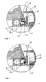
- the washing machine according to FIG. 1 has a substantially cylindrical tub (1) and a rotatably mounted therein, also cylindrical drum (2) for receiving the laundry (not shown).
- the tub (1) is preferably made of alkali-resistant plastic. He has in the center of its bottom (3) has an opening (4), behind which a bearing housing (5) is arranged. It is carried by a bearing cross, not shown, which (not shown) of the tub (1) or directly to the bottom (3) is fixed with its outer ends at the edge of the lateral surface.
- a shaft journal (7) connected to the drum (2) via a flange (6) is passed through the opening (4).
- the bearing for the drum (2) consists of a front and a rear radial ball bearing (8, 9), which are fixed by press fitting in the inner bore (10) of the bearing housing (5) and receive the shaft journal (7).
- the front bearing (8) is protected by a sealing arrangement described below, which is inserted either in the inner bore (10) of the bearing housing (5) or the front opening (4) of the suds container bottom (3).
- Sealing arrangement shown includes a resilient radial shaft seal (11), for example made of NBR, which rests with three dynamically stressed sealing lips (12, 13, 14) on a raceway (15).
- the race (15) is fitted by press fitting on the shaft journal (7).
- the sealing lips (12, 13, 14) are vulcanized to a stiffening ring (19) made of galvanized sheet steel, which has a rectangular profile and thereby a radially directed portion (20) and an axially directed portion (21).
- a circumferential spiral spring (22) on the sealing lip (14) provides better contact with the race (15).
- a pre-shielding which is preceded by the lye side of the radial shaft sealing ring (11).
- This pre-shielding consists of a circumferential ring (24) with a substantially v-shaped, outwardly open cross-section and an edge extension (25) which is formed on the left in the figure, that is, the lye-side rear leg (26).
- the pre-shielding thus formed surrounds the Shaft (7) and protects with its circulating ring (24) the radial shaft sealing ring (11) against a sprinkling with liquor, which is entrained by the rotating drum (2) from the lower portion of the tub (1) in the upper region.
- the union region (28) of the two legs (26, 27) of the pre-shielding therefore extends approximately into the region of the raceway (15).
- the edge projection (25) bears against the edge of the suds container bottom (3) formed by the opening (4) with a seal (29) arranged on its outer peripheral surface.
- the edge is thickened and equipped with an axially directed contact surface (30).
- the seal (29) consists of a thermoplastic elastomer (TPE-O), the remainder of the pre-shielding is made of an alkali-resistant plastic, such as polypropylene.
- the entire pre-shield can be made in a two-component injection molding process.
- the seal (29) forms with respect to the tub base (3) the statically stressed part of the seal assembly.
- the axial region of the stiffening ring (19) on its outer peripheral surface with a vulcanized seal (23) may be provided.
- FIG. 2 shows a sealing arrangement in which instead of a radial shaft sealing ring made of elastic material, a seal (31) made of PTFE is used, which is mounted on a resilient metal ring.
- the pre-shielding is up to the seal (29, s. FIG. 1 a) identical to the one in FIG. 1 illustrated embodiment.
- the seal arrangement in FIG. 4 includes a Vorableung as in the FIGS. 1 and 2 , wherein on the lye-side rear leg (26) a holding web (33) is integrally formed. On this retaining web (33) a radial shaft seal (11) is attached and fixed non-positively with a clamping band (34).
- All four pre-shields described above may have a drainage bore (not shown) which is in the installed state at about the six o'clock position. About this is Liquid which, despite Vorableung has penetrated into the cavity in front of the radial shaft sealing ring (11), returned to the lower region of the tub (1).
- FIGS. 5 and 6 show seal assemblies in which the Vorabminungen have a ring (35) with u-shaped profile. They are also made of alkali-resistant plastic, such as polypropylene. At the lye-side rear leg (36), a fastening pin (37) is integrally formed. Another component of the illustrated sealing arrangements is a stiffening ring (38) which has a rectangular profile. In the radial leg (39) has an opening (40) is arranged, through which the fastening pin (37) extends. As a result, stiffening ring (38) and pre-shielding can be connected to each other, either by welding ( FIG. 5 ) or by latching ( FIG. 6 ). They clamp between them a radial shaft sealing ring (11).
- This radial shaft seal (11) has the from the FIGS. 1 . 3 and 4 known three radial sealing lips (12, 13, 14) as dynamically stressed seals.
- an axially directed portion (42a) of the radial shaft sealing ring (11) is pressed by the axial leg (41) of the stiffening ring (38) to the contact surface at the edge of the tub base (3).
- the bearings can, as in the FIGS. 1a and 3 to 6 shown, between the front bearing (8) and the race (15) one or two disc springs (42) on the shaft journal (7) to be pushed.
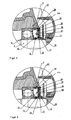
- FIGS. 7 to 9 show storage arrangements of washing machines, in which at least the tub base (3) must be made of a resistant alkali plastic.
- the bearing housing (5) extends beyond the front bearing (8) and thus forms an extension (44) around which the edge (45) of the tub bottom (3) is placed in the region of the opening (4). At least part of the pre-shielding is molded onto this edge (45).
- FIG. 7 shows a variant in which the Vorabcanung consists of a circulating ring (46) with a V-shaped profile and is fully molded onto the edge (45).
- FIG. 1 illustrated radial shaft sealing ring (11), wherein the axial region of the stiffening ring (19) with its vulcanized seal (23) directly on the edge (45) of the tub base (3) is applied.
- the pre-shielding is designed as a U-shaped circular ring.
- the web (47) made of alkali-resistant plastic and molded onto the tub bottom (3), the latter itself forms the lye side rear leg of Vorabprocessung.
- a ring (48) made of stainless steel is clamped on the bridge and has a rectangular profile.
- the lye-side front leg (49) of the pre-shielding is formed.
- a web (50) formed in the area outside the bearing housing (5) to the lye container bottom (3) concentric with the opening a web (50) formed.
- radial shaft seal (11) used.
- FIG. 9 the pre-shielding is identical to the one in FIG. 8 shown arrangement.
Landscapes
- Engineering & Computer Science (AREA)
- General Engineering & Computer Science (AREA)
- Textile Engineering (AREA)
- Mechanical Engineering (AREA)
- Main Body Construction Of Washing Machines And Laundry Dryers (AREA)
- Sealing Of Bearings (AREA)
- Sealing Using Fluids, Sealing Without Contact, And Removal Of Oil (AREA)
- Cleaning By Liquid Or Steam (AREA)
- Centrifugal Separators (AREA)
Description
- Die Erfindung betrifft eine Waschmaschine mit einem im Wesentlichen zylindrischen Laugenbehälter und mit einer darin drehbar gelagerten ebenfalls zylindrischen Trommel, wobei zur drehbaren Lagerung der Trommel an deren Boden ein Wellenzapfen angeordnet ist, welcher sich durch eine Öffnung im Laugenbehälterboden erstreckt und von mindestens zwei Lagern aufgenommen wird, welche innerhalb eines Lagergehäuses angeordnet sind, und wobei zur Abdichtung der Öffnung eine Dichtungsanordnung vorgesehen ist, die mit einem dynamisch beanspruchten Dichtungsteil an dem Wellenzapfen oder einem auf dem Wellenzapfen angeordneten Laufring und mit einem statisch beanspruchten Dichtungsteil am Laugenbehälterboden oder am Lagergehäuse anliegt und laugenseitig vor diesen Dichtungsteilen eine Vorabschirmung besitzt.
- Eine solche Waschmaschine ist aus der
DE 44 22 853 A1 bekannt. - Die zur Lagerung des Wellenzapfens einer Waschmaschinentrommel verwendeten Wälzlager können nur störungsfrei arbeiten und hohe Gebrauchszeiten erreichen, wenn sie durch wirksame Dichtungen während der gesamten Betriebszeit geschützt werden, so dass das Eindringen von Schmutz und das Austreten von Schmierstoff verhindert wird. Bei Trommelwaschmaschinen ist es besonders wichtig, den Eintritt von Kondenswasser und Lauge aus dem Laugenbehälter in das Lager zu verhindern. Hierzu ist es bekannt, vor dem Lager Radialwellendichtringe einzusetzen. Es entstehen jedoch bei zunehmender Alterung und insbesondere bei einem Kontakt der Dichtringe mit Waschlauge Undichtigkeiten, welche das Eindringen von Flüssigkeit in das Lager ermöglichen und dessen Ausfall verursachen. Bei der eingangs beschriebenen Waschmaschine ist deshalb zum Schutz der Dichtringe vor Waschlauge auf dem Wellenzapfen ein erstes, im Wesentlichen kreisringförmiges Schutzelement angeordnet, welches mit einem am Lagergehäuse oder am Laugenbehälterboden angeordneten zweiten Schutzelement eine labyrinthartige Vorabschirmung bildet. Solche Labyrinthdichtungen benötigen immer zwei Bauteile, was ihre Herstellung und ihre Montage verteuert. Bei anderen Ausführungsformen wird ein Teil des Labyrinths durch das elastische Dichtungsmaterial selbst gebildet, wodurch dieses mit Lauge in Kontakt kommt. Dies hat einen schnelleren Verschleiß des nur gering laugenbeständigen Elastomers zur Folge.
- Aus der
DE 101 33 892 A1 ist es bekannt, auf der Laugenbehälterinnenseite einen Führungsflansch anzubringen, der den Wellenzapfen umgibt. Im radialen Abschnitt des Führungsflansches ist eine umlaufende Nut eingeformt, in die der äußere Rand einer am Wellenzapfen angebrachten Schleuderscheibe ragt. Dadurch wird ein labyrinthartiger Spalt geschaffen, der eine Vorabschirmung für den Radialwellendichtring bereitstellt. Bei dieser Anordnung ist es jedoch möglich, dass Spritzwasser an die Laugenbehälterinnenseite gelangt und in Richtung des Wellenzapfens abläuft. Hierbei kann das Wasser aufgrund des Kriechverhaltens durch die Nut zum Radialwellendichtring gelangen, so dass dieser eine gute Dichtwirkung bereitstellen muss. - Aus der
US 2,835,123 ist es bekannt, an der Nabe auf der Laugenbehälterinnenseite eine Vorabschirmung anzubringen, die im Querschnitt einen konischen bzw. zur Trommel hin ansteigenden Verlauf hat und gemeinsam mit einem umlaufenden Steg an der rückseitigen Trommelwand ein Labyrinth bildet. Für diesen Aufbau werden mehrere Einzelteile benötigt. Ferner muss ein großer, axialer Abstand zwischen Laugenbehälterinnenseite und der rückseitigen Trommelwand eingehalten werden, damit die labyrinthartige Vorabschirmung dort angebracht werden kann. - Der Erfindung stellt sich somit das Problem, eine Waschmaschine der eingangs genannten Art dahingehend zu verbessern, dass die elastischen und/oder nur gering laugenbeständigen Dichtungsteile sicher und preiswert vor einem Kontakt mit Waschlauge geschützt werden.
- Erfindungsgemäß wird dieses Problem durch eine Waschmaschine mit den Merkmalen des Patentanspruchs 1 gelöst. Vorteilhafte Ausgestaltungen und Weiterbildungen der Erfindung ergeben sich aus den nachfolgenden Unteransprüchen.
- Durch die Ausstattung einer Waschmaschine mit der erfindungsgemäßen Dichtungsanordnung werden die Kontaktzeiten der Dichtungsteile mit Waschlauge erheblich verringert. Aufgrund ihrer Form wird die in den Bereich der Durchführungsöffnung eintretende Waschlauge sicher und umgehend aus dem Dichtungsbereich in den unteren Bereich des Laugenbehälters abgeführt.
- In der erfindungsgemäßen Ausführungsform erstreckt sich der der Querschnittsöffnung gegenüberliegende Vereinigungsbereich der beiden Schenkel der Vorabschirmung bis annähernd in den Bereich des Wellenzapfens bzw. des Laufrings . Hierdurch werden die Dichtungsteile komplett abgeschirmt.
- In einer weiteren vorteilhaften Ausführungsform fungiert die Vorabschirmung als Träger für wenigstens einen Dichtungsteil (Anspruch 2). Hierdurch kann auf Versteifungsringe aus Metall verzichtet werden, so dass insgesamt eine preiswerte und einfach zu fertigende Dichtungsanordnung realisierbar ist.
- Um festere Anordnungen zu erreichen, kann laugenseitig hinter dem ersten, d.h. dem dynamisch beanspruchten, und zweiten, d.h. dem statisch beanspruchten, Dichtungsteil ein Versteifungsring angeordnet sein (Anspruch 3). Dabei wird in vorteilhafter Weise der Versteifungsring an der Vorabschirmung unter Zwischenlage des ersten und zweiten Dichtungsteils befestigt (Anspruch 4). Auf diese Weise ergibt sich eine sehr stabile, langlebige Anordnung, bei welcher für den Versteifungsring keine weiteren Halterungsmechanismen erforderlich sind.
- Es ist außerdem vorteilhaft, wenn die Vorabschirmung mit einer Abflussbohrung ausgestattet ist welche sich im Einbauzustand etwa in der Sechs-Uhr-Position befindet (Anspruch 5). Durch die Bohrung kann Kondenswasser oder Lauge, welche(s) die Vorabschirmung passiert hat, in den unteren Bereich des Laugenbehälters abfließen.
- Die Vorabschirmung ist erfindungsgemäß wenigstens teilweise aus einem laugenbeständigen Kunststoff hergestellt. Dies führt dazu, dass eine freie Formgestaltung möglich ist. Hierbei ist wenigstens der Teil der Vorabschirmung, der aus dem laugenbeständigen Kunststoff besteht, an den Laugenbehälter angeformt. Hierdurch kann die Vorabschirmung rationell zusammen mit dem Laugenbehälter oder Teilen davon in einem einzigen Spritzgussverfahren hergestellt werden.
- Ausführungsbeispiele der Erfindung sind in den Zeichnungen rein schematisch dargestellt und werden nachfolgend näher beschrieben. Es zeigen:
- Figur 1
- die Lageranordnung einer Waschmaschine in der Seitenansicht im Schnitt;
- Figur 1a, 2 bis 6
- als Ausschnitte einer Dichtungsanordnung als Teil der Lageranordnung.
- Figur 7 bis 9
- als Ausschnitte einer erfindungsgemäßen Waschmaschine.
- In den Figuren sind gleiche oder gleichwirkende Teile durchgängig mit identischen Bezugszeichen versehen.
- Die Waschmaschine gemäß
Figur 1 besitzt einen im Wesentlichen zylindrischen Laugenbehälter (1) und eine darin drehbar gelagerte, ebenfalls zylindrische Trommel (2) zur Aufnahme der Wäsche (nicht dargestellt). Der Laugenbehälter (1) ist vorzugsweise aus laugenbeständigem Kunststoff hergestellt. Er besitzt im Zentrum seines Bodens (3) eine Öffnung (4), hinter der ein Lagergehäuse (5) angeordnet ist. Es wird von einem nicht dargestellten Lagerkreuz getragen, welches mit seinen äußeren Enden am Rand der Mantelfläche (nicht dargestellt) des Laugenbehälters (1) oder direkt am Boden (3) befestigt ist. Ein mit der Trommel (2) über einen Flansch (6) verbundener Wellenzapfen (7) ist durch die Öffnung (4) hindurch geführt. Die Lagerung für die Trommel (2) besteht aus einem vorderen und einem hinteren Radialkugellager (8, 9), die durch Presspassung in der Innenbohrung (10) des Lagergehäuses (5) fixiert sind und den Wellenzapfen (7) aufnehmen. Das vordere Lager (8) wird durch eine nachfolgend beschriebene Dichtungsanordnung geschützt, die entweder in die Innenbohrung (10) des Lagergehäuses (5) oder die davor befindliche Öffnung (4) des Laugenbehälterbodens (3) eingesetzt ist. - Die in
Figur 1a dargestellte Dichtungsanordnung beinhaltet einen elastischen Radialwellendichtring (11), beispielsweise aus NBR, der mit drei dynamisch beanspruchten Dichtlippen (12, 13, 14) an einem Laufring (15) anliegt. Der Laufring (15) ist durch Presspassung auf den Wellenzapfen (7) aufgesetzt. Die Dichtlippen (12, 13, 14) sind an einen Versteifungsring (19) aus verzinktem Stahlblech anvulkanisiert, der ein rechtwinkliges Profil und dadurch einen radial gerichteten Abschnitt (20) und einen axial gerichteten Abschnitt (21) aufweist. Eine umlaufende Spiralfeder (22) an der Dichtlippe (14) sorgt für eine besseren Kontakt mit dem Laufring (15). - Ein weiterer Bestandteil der dargestellten Dichtungsanordnung ist eine Vorabschirmung, die dem Radialwellendichtring (11) laugenseitig vorangestellt ist. Diese Vorabschirmung besteht aus einem Umlaufring (24) mit im Wesentlichen v - förmigem, nach außen geöffnetem Querschnitt und einem Randansatz (25), der an den in der Figur links angeordneten, d. h., den laugenseitig hinteren Schenkel (26) angeformt ist. Die so gebildete Vorabschirmung umgibt den Wellenzapfen (7) und schützt mit ihrem Umlaufring (24) den Radialwellendichtring (11) vor einer Berieselung mit Lauge, welche von der drehenden Trommel (2) aus dem unteren Bereich des Laugenbehälters (1) in den oberen Bereich mitgerissen wird. Der Vereinigungsbereich (28) der beiden Schenkel (26, 27) der Vorabschirmung erstreckt sich deshalb bis annähernd in den Bereich des Laufrings (15). Der Randansatz (25) liegt mit einer auf seiner äußeren Umfangsfläche angeordneten Dichtung (29) an dem durch die Öffnung (4) gebildeten Rand des Laugenbehälterbodens (3) an. Zu diesem Zweck ist der Rand verdickt und mit einer axial gerichteten Anlagefläche (30) ausgestattet. Die Dichtung (29) besteht aus einem thermoplastischen Elastomer (TPE-O), der Rest der Vorabschirmung ist aus einem laugenbeständigen Kunststoff, beispielsweise Polypropylen, gefertigt. Die gesamte Vorabschirmung kann in einem Zweikomponenten-Spritzgussverfahren hergestellt werden. Die Dichtung (29) bildet gegenüber dem Laugenbehälterboden (3) den statisch beanspruchten Teil der Dichtungsanordnung. Um eine flüssigkeitsdichte Anlage des Radialwellendichtrings (11) an der inneren Umfangsfläche des Randansatzes zu erreichen, kann der axiale Bereich des Versteifungsrings (19) auf seiner äußeren Umfangsfläche mit einer anvulkanisierten Dichtung (23) versehen sein.
-
Figur 2 zeigt eine Dichtungsanordnung, bei der anstelle eines Radialwellendichtrings aus elastischem Material eine Dichtung (31) aus PTFE eingesetzt ist, welche auf einem federnden Metallring angebracht ist. Die Vorabschirmung ist bis auf die Dichtung (29, s.Figur 1 a) identisch zu der inFigur 1 dargestellten Ausführungsform. - Bei der in
Figur 3 dargestellten Dichtungsanordnung sind der Randansatz (25) der Vorabschirmung und der äußere Rand (32) des Radialwellendichtrings (11) so geformt, dass der Radialwellendichtring (11) in den Randansatz (25) eingeknüpft werden kann und so durch Formschluss in der Vorabschirmung gehalten wird. Hierdurch entfällt die Notwendigkeit eines Versteifungsrings. In der dargestellten Ausführungsform liegt der Rand (32) des Radialwellendichtrings (11) direkt an der Anlagefläche (30) des Laugenbehälterbodens (3) an und bildet damit den statisch beanspruchten Teil der Dichtungsanordnung. Deswegen kann auf die angespritzte Santoprene-Dichtung verzichtet und die Vorabschirmung vollständig aus Polypropylen gefertigt werden. Den dynamisch beanspruchten Teil der Dichtungsanordnung bilden wie bei der Ausführungsform inFigur 1 drei radial gerichtete Dichtlippen (12, 13, 14). - Die Dichtungsanordnung in
Figur 4 beinhaltet eine Vorabschirmung wie in denFiguren 1 und2 , wobei an dem laugenseitig hinteren Schenkel (26) ein Haltesteg (33) angeformt ist. Auf diesen Haltesteg (33) wird ein Radialwellendichtring (11) aufgesteckt und mit einem Spannband (34) kraftschlüssig fixiert. - Alle vier vorbeschriebenen Vorabschirmungen können eine Abflussbohrung (nicht dargestellt) besitzen, welche sich im Einbauzustand etwa in der Sechs-Uhr-Position befindet. Hierüber wird Flüssigkeit, die trotz Vorabschirmung in den Hohlraum vor dem Radialwellendichtring (11) eingedrungen ist, in den unteren Bereich des Laugenbehälters (1) zurückgeleitet.
- Die
Figuren 5 und 6 zeigen Dichtungsanordnungen, bei denen die Vorabschirmungen einen Ring (35) mit u-förmigem Profil besitzen. Sie sind ebenfalls aus laugenfestem Kunststoff, beispielsweise Polypropylen, hergestellt. An den laugenseitig hinteren Schenkel (36) ist ein Befestigungszapfen (37) angeformt. Weiteres Bestandteil der dargestellten Dichtungsanordnungen ist ein Versteifungsring (38), der ein rechtwinkliges Profil besitzt. In dem radialen Schenkel (39) ist eine Öffnung (40) angeordnet, durch die sich der Befestigungszapfen (37) erstreckt. Hierdurch können Versteifungsring (38) und Vorabschirmung miteinander verbunden werden, entweder durch Verschweißen (Figur 5 ) oder durch Verrasten (Figur 6 ). Dabei klemmen sie zwischen sich einen Radialwellendichtring (11) ein. Dieser Radialwellendichtring (11) besitzt die aus denFiguren 1 ,3 und 4 bekannten drei radialen Dichtlippen (12, 13, 14) als dynamisch beanspruchte Dichtungen. Als statische Dichtung wird durch den axialen Schenkel (41) des Versteifungsrings (38) ein ebenfalls axial gerichteter Abschnitt (42a) des Radialwellendichtrings (11) an die Anlagefläche am Rand des Laugenbehälterbodens (3) gedrückt. - Zur Spannung der Lager kann, wie in den
Figuren 1a und3 bis 6 dargestellt, zwischen dem vorderen Lager (8) und dem Laufring (15) eine oder zwei Tellerfedern (42) auf den Wellenzapfen (7) aufgeschoben sein. - Die
Figuren 7 bis 9 zeigen Lageranordnungen von Waschmaschinen, bei denen wenigstens der Laugenbehälterboden (3) zwingend aus einem laugenbeständigen Kunststoff hergestellt sein muss. Bei diesen Lageranordnungen erstreckt sich das Lagergehäuse (5) über das vordere Lager (8) hinaus und bildet so einen Fortsatz (44), um den der Rand (45) des Laugenbehälterbodens (3) im Bereich der Öffnung (4) herumgelegt ist. An diesen Rand (45) ist wenigstens ein Teil der Vorabschirmung angespritzt. -
Figur 7 zeigt eine Variante, bei der die Vorabschirmung aus einem Umlaufring (46) mit v-förmigem Profil besteht und vollständig an den Rand (45) angespritzt ist. Als Dichtung fungiert der inFigur 1 dargestellte Radialwellendichtring (11), wobei der axiale Bereich des Versteifungsrings (19) mit seiner anvulkanisierten Dichtung (23) direkt am Rand (45) des Laugenbehälterbodens (3) anliegt. - Bei der in
Figur 8 gezeigten Dichtungsanordnung ist die Vorabschirmung als u-förmiger Umlaufring ausgebildet. Hier ist nur der Steg (47) aus laugenbeständigem Kunststoff gefertigt und an den Laugenbehälterboden (3) angespritzt, wobei letzterer selbst den laugenseitig hinteren Schenkel der Vorabschirmung bildet. Zur Komplettierung ist auf den Steg ein Ring (48) aus Edelstahl geklemmt, der ein rechtwinkliges Profil besitzt. Hierdurch wird der laugenseitig vordere Schenkel (49) der Vorabschirmung gebildet. Im Bereich außerhalb des Lagergehäuses (5) ist an den Laugenbehälterboden (3) konzentrisch zur Öffnung ein Steg (50) angeformt. Dieser bildet mit einem aufgesteckten Ring (51) mit abgewinkeltem Profil eine zweite Vorabschirmung. Als Dichtung wird der aus denFiguren 1 und7 bekannte Radialwellendichtring (11) verwendet. - In
Figur 9 ist die Vorabschirmung identisch zu der inFigur 8 gezeigten Anordnung. Hier wird aber anstelle des Radialwellendichtrings die ausFigur 2 bekannte Dichtung (31) aus PTFE verwendet.
Claims (5)
- Waschmaschine mit einem im Wesentlichen zylindrischen Laugenbehälter (1) und mit einer darin drehbar gelagerten ebenfalls zylindrischen Trommel (2), wobei zur drehbaren Lagerung der Trommel (2) an deren Boden ein Wellenzapfen (7) angeordnet ist, welcher sich durch eine Öffnung (4) im Laugenbehälterboden (3) erstreckt und von mindestens zwei Lagern (8, 9) aufgenommen wird, welche innerhalb eines Lagergehäuses (5) angeordnet sind, und wobei zur Abdichtung der Öffnung (4) eine Dichtungsanordnung vorgesehen ist, die mit einem dynamisch beanspruchten Dichtungsteil (12, 13, 14) an dem Wellenzapfen (7) oder einem auf dem Wellenzapfen (7) angeordneten Laufring (15) und mit einem statisch beanspruchten Dichtungsteil (23, 29) am Laugenbehälterboden (3) oder am Lagergehäuse (5) anliegt und laugenseitig vor diesen Dichtungsteilen eine Vorabschirmung besitzt,
dadurch gekennzeichnet,
dass die Vorabschirmung als ein den Wellenzapfen (7) umgebender Umlaufring (24, 46) mit im Wesentlichen v- oder u-förmigem, nach außen geöffnetem Querschnitt ausgebildet ist, so dass sich der der Querschnittsöffnung gegenüberliegende Vereinigungsbereich von zwei das U oder V bildenen Schenkeln (26, 27) der Vorabschirmung bis annähernd in den Bereich des Wellenzapfens (7) bzw. des Laufrings (15) erstreckt, wobei wenigstens ein Teil der Vorabschirmung aus einem laugenbeständigen Kunststoff hergestellt und wenigstens dieser Teil der Vorabschirmung an den Laugenbehälterboden (3), welcher aus einem Laugenbeständigen Kunststoff hergestellt ist, angeformt ist. - Waschmaschine mit einer Dichtungsanordnung nach Anspruch 1,
dadurch gekennzeichnet,
dass die Vorabschirmung als Träger für wenigstens einen Dichtungsteil fungiert. - Waschmaschine mit einer Dichtungsanordnung nach mindestens einem der Ansprüche 1 bis 2,
dadurch gekennzeichnet,
dass laugenseitig hinter dem dynamisch beanspruchten Dichtungsteil (12, 13, 14) und dem statisch beanspruchten Dichtungsteil (23, 29) ein Versteifungsring (38) angeordnet ist. - Waschmaschine mit einer Dichtungsanordnung nach Anspruch 3,
dadurch gekennzeichnet,
dass der Versteifungsring (38) an der Vorabschirmung unter Zwischenlage des dynamisch beanspruchten Dichtungsteils (12, 13, 14) und des statisch beanspruchten Dichtungsteils (23, 29) befestigt ist. - Waschmaschine mit einer Dichtungsanordnung nach mindestens einem der Ansprüche 1 bis 4,
dadurch gekennzeichnet
dass die Vorabschirmung mit einer Abflussbohrung ausgestattet ist welche sich im Einbauzustand etwa in der Sechs-Uhr-Position befindet.
Applications Claiming Priority (2)
| Application Number | Priority Date | Filing Date | Title |
|---|---|---|---|
| DE10342262A DE10342262B3 (de) | 2003-09-11 | 2003-09-11 | Waschmaschine mit einer Dichtungsanordnung |
| DE10342262 | 2003-09-11 |
Publications (3)
| Publication Number | Publication Date |
|---|---|
| EP1514965A2 EP1514965A2 (de) | 2005-03-16 |
| EP1514965A3 EP1514965A3 (de) | 2007-10-10 |
| EP1514965B1 true EP1514965B1 (de) | 2010-10-27 |
Family
ID=33305260
Family Applications (1)
| Application Number | Title | Priority Date | Filing Date |
|---|---|---|---|
| EP04018996A Expired - Lifetime EP1514965B1 (de) | 2003-09-11 | 2004-08-11 | Waschmaschine mit einer Dichtungsanordnung |
Country Status (4)
| Country | Link |
|---|---|
| EP (1) | EP1514965B1 (de) |
| AT (1) | ATE486164T1 (de) |
| DE (2) | DE10342262B3 (de) |
| ES (1) | ES2351584T3 (de) |
Families Citing this family (8)
| Publication number | Priority date | Publication date | Assignee | Title |
|---|---|---|---|---|
| DE10342254B3 (de) * | 2003-09-11 | 2004-11-18 | Miele & Cie. Kg | Waschmaschine mit einer Dichtungsanordnung |
| DE102005062891B3 (de) * | 2005-12-29 | 2007-08-30 | Ab Skf | Lageranordnung |
| WO2007126170A2 (en) | 2006-05-02 | 2007-11-08 | Lg Electronics Inc. | Drum washing machine |
| EP2708630B1 (de) | 2012-09-14 | 2019-04-24 | Samsung Electronics Co., Ltd. | Trommelwaschmaschine |
| DE102014206634A1 (de) * | 2014-04-07 | 2015-10-08 | BSH Hausgeräte GmbH | Lageranordnung und Waschmaschine mit einer Lageranordnung |
| DE102018202762A1 (de) * | 2018-02-23 | 2019-08-29 | BSH Hausgeräte GmbH | Waschmaschine mit einer Dichtanordnung für eine Lageranordnung eines Laugenbehälters der Waschmaschine |
| CN110791922A (zh) * | 2018-08-01 | 2020-02-14 | 青岛海尔滚筒洗衣机有限公司 | 一种外筒及滚筒洗衣机 |
| CN109652949B (zh) * | 2018-12-06 | 2020-10-23 | 无锡小天鹅电器有限公司 | 衣物处理装置 |
Family Cites Families (5)
| Publication number | Priority date | Publication date | Assignee | Title |
|---|---|---|---|---|
| US2835123A (en) * | 1954-06-28 | 1958-05-20 | Galinski Roman | Washing apparatus with liquid seal for rotating shaft |
| DE3838824C2 (de) * | 1988-11-17 | 1995-06-08 | Kugelfischer G Schaefer & Co | Dichtung, bestehend aus mehreren Dichtringen |
| ATE147803T1 (de) * | 1992-07-20 | 1997-02-15 | Waschgeraete Gmbh I L | Trommelwaschmaschine mit einem laugenbehälter aus kunststoff |
| DE4422853C2 (de) * | 1994-06-30 | 2003-06-12 | Miele & Cie | Lagerabdichtung für Radial-Wälzlager |
| DE10133892A1 (de) * | 2001-07-12 | 2003-01-30 | Miele & Cie | Dichtungssystem zur Abdichtung von zwei relativ zueinander verdrehbaren Maschinenelementen |
-
2003
- 2003-09-11 DE DE10342262A patent/DE10342262B3/de not_active Expired - Fee Related
-
2004
- 2004-08-11 DE DE502004011817T patent/DE502004011817D1/de not_active Expired - Lifetime
- 2004-08-11 ES ES04018996T patent/ES2351584T3/es not_active Expired - Lifetime
- 2004-08-11 AT AT04018996T patent/ATE486164T1/de active
- 2004-08-11 EP EP04018996A patent/EP1514965B1/de not_active Expired - Lifetime
Also Published As
| Publication number | Publication date |
|---|---|
| EP1514965A3 (de) | 2007-10-10 |
| EP1514965A2 (de) | 2005-03-16 |
| ES2351584T3 (es) | 2011-02-08 |
| DE10342262B3 (de) | 2004-11-18 |
| ATE486164T1 (de) | 2010-11-15 |
| DE502004011817D1 (de) | 2010-12-09 |
Similar Documents
| Publication | Publication Date | Title |
|---|---|---|
| EP1514966B1 (de) | Waschmaschine mit einer Dichtungsanordnung | |
| DE69800162T2 (de) | Dichtung für Wälzlager | |
| DE102013218635B4 (de) | Dichtungsanordnung für Radlager mit vorgespanntem Schleuderblech | |
| DE3148530C2 (de) | ||
| DE69608003T2 (de) | Lager | |
| DE69004080T2 (de) | Kassettendichtung und ihr herstellungsverfahren. | |
| EP0609659B1 (de) | Planetenträger-Anordnung mit einer ringförmigen Ölstauscheibe | |
| DE2835971A1 (de) | Rad- und lageranordnung | |
| WO2004065806A1 (de) | Dichtungsbaugruppe für eine lagerbüchse | |
| DE3412484A1 (de) | Oeldichtungsanordnung | |
| EP2899307B1 (de) | Waschaggregat für eine Waschmaschine | |
| WO2019114853A1 (de) | Dichtungsanordnung eines radlagers | |
| EP1514965B1 (de) | Waschmaschine mit einer Dichtungsanordnung | |
| DE3207488C2 (de) | ||
| DE102020112044A1 (de) | Wälzlager mit Schleuderscheibe | |
| DE4422853A1 (de) | Lagerabdichtung für Radial-Wälzlager | |
| DE3616999A1 (de) | Dichtung, insbesondere fuer waelzlager | |
| DE69418281T2 (de) | Lagereinheit mit interner Dichtung | |
| DE102008006656A1 (de) | Kupplungsausrücklagereinrichtung | |
| WO2002044578A1 (de) | Abdichtung für ein ausrücklager | |
| DE602005003239T2 (de) | Mehrstufige Öldichtung für einen Werkzeugmaschinenantrieb | |
| DE4408831A1 (de) | Abdichtung für Gelenkkreuzbüchsen | |
| DE8632410U1 (de) | Dichtungsgarnitur, insbesondere für Eisenbahnachsenlager | |
| DE10140837C1 (de) | Dichtungsanordnung | |
| DE102022130974B4 (de) | Vordichtungselement mit einer Rotationsachse für eine dynamische Wellendichtungsanordnung, eine Wellendichtungsanordnung mit einer Rotationsachse für eine dynamische Dichtung, sowie eine Wellenbaugruppe |
Legal Events
| Date | Code | Title | Description |
|---|---|---|---|
| PUAI | Public reference made under article 153(3) epc to a published international application that has entered the european phase |
Free format text: ORIGINAL CODE: 0009012 |
|
| AK | Designated contracting states |
Kind code of ref document: A2 Designated state(s): AT BE BG CH CY CZ DE DK EE ES FI FR GB GR HU IE IT LI LU MC NL PL PT RO SE SI SK TR |
|
| AX | Request for extension of the european patent |
Extension state: AL HR LT LV MK |
|
| PUAL | Search report despatched |
Free format text: ORIGINAL CODE: 0009013 |
|
| AK | Designated contracting states |
Kind code of ref document: A3 Designated state(s): AT BE BG CH CY CZ DE DK EE ES FI FR GB GR HU IE IT LI LU MC NL PL PT RO SE SI SK TR |
|
| AX | Request for extension of the european patent |
Extension state: AL HR LT LV MK |
|
| 17P | Request for examination filed |
Effective date: 20071025 |
|
| AKX | Designation fees paid |
Designated state(s): AT BE BG CH CY CZ DE DK EE ES FI FR GB GR HU IE IT LI LU MC NL PL PT RO SE SI SK TR |
|
| 17Q | First examination report despatched |
Effective date: 20090806 |
|
| GRAP | Despatch of communication of intention to grant a patent |
Free format text: ORIGINAL CODE: EPIDOSNIGR1 |
|
| GRAS | Grant fee paid |
Free format text: ORIGINAL CODE: EPIDOSNIGR3 |
|
| GRAA | (expected) grant |
Free format text: ORIGINAL CODE: 0009210 |
|
| AK | Designated contracting states |
Kind code of ref document: B1 Designated state(s): AT BE BG CH CY CZ DE DK EE ES FI FR GB GR HU IE IT LI LU MC NL PL PT RO SE SI SK TR |
|
| REG | Reference to a national code |
Ref country code: GB Ref legal event code: FG4D Free format text: NOT ENGLISH |
|
| REG | Reference to a national code |
Ref country code: CH Ref legal event code: EP |
|
| REG | Reference to a national code |
Ref country code: IE Ref legal event code: FG4D Free format text: LANGUAGE OF EP DOCUMENT: GERMAN Ref country code: GB Ref legal event code: 746 Effective date: 20101102 |
|
| REF | Corresponds to: |
Ref document number: 502004011817 Country of ref document: DE Date of ref document: 20101209 Kind code of ref document: P |
|
| REG | Reference to a national code |
Ref country code: ES Ref legal event code: FG2A Effective date: 20110127 |
|
| REG | Reference to a national code |
Ref country code: NL Ref legal event code: VDEP Effective date: 20101027 |
|
| REG | Reference to a national code |
Ref country code: IE Ref legal event code: FD4D |
|
| PG25 | Lapsed in a contracting state [announced via postgrant information from national office to epo] |
Ref country code: PT Free format text: LAPSE BECAUSE OF FAILURE TO SUBMIT A TRANSLATION OF THE DESCRIPTION OR TO PAY THE FEE WITHIN THE PRESCRIBED TIME-LIMIT Effective date: 20110228 Ref country code: FI Free format text: LAPSE BECAUSE OF FAILURE TO SUBMIT A TRANSLATION OF THE DESCRIPTION OR TO PAY THE FEE WITHIN THE PRESCRIBED TIME-LIMIT Effective date: 20101027 Ref country code: NL Free format text: LAPSE BECAUSE OF FAILURE TO SUBMIT A TRANSLATION OF THE DESCRIPTION OR TO PAY THE FEE WITHIN THE PRESCRIBED TIME-LIMIT Effective date: 20101027 Ref country code: SI Free format text: LAPSE BECAUSE OF FAILURE TO SUBMIT A TRANSLATION OF THE DESCRIPTION OR TO PAY THE FEE WITHIN THE PRESCRIBED TIME-LIMIT Effective date: 20101027 Ref country code: SE Free format text: LAPSE BECAUSE OF FAILURE TO SUBMIT A TRANSLATION OF THE DESCRIPTION OR TO PAY THE FEE WITHIN THE PRESCRIBED TIME-LIMIT Effective date: 20101027 Ref country code: BG Free format text: LAPSE BECAUSE OF FAILURE TO SUBMIT A TRANSLATION OF THE DESCRIPTION OR TO PAY THE FEE WITHIN THE PRESCRIBED TIME-LIMIT Effective date: 20110127 |
|
| PG25 | Lapsed in a contracting state [announced via postgrant information from national office to epo] |
Ref country code: GR Free format text: LAPSE BECAUSE OF FAILURE TO SUBMIT A TRANSLATION OF THE DESCRIPTION OR TO PAY THE FEE WITHIN THE PRESCRIBED TIME-LIMIT Effective date: 20110128 |
|
| PG25 | Lapsed in a contracting state [announced via postgrant information from national office to epo] |
Ref country code: CZ Free format text: LAPSE BECAUSE OF FAILURE TO SUBMIT A TRANSLATION OF THE DESCRIPTION OR TO PAY THE FEE WITHIN THE PRESCRIBED TIME-LIMIT Effective date: 20101027 Ref country code: EE Free format text: LAPSE BECAUSE OF FAILURE TO SUBMIT A TRANSLATION OF THE DESCRIPTION OR TO PAY THE FEE WITHIN THE PRESCRIBED TIME-LIMIT Effective date: 20101027 Ref country code: IE Free format text: LAPSE BECAUSE OF FAILURE TO SUBMIT A TRANSLATION OF THE DESCRIPTION OR TO PAY THE FEE WITHIN THE PRESCRIBED TIME-LIMIT Effective date: 20101027 |
|
| PG25 | Lapsed in a contracting state [announced via postgrant information from national office to epo] |
Ref country code: RO Free format text: LAPSE BECAUSE OF FAILURE TO SUBMIT A TRANSLATION OF THE DESCRIPTION OR TO PAY THE FEE WITHIN THE PRESCRIBED TIME-LIMIT Effective date: 20101027 Ref country code: DK Free format text: LAPSE BECAUSE OF FAILURE TO SUBMIT A TRANSLATION OF THE DESCRIPTION OR TO PAY THE FEE WITHIN THE PRESCRIBED TIME-LIMIT Effective date: 20101027 Ref country code: SK Free format text: LAPSE BECAUSE OF FAILURE TO SUBMIT A TRANSLATION OF THE DESCRIPTION OR TO PAY THE FEE WITHIN THE PRESCRIBED TIME-LIMIT Effective date: 20101027 Ref country code: PL Free format text: LAPSE BECAUSE OF FAILURE TO SUBMIT A TRANSLATION OF THE DESCRIPTION OR TO PAY THE FEE WITHIN THE PRESCRIBED TIME-LIMIT Effective date: 20101027 |
|
| PLBE | No opposition filed within time limit |
Free format text: ORIGINAL CODE: 0009261 |
|
| STAA | Information on the status of an ep patent application or granted ep patent |
Free format text: STATUS: NO OPPOSITION FILED WITHIN TIME LIMIT |
|
| 26N | No opposition filed |
Effective date: 20110728 |
|
| REG | Reference to a national code |
Ref country code: ES Ref legal event code: GC2A Effective date: 20110926 |
|
| REG | Reference to a national code |
Ref country code: DE Ref legal event code: R097 Ref document number: 502004011817 Country of ref document: DE Effective date: 20110728 |
|
| BERE | Be: lapsed |
Owner name: MIELE & CIE. K.G. Effective date: 20110831 |
|
| PG25 | Lapsed in a contracting state [announced via postgrant information from national office to epo] |
Ref country code: MC Free format text: LAPSE BECAUSE OF NON-PAYMENT OF DUE FEES Effective date: 20110831 |
|
| REG | Reference to a national code |
Ref country code: CH Ref legal event code: PL |
|
| PG25 | Lapsed in a contracting state [announced via postgrant information from national office to epo] |
Ref country code: CH Free format text: LAPSE BECAUSE OF NON-PAYMENT OF DUE FEES Effective date: 20110831 Ref country code: LI Free format text: LAPSE BECAUSE OF NON-PAYMENT OF DUE FEES Effective date: 20110831 |
|
| PG25 | Lapsed in a contracting state [announced via postgrant information from national office to epo] |
Ref country code: BE Free format text: LAPSE BECAUSE OF NON-PAYMENT OF DUE FEES Effective date: 20110831 |
|
| REG | Reference to a national code |
Ref country code: AT Ref legal event code: MM01 Ref document number: 486164 Country of ref document: AT Kind code of ref document: T Effective date: 20110811 |
|
| PG25 | Lapsed in a contracting state [announced via postgrant information from national office to epo] |
Ref country code: AT Free format text: LAPSE BECAUSE OF NON-PAYMENT OF DUE FEES Effective date: 20110811 |
|
| PG25 | Lapsed in a contracting state [announced via postgrant information from national office to epo] |
Ref country code: CY Free format text: LAPSE BECAUSE OF EXPIRATION OF PROTECTION Effective date: 20101027 Ref country code: LU Free format text: LAPSE BECAUSE OF NON-PAYMENT OF DUE FEES Effective date: 20110811 |
|
| PG25 | Lapsed in a contracting state [announced via postgrant information from national office to epo] |
Ref country code: TR Free format text: LAPSE BECAUSE OF FAILURE TO SUBMIT A TRANSLATION OF THE DESCRIPTION OR TO PAY THE FEE WITHIN THE PRESCRIBED TIME-LIMIT Effective date: 20101027 |
|
| PG25 | Lapsed in a contracting state [announced via postgrant information from national office to epo] |
Ref country code: HU Free format text: LAPSE BECAUSE OF FAILURE TO SUBMIT A TRANSLATION OF THE DESCRIPTION OR TO PAY THE FEE WITHIN THE PRESCRIBED TIME-LIMIT Effective date: 20101027 |
|
| REG | Reference to a national code |
Ref country code: FR Ref legal event code: PLFP Year of fee payment: 13 |
|
| REG | Reference to a national code |
Ref country code: FR Ref legal event code: PLFP Year of fee payment: 14 |
|
| REG | Reference to a national code |
Ref country code: FR Ref legal event code: PLFP Year of fee payment: 15 |
|
| PGFP | Annual fee paid to national office [announced via postgrant information from national office to epo] |
Ref country code: IT Payment date: 20220819 Year of fee payment: 19 Ref country code: GB Payment date: 20220823 Year of fee payment: 19 Ref country code: ES Payment date: 20220908 Year of fee payment: 19 Ref country code: DE Payment date: 20220831 Year of fee payment: 19 |
|
| PGFP | Annual fee paid to national office [announced via postgrant information from national office to epo] |
Ref country code: FR Payment date: 20220824 Year of fee payment: 19 |
|
| P01 | Opt-out of the competence of the unified patent court (upc) registered |
Effective date: 20230529 |
|
| REG | Reference to a national code |
Ref country code: DE Ref legal event code: R119 Ref document number: 502004011817 Country of ref document: DE |
|
| GBPC | Gb: european patent ceased through non-payment of renewal fee |
Effective date: 20230811 |
|
| PG25 | Lapsed in a contracting state [announced via postgrant information from national office to epo] |
Ref country code: GB Free format text: LAPSE BECAUSE OF NON-PAYMENT OF DUE FEES Effective date: 20230811 |
|
| PG25 | Lapsed in a contracting state [announced via postgrant information from national office to epo] |
Ref country code: IT Free format text: LAPSE BECAUSE OF NON-PAYMENT OF DUE FEES Effective date: 20230811 Ref country code: GB Free format text: LAPSE BECAUSE OF NON-PAYMENT OF DUE FEES Effective date: 20230811 Ref country code: FR Free format text: LAPSE BECAUSE OF NON-PAYMENT OF DUE FEES Effective date: 20230831 Ref country code: DE Free format text: LAPSE BECAUSE OF NON-PAYMENT OF DUE FEES Effective date: 20240301 |
|
| REG | Reference to a national code |
Ref country code: ES Ref legal event code: FD2A Effective date: 20240927 |
|
| PG25 | Lapsed in a contracting state [announced via postgrant information from national office to epo] |
Ref country code: ES Free format text: LAPSE BECAUSE OF NON-PAYMENT OF DUE FEES Effective date: 20230812 |
|
| PG25 | Lapsed in a contracting state [announced via postgrant information from national office to epo] |
Ref country code: ES Free format text: LAPSE BECAUSE OF NON-PAYMENT OF DUE FEES Effective date: 20230812 |