EP1514818A2 - Wickelvorrichtung - Google Patents
Wickelvorrichtung Download PDFInfo
- Publication number
- EP1514818A2 EP1514818A2 EP04104294A EP04104294A EP1514818A2 EP 1514818 A2 EP1514818 A2 EP 1514818A2 EP 04104294 A EP04104294 A EP 04104294A EP 04104294 A EP04104294 A EP 04104294A EP 1514818 A2 EP1514818 A2 EP 1514818A2
- Authority
- EP
- European Patent Office
- Prior art keywords
- pawl
- winding
- damping element
- wound
- force
- Prior art date
- Legal status (The legal status is an assumption and is not a legal conclusion. Google has not performed a legal analysis and makes no representation as to the accuracy of the status listed.)
- Withdrawn
Links
Images

Classifications
-
- B—PERFORMING OPERATIONS; TRANSPORTING
- B65—CONVEYING; PACKING; STORING; HANDLING THIN OR FILAMENTARY MATERIAL
- B65H—HANDLING THIN OR FILAMENTARY MATERIAL, e.g. SHEETS, WEBS, CABLES
- B65H18/00—Winding webs
- B65H18/08—Web-winding mechanisms
- B65H18/26—Mechanisms for controlling contact pressure on winding-web package, e.g. for regulating the quantity of air between web layers
Definitions
- the invention relates to a device for winding a material web, in particular paper or board web, on a spool, wherein the web is guided over a carrier drum or the like, between the Tambour and the carrying drum a winding nip is formed and the Tambour for generating a line force in the winding nip in a primary winding phase via a primary pressing system and in a secondary winding phase via a secondary pressing system can be pressed against the carrier drum.
- a comparable one Winder is, for example, in DE 35 39 980 C2 and US Pat. No. 3,614,011.
- rewinding devices there are presently known as machine reels, in both the primary and the secondary winding area each with a Pressure system (e.g., Pope Roller, MasterReel, OptiReel, etc.), or according to the so-called Sirius principle working machine scooter with only one pressing system.
- a Pressure system e.g., Pope Roller, MasterReel, OptiReel, etc.
- Sirius principle working machine scooter with only one pressing system.
- the invention is based on the object, an improved winding device of the type mentioned above, in which the aforementioned Problems are eliminated.
- it should be ensured that during the transfer of the wound spool from the primary to the secondary winding area no harmful pressure peaks arise.
- a device for Winding a web, in particular paper or board web, on a spool wherein the web over a carrier drum or the like is guided, between the spool and the carrier drum a winding nip is formed and the drum for generating a line force in the winding nip in a primary winding phase via a primary press system and in one Secondary winding phase via a secondary press system to the carrier drum is pressable, and wherein the secondary pressing system and the wound Tambour via at least one damping element with each other can be brought.
- the damping element can bring when engaged with each other of the secondary pressing system and the wound spool generates increase the contact pressure at least over a portion of the rising Power are attenuated away.
- the damping element is preferably only in a final phase of mutual approach of the secondary press system and the coiled Tambours effective.
- About the damping element can, for example, up to a predetermined Force level can be generated a steady increase in contact pressure.
- the damping element is preferably associated with the secondary press system.
- At least one mechanical, at least one electromechanical, at least one pneumatic and / or at least one hydraulic Be provided damping element For example, at least one mechanical, at least one electromechanical, at least one pneumatic and / or at least one hydraulic Be provided damping element.
- a control device For controlling and / or regulating the pressure or line force is at least a control device is provided. It can the primary press system and the secondary pressing system be associated with a control device, wherein the primary press system and the secondary press system preferably a common control device is assigned.
- At least a hydraulic control device may be provided.
- Device is the wound in the primary winding area tambour to further Wrapping preferably according to the principle of a so-called Pope Rollers zugerondetes to a Sekundärwickel Symposium, preferably with Runner provided secondary transport system transferable.
- the secondary pressing system may, for example, comprise at least one carriage, comprise at least one lever and / or the like.
- Device is the secondary pressing system associated secondary lever provided with a pawl, wherein the wound tambour on the latch with the secondary lever engages and the damping element between the secondary lever and the pawl is provided.
- the latch is relative to the secondary lever in particular over a predeterminable area pivotable.
- the pawl may be provided with a pressure roller, wherein the wound Tambour comes into contact with this pressure roller.
- the secondary lever can be pivoted to the wound drum, as soon as this to the preferably provided with rails secondary transport system was handed over.
- the secondary lever is initially only up to a predefinable Position swiveled to the wound spool, in the still no non-positive contact of the pawl or the pressure roller for through more wrapping growing drumming prevails. It is in particular Such an embodiment conceivable in which the secondary lever initially only until is pivotable to a fixed stop.
- the secondary lever can via at least one particular hydraulic Actuator be acted upon.
- a means for measuring the wound by the Tambour force applied via the pawl to the secondary lever intended for example, in the field of Be provided pressure roller.
- Device is the secondary lever on the particular hydraulic actuator acted upon with relatively little force until by compression of the damping element through the wound tambour on the Pawl on the secondary lever applied force slowly rises.
- the latch can after a transfer of the wound spool to the Sekundärwickel Scheme to cancel the damping effect or for Definition of a fixed reference point for coupling in a possible Secondary drive with respect to the secondary lever be fixable.
- the damping element may in particular an elastic element or the like.
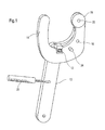
- Figure 1 shows a schematic representation of a secondary lever 10, the a secondary pressing system of a device for winding a Material web, in particular paper or board web, on a spool belongs.
- the damping element 12 is between the secondary lever 10 and a pivotally mounted on this Pawl 14 is provided.
- the wound tambour passes over the latch 14 associated with the secondary press system of the winding device Secondary lever 10 in engagement.
- the pawl 14 is about the axis 16 relative to the secondary lever 10 via a predeterminable range swiveling.
- the damping element 12 can now when engaged with each other bring the secondary press system or the secondary lever 10 and the wound drum produced at least about increase in contact pressure to attenuate a portion of the increasing force curve.
- the damping element 12 as it is in particular also from the Figures 2 to 5 results, only in a final phase of the mutual approach of the secondary press system and the wound spool.
- About the damping element 12 is then up to a predetermined level of force a steady increase in contact pressure can be generated.
- the damping element 12 is in present case associated with the secondary pressing system, i. at the present Embodiment between the secondary lever 10 and the pivotally provided on this mounted pawl 14.
- the damping element 12 may be, for example, a mechanical, an electromechanical, a pneumatic or a hydraulic Damping act. Basically, several such Damping elements 12 may be provided.
- the wound in the Primärwickel Symposium Tambour is for further winding preferably on the principle of a so-called Pope Rollers on a associated with the secondary winding area, preferably with rails provided secondary transport system transferable.
- the secondary lever 10 can be pivoted, for example, to the wound drum, as soon as this to the preferably provided with rails secondary transport system was handed over.
- the secondary lever 10 is expediently initially only up to one predeterminable position on the wound spool swung in the no force-locking contact of the pawl 14 or the pressure roller 18 to the growing through the further winding Tambour prevails. So are in particular, such embodiments conceivable in which the secondary lever 10th initially only up to a fixed stop is pivotable.
- the secondary lever 10 is connected via at least one e.g. hydraulic actuator 20 acted upon.
- this measuring device 22 provided in the region of the pressure roller 18. It includes, for example a measuring pin 22, via which the pressure roller 18 rotatably on the pawl 14th is stored.
- the secondary lever 10 can now, for example, with a hydraulic Actuator 20 are acted upon with relatively little force until by compression of the damping element 12 by the wound Tambour over the pawl 14 on the secondary lever 10 force applied slowly increases.
- the pawl 14 can then after a transfer of the wound spool to the secondary winding area to cancel the damping effect or establishing a fixed reference point for engaging a possible Secondary drive with respect to the secondary lever 10 can be fixed. there can the pawl 14, for example via a pin 24 with respect to the secondary lever 10 are locked.
- the damping element 12 may in particular comprise an elastic element.
- Figures 2 to 5 show the movement of the pawl 14 relative to Secondary lever 10 when latching.
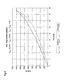
- FIG. 6 shows an exemplary static force / displacement characteristic curve
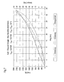
- FIG. 7 an exemplary dynamic force / displacement and energy / displacement characteristics of Damping element 12.
- damping element 12 which is for example a mechanical, electromechanical or pneumatic damping element can act in the area of secondary pressure, the increase in force over the last stretch of approach of the pressing system (lever, Carriage or the like) are continuously led to the desired level.
- a hydraulic control in the primary and secondary winding area can track slow setpoint changes much more precisely.
- the secondary lever 10 to the wound drum be swung. This conveniently takes up to one fixed stop, in which no force-locking contact of the pressure roller 18 to the growing drumming prevails.
- the steady winding increase provides now that the pivotally mounted about the axis 16 pawl 14 slowly is pushed back and the pawl 14 increasingly clasped the Tamillianlocke.
- the example hydraulic actuator 20 and the concerned hydraulic can in this phase with low pressure in one "Waiting position" persist until through the compression of the example formed by an elastic element damping element 12, the force measured in the measuring pin 22 on the pressure roller 18, slowly rises.
Landscapes
- Winding Of Webs (AREA)
- Replacement Of Web Rolls (AREA)
Abstract
Description
- Figur 1
- eine schematische Darstellung eines mit einer Klinke und einem Dämpfungselement versehenen Sekundärhebels,
- Figuren 2 bis 5
- den Bewegungsablauf der Klinke relativ zum Sekundärhebel beim Einklinken,
- Figur 6
- eine beispielhafte statische Kraft/Weg-Kennlinie für das Dämpfungselement und
- Figur 7
- eine beispielhafte dynamische Kraft/Weg- und Energie/Weg-Kennlinie für das Dämpfungselement.
- 10
- Sekundärhebel
- 12
- Dämpfungselement
- 14
- Klinke
- 16
- Schwenkachse
- 18
- Anpressrolle
- 20
- Betätigungselement
- 22
- Messeinrichtung, Messbolzen
- 24
- Bolzen
Claims (33)
- Vorrichtung zum Aufwickeln einer Materialbahn, insbesondere Papieroder Kartonbahn, auf einen Tambour, wobei die Materialbahn über eine Tragtrommel oder dergleichen geführt ist, zwischen dem Tambour und der Tragtrommel ein Wickelspalt gebildet ist und der Tambour zur Erzeugung einer Linienkraft in dem Wickelspalt in einer Primärwickelphase über ein Primäranpresssystem und in einer Sekundärwickelphase über ein Sekundäranpresssystem an die Tragtrommel anpressbar ist, und wobei das Sekundäranpresssystem und der angewickelte Tambour über wenigstens ein Dämpfungselement (12) miteinander in Eingriff bringbar sind.
- Vorrichtung nach Anspruch 1,
dadurch gekennzeichnet, dass über das Dämpfungselement (12) der beim miteinander in Eingriff bringen des Sekundäranpresssystems und des angewickelten Tambours erzeugte Anstieg der Anpresskraft zumindest über einen Abschnitt des ansteigenden Kraftverlaufs hinweg gedämpft wird. - Vorrichtung nach Anspruch 1 oder 2,
dadurch gekennzeichnet, dass das Dämpfungselement (12) erst in einer Endphase der gegenseitigen Annäherung des Sekundäranpresssystems und des angewickelten Tambours wirksam ist. - Vorrichtung nach einem der vorhergehenden Ansprüche,
dadurch gekennzeichnet, dass über das Dämpfungselement (12) bis zu einem vorgebbaren Kraftniveau ein stetiger Anstieg der Anpresskraft erzeugbar ist. - Vorrichtung nach einem der vorhergehenden Ansprüche,
dadurch gekennzeichnet, dass das Dämpfungselement (12) dem Sekundäranpresssystem zugeordnet ist. - Vorrichtung nach einem der vorhergehenden Ansprüche,
dadurch gekennzeichnet, dass wenigstens ein mechanisches Dämpfungselement (12) vorgesehen ist. - Vorrichtung nach einem der vorhergehenden Ansprüche,
dadurch gekennzeichnet, dass wenigstens ein elektromechanisches Dämpfungselement (12) vorgesehen ist. - Vorrichtung nach einem der vorhergehenden Ansprüche,
dadurch gekennzeichnet, dass wenigstens ein pneumatisches Dämpfungselement (12) vorgesehen ist. - Vorrichtung nach einem der vorhergehenden Ansprüche,
dadurch gekennzeichnet, dass wenigstens ein hydraulisches Dämpfungselement (12) vorgesehen ist. - Vorrichtung nach einem der vorhergehenden Ansprüche,
dadurch gekennzeichnet, dass zur Steuerung und/oder Regelung der Anpress- bzw. Linienkraft wenigstens eine Steuereinrichtung vorgesehen ist. - Vorrichtung nach Anspruch 10,
dadurch gekennzeichnet, dass dem Primäranpresssystem und dem Sekundäranpresssystem eine Steuereinrichtung zugeordnet ist. - Vorrichtung nach Anspruch 11,
dadurch gekennzeichnet, dass dem Primäranpresssystem und dem Sekundäranpresssystem eine gemeinsame Steuereinrichtung zugeordnet ist. - Vorrichtung nach einem der vorhergehenden Ansprüche,
dadurch gekennzeichnet, dass wenigstens eine hydraulische Steuereinrichtung vorgesehen ist. - Vorrichtung nach einem der vorhergehenden Ansprüche,
dadurch gekennzeichnet, dass der im Primärwickelbereich angewickelte Tambour zur weiteren Bewicklung vorzugsweise nach dem Prinzip eines so genannten Pope Rollers an ein dem Sekundärwickelbereich zugeordnetes, vorzugsweise mit Laufschienen versehenes Sekundärtransportsystem übergebbar ist. - Vorrichtung nach einem der vorhergehenden Ansprüche,
dadurch gekennzeichnet, dass das Sekundäranpresssystem wenigstens einen Schlitten umfasst. - Vorrichtung nach einem der vorhergehenden Ansprüche,
dadurch gekennzeichnet, dass das Sekundäranpresssystem wenigstens einen Hebel (10) umfasst. - Vorrichtung nach Anspruch 16,
dadurch gekennzeichnet, dass der dem Sekundäranpresssystem zugeordnete Sekundärhebel (10) mit einer Klinke (14) versehen ist, dass der angewickelte Tambour über die Klinke (14) mit dem Sekundärhebel in Eingriff tritt und dass das Dämpfungselement (12) zwischen dem Sekundärhebel (10) und der Klinke (14) vorgesehen ist. - Vorrichtung nach Anspruch 17,
dadurch gekennzeichnet, dass die Klinke (14) relativ zum Sekundärhebel (10) über einen vorgebbaren Bereich verschwenkbar ist. - Vorrichtung nach Anspruch 17 oder 18,
dadurch gekennzeichnet, dass die Klinke (14) mit einer Anpressrolle (18) versehen ist und dass der angewickelte Tambour mit dieser Anpressrolle (18) in Kontakt tritt. - Vorrichtung nach einem der vorhergehenden Ansprüche,
dadurch gekennzeichnet, dass der Sekundärhebel (10) an den angewickelten Tambour anschwenkbar ist, sobald dieser an das vorzugsweise mit Laufschienen versehene Sekundärtransportsystem übergeben wurde. - Vorrichtung nach einem der vorhergehenden Ansprüche,
dadurch gekennzeichnet, dass der Sekundärhebel (10) zunächst nur bis zu einer vorgebaren Position an den angewickelten Tambour anschwenkbar ist, in der noch kein kraftschlüssiger Kontakt der Klinke (14) bzw. der Anpressrolle (18) zum durch die weitere Bewicklung wachsenden Tambour vorherrscht. - Vorrichtung nach Anspruch 21,
dadurch gekennzeichnet, dass der Sekundärhebel (10) zunächst nur bis zu einem festen Anschlag verschwenkbar ist. - Vorrichtung nach einem der vorhergehenden Ansprüche,
dadurch gekennzeichnet, dass mit dem durch die weitere Bewicklung des Tambours einhergehenden Wickelzuwachs die Klinke (14) relativ zum Sekundärhebel (10) verschwenkt wird. - Vorrichtung nach Anspruch 23,
dadurch gekennzeichnet, dass der Wickel stetig wächst. - Vorrichtung nach Anspruch 23 oder 24,
dadurch gekennzeichnet, dass die Klinke (14) mit dem durch die weitere Bewicklung des Tambours einhergehenden Wickelzuwachs so verschwenkbar ist, das die Tambourglocke durch die Klinke (14) zunehmend umklammert wird. - Vorrichtung nach einem der vorhergehenden Ansprüche,
dadurch gekennzeichnet, dass der Sekundärhebel (10) über wenigstens ein insbesondere hydraulisches Betätigungselement (20) beaufschlagbar ist. - Vorrichtung nach einem der vorhergehenden Ansprüche,
dadurch gekennzeichnet, dass eine Einrichtung (22) zum Messen der durch den angewickelten Tambour über die Klinke (14) auf den Sekundärhebel (10) ausgeübten Kraft vorgesehen ist. - Vorrichtung nach Anspruch 27,
dadurch gekennzeichnet, dass die Messeinrichtung (22) im Bereich der Anpressrolle (18) vorgesehen ist. - Vorrichtung nach Anspruch 28,
dadurch gekennzeichnet, dass die Messeinrichtung einen Messbolzen (22) umfasst, über den die Anpressrolle (18) drehbar an der Klinke (14) gelagert ist. - Vorrichtung nach einem der vorhergehenden Ansprüche,
dadurch gekennzeichnet, dass der Sekundärhebel (10) über das insbesondere hydraulische Betätigungselement (20) mit relativ geringer Kraft beaufschlagbar ist, bis durch Kompression des Dämpfungselements (12) die durch den angewickelten Tambour über die Klinke (14) auf den Sekundärhebel (10) ausgeübte Kraft langsam ansteigt. - Vorrichtung nach Anspruch 30,
dadurch gekennzeichnet, dass nach festgestelltem langsamen Anstieg der durch den angewickelten Tambour über die Klinke (14) auf den Sekundärhebel (10) ausgeübten Kraft die Anpresskraft im Primärwickelbereich reduzierbar und die Anpresskraft im Sekundärwickelbereich erhöhbar ist. - Vorrichtung nach einem der vorhergehenden Ansprüche,
dadurch gekennzeichnet, dass die Klinke (14) nach einer Übergabe des angewickelten Tambours an den Sekundärwickelbereich zur Aufhebung der Dämpfungswirkung bzw. zur Festlegung eines festen Referenzpunktes zum Einkuppeln eines eventuellen Sekundärantriebs bezüglich des Sekundärhebels (10) fixierbar ist. - Vorrichtung nach einem der vorhergehenden Ansprüche,
dadurch gekennzeichnet, dass das Dämpfungselement (12) ein elastisches Element umfasst.
Applications Claiming Priority (2)
| Application Number | Priority Date | Filing Date | Title |
|---|---|---|---|
| DE10342022 | 2003-09-11 | ||
| DE2003142022 DE10342022A1 (de) | 2003-09-11 | 2003-09-11 | Aufwickelvorrichtung |
Publications (2)
| Publication Number | Publication Date |
|---|---|
| EP1514818A2 true EP1514818A2 (de) | 2005-03-16 |
| EP1514818A3 EP1514818A3 (de) | 2008-01-23 |
Family
ID=34129763
Family Applications (1)
| Application Number | Title | Priority Date | Filing Date |
|---|---|---|---|
| EP04104294A Withdrawn EP1514818A3 (de) | 2003-09-11 | 2004-09-07 | Wickelvorrichtung |
Country Status (2)
| Country | Link |
|---|---|
| EP (1) | EP1514818A3 (de) |
| DE (1) | DE10342022A1 (de) |
Family Cites Families (15)
| Publication number | Priority date | Publication date | Assignee | Title |
|---|---|---|---|---|
| US3614011A (en) * | 1969-12-22 | 1971-10-19 | Beloit Corp | Nip relieving apparatus for a reel |
| FI71107C (fi) * | 1984-11-27 | 1986-11-24 | Valmet Oy | Foerfarande vid styrning av rullstolen av en pappersbana |
| DE4401959C2 (de) * | 1994-01-24 | 1996-07-25 | Voith Gmbh J M | Tragtrommelroller für eine Papiermaschine |
| SE505333C2 (sv) * | 1995-12-20 | 1997-08-11 | Nobel Elektronik Ab | Anordning för reglering av linjekraften i en rullstolsmaskin vid papperstillverkning |
| SE507509C2 (sv) * | 1996-10-21 | 1998-06-15 | Valmet Karlstad Ab | Rullstol med dubbla sekundärenheter för upprullning av en löpande bana i en pappersmaskin |
| SE508086C2 (sv) * | 1996-12-16 | 1998-08-24 | Valmet Karlstad Ab | Rullstol |
| FI110259B (fi) * | 1998-05-07 | 2002-12-31 | Metso Paper Inc | Menetelmä ja laite rullan kuormittamiseksi rainan rullaimessa |
| FI110424B (fi) * | 1998-06-18 | 2003-01-31 | Metso Paper Inc | Rullain ja menetelmä rainan rullaamiseksi |
| FI110363B (fi) * | 1998-09-22 | 2002-12-31 | Metso Paper Inc | Laitteisto rainan rullaimen yhteydessä |
| US6036137A (en) * | 1998-12-17 | 2000-03-14 | Valmet-Karlstad Ab | Apparatus and method for winding paper |
| FI111537B (fi) * | 1999-01-12 | 2003-08-15 | Metso Paper Inc | Menetelmä viivakuorman vaihtamiseksi rullaimella |
| DE10013732A1 (de) | 2000-03-21 | 2001-09-27 | Aventis Pharma Gmbh | Das Kaliumkanalprotein KCNQ5, ein neuer Angriffspunkt bei Erkrankungen des zentralen Nervensystems und des Herz-Kreislauf-Systems |
| FI110425B (fi) * | 2000-04-12 | 2003-01-31 | Metso Paper Inc | Menetelmä kiinnirullaimen toimintavarmuuden parantamiseksi |
| DE10139340A1 (de) * | 2001-08-10 | 2003-02-27 | Voith Paper Patent Gmbh | Aufwickelvorrichtung |
| AU2002367377A1 (en) | 2001-12-26 | 2003-07-24 | Sloan Kettering Institute For Cancer Research | Dna immunization with libraries of minigenes encoding degenerate variants of major histocompatibility class i restricted epitopes |
-
2003
- 2003-09-11 DE DE2003142022 patent/DE10342022A1/de not_active Withdrawn
-
2004
- 2004-09-07 EP EP04104294A patent/EP1514818A3/de not_active Withdrawn
Also Published As
| Publication number | Publication date |
|---|---|
| DE10342022A1 (de) | 2005-04-07 |
| EP1514818A3 (de) | 2008-01-23 |
Similar Documents
| Publication | Publication Date | Title |
|---|---|---|
| DE69128604T2 (de) | Aufwickelverfahren und Aufwickelvorrichtung | |
| DE60006083T2 (de) | Vorrichtung und verfahren zum abwickeln von bahnmaterial | |
| DE3539900A1 (de) | Vorrichtung zur steuerung der anhebe- und andruckbewegungen der bandandruckrollen von walzbandwarmhaspeln | |
| DE102012211118A1 (de) | Wellpappe-Anlage zur Herstellung von Wellpappe | |
| DE69921179T2 (de) | Wickler und verfahren zum wickeln einer bahn | |
| DE2902480A1 (de) | Vorrichtung fuer das austauschen sich drehender wickeldorne, auf denen ein band aufgewickelt ist | |
| AT506493B1 (de) | Verfahren zum aufrollen einer papier- oder kartonbahn, und rollapparat | |
| EP0211313B1 (de) | Verfahren und Vorrichtung zum Aufwickeln einer Materialbahn | |
| EP1514818A2 (de) | Wickelvorrichtung | |
| DE29811053U1 (de) | Vorrichtung zum Aufwickeln von bahnförmigem Gut | |
| DE202010015492U1 (de) | Abwickler | |
| EP0421232A1 (de) | Verfahren und Vorrichtung zum Wickeln einer Folienbahn | |
| DE2704517C3 (de) | Vorrichtung zur Steuerung sowohl der Verschiebung als auch der Kraftübertragung bei einer längs verschiebbaren Antriebsvorrichtung | |
| AT409854B (de) | Vorrichtung zum kontinuierlichen aufwickeln einer faserstoffbahn | |
| EP4017821B1 (de) | Bahnhaltevorrichtung | |
| DE2929611A1 (de) | Vorrichtung zum transportieren von bandfoermigem, fotografischem material | |
| DE20307581U1 (de) | Wickelmaschine zum kontinuierlichen Aufwickeln einer laufenden Materialbahn | |
| DE60009258T2 (de) | Blockerzeugungssystem und Verfahren zum Steuern des Faltens eines Blocks | |
| EP1291310B1 (de) | Verfahren und Wickelmaschine zum Aufwickeln einer Materialbahn | |
| DE60009921T2 (de) | Verfahren zum verändern der linearen last bei einer wickelmaschine | |
| EP1527006B1 (de) | Verfahren zum überführen eines aufführstreifens einer materialbahn auf eine wickelvorrichtung und wickelvorrichtung | |
| DE102011087925B4 (de) | Verfahren und Vorrichtung zur Handhabung von Lasten | |
| EP4488045A2 (de) | Verfahren zum kalandrieren eines elektrodenbandes und kalandriervorrichtung | |
| DE3344219C1 (de) | Verfahren zum Aufwickeln | |
| DE2363861A1 (de) | Verfahren und einrichtung zum ueberfuehren von aus einer fortlaufenden bahn aus papier, folie oder dergl. gewickelten rollen |
Legal Events
| Date | Code | Title | Description |
|---|---|---|---|
| PUAI | Public reference made under article 153(3) epc to a published international application that has entered the european phase |
Free format text: ORIGINAL CODE: 0009012 |
|
| AK | Designated contracting states |
Kind code of ref document: A2 Designated state(s): AT BE BG CH CY CZ DE DK EE ES FI FR GB GR HU IE IT LI LU MC NL PL PT RO SE SI SK TR |
|
| AX | Request for extension of the european patent |
Extension state: AL HR LT LV MK |
|
| RAP1 | Party data changed (applicant data changed or rights of an application transferred) |
Owner name: VOITH PATENT GMBH |
|
| PUAL | Search report despatched |
Free format text: ORIGINAL CODE: 0009013 |
|
| AK | Designated contracting states |
Kind code of ref document: A3 Designated state(s): AT BE BG CH CY CZ DE DK EE ES FI FR GB GR HU IE IT LI LU MC NL PL PT RO SE SI SK TR |
|
| AX | Request for extension of the european patent |
Extension state: AL HR LT LV MK |
|
| AKX | Designation fees paid | ||
| STAA | Information on the status of an ep patent application or granted ep patent |
Free format text: STATUS: THE APPLICATION IS DEEMED TO BE WITHDRAWN |
|
| 18D | Application deemed to be withdrawn |
Effective date: 20080826 |
|
| REG | Reference to a national code |
Ref country code: DE Ref legal event code: 8566 |