EP1514774B1 - Sattelkupplung - Google Patents
Sattelkupplung Download PDFInfo
- Publication number
- EP1514774B1 EP1514774B1 EP04016701A EP04016701A EP1514774B1 EP 1514774 B1 EP1514774 B1 EP 1514774B1 EP 04016701 A EP04016701 A EP 04016701A EP 04016701 A EP04016701 A EP 04016701A EP 1514774 B1 EP1514774 B1 EP 1514774B1
- Authority
- EP
- European Patent Office
- Prior art keywords
- wheel
- lubricant
- support plate
- lubricant pump
- base part
- Prior art date
- Legal status (The legal status is an assumption and is not a legal conclusion. Google has not performed a legal analysis and makes no representation as to the accuracy of the status listed.)
- Expired - Lifetime
Links
Images

Classifications
-
- F—MECHANICAL ENGINEERING; LIGHTING; HEATING; WEAPONS; BLASTING
- F16—ENGINEERING ELEMENTS AND UNITS; GENERAL MEASURES FOR PRODUCING AND MAINTAINING EFFECTIVE FUNCTIONING OF MACHINES OR INSTALLATIONS; THERMAL INSULATION IN GENERAL
- F16N—LUBRICATING
- F16N13/00—Lubricating-pumps
- F16N13/02—Lubricating-pumps with reciprocating piston
- F16N13/06—Actuation of lubricating-pumps
- F16N13/10—Actuation of lubricating-pumps with mechanical drive
- F16N13/14—Actuation of lubricating-pumps with mechanical drive with cam or wobble-plate on shaft parallel to the pump cylinder or cylinders
-
- B—PERFORMING OPERATIONS; TRANSPORTING
- B62—LAND VEHICLES FOR TRAVELLING OTHERWISE THAN ON RAILS
- B62D—MOTOR VEHICLES; TRAILERS
- B62D53/00—Tractor-trailer combinations; Road trains
- B62D53/04—Tractor-trailer combinations; Road trains comprising a vehicle carrying an essential part of the other vehicle's load by having supporting means for the front or rear part of the other vehicle
- B62D53/08—Fifth wheel traction couplings
- B62D53/0885—Comprising devices to limit or to compensate for wear or excessive play; Lubricating, shock absorbing, bearing devices, or the like
-
- F—MECHANICAL ENGINEERING; LIGHTING; HEATING; WEAPONS; BLASTING
- F16—ENGINEERING ELEMENTS AND UNITS; GENERAL MEASURES FOR PRODUCING AND MAINTAINING EFFECTIVE FUNCTIONING OF MACHINES OR INSTALLATIONS; THERMAL INSULATION IN GENERAL
- F16N—LUBRICATING
- F16N13/00—Lubricating-pumps
- F16N13/02—Lubricating-pumps with reciprocating piston
- F16N13/06—Actuation of lubricating-pumps
- F16N13/10—Actuation of lubricating-pumps with mechanical drive
-
- F—MECHANICAL ENGINEERING; LIGHTING; HEATING; WEAPONS; BLASTING
- F16—ENGINEERING ELEMENTS AND UNITS; GENERAL MEASURES FOR PRODUCING AND MAINTAINING EFFECTIVE FUNCTIONING OF MACHINES OR INSTALLATIONS; THERMAL INSULATION IN GENERAL
- F16N—LUBRICATING
- F16N7/00—Arrangements for supplying oil or unspecified lubricant from a stationary reservoir or the equivalent in or on the machine or member to be lubricated
- F16N7/36—Arrangements for supplying oil or unspecified lubricant from a stationary reservoir or the equivalent in or on the machine or member to be lubricated with feed by pumping action of the member to be lubricated or of a shaft of the machine; Centrifugal lubrication
Definitions
- the invention relates to a fifth wheel for mounting on a towing vehicle to couple a trailer to the towing vehicle, wherein the fifth wheel has a vehicle-side base and a support plate pivotable relative to the base.
- a fifth wheel is well known to the skilled person and described in a special, by no means compelling embodiment, for example in DE 296 03 641 U1 or US 2 468 013.
- the object of the present invention over the described prior art is to provide a fifth wheel with an alternative lubrication concept.
- Another object is to propose a corresponding lubrication device and a method for lubricating a fifth wheel.
- a key consideration of the present invention is that it first provides a lubrication device disposed on the fifth wheel coupling which includes its own lubricant pump.
- This overall aspect of the present invention is further substantiated by a particularly expedient solution with regard to the energy supply of the lubricant pump provided on the fifth wheel coupling.
- the lubricant pump on the fifth wheel is driven by this other core idea of the present invention, namely by the pivotal movement of the support plate relative to the base or to the towing vehicle.
- the drive is effected by active transmission means which receive the pivoting movement.
- the active transmission means comprise a drive lever for transmitting the pivoting movement and a freewheel.
- the freewheel can be designed in particular as a sleeve freewheel. It has the purpose to convert the force exerted by the drive lever reciprocating motion in a unidirectional rotational movement, so that the direction of rotation always remains the same.
- the freewheel is arranged on a shaft such that the reciprocating movement of the drive lever causes a rotational movement of the shaft for driving the lubricant pump.
- the lubricant pump comprises a piston mounted in a cylinder, wherein the piston is driven via an eccentric connected to the shaft. About the eccentric can be set a desired course of the piston stroke.
- dosing agents are furthermore provided in order to be able to set a desired dosage in relation to the pivoting movements of the fifth wheel coupling.
- a desired dosage for example, the intake volume of the cylinder per piston stroke can be adjusted.
- other dosing means are possible which determine the delivery of a respective desired, predetermined amount of lubricant to a lubrication point in a certain sequence of pivotal movements of the fifth wheel.
- a distributor in particular a progressive distributor, can be connected downstream of the lubricant pump in order to supply lubricant to a plurality of lubrication points.
- a distributor in particular a progressive distributor
- the lubricant pumps can be driven either by a common eccentric or by each separate active transmission means by the pivotal movement of the support plate.
- Lubrication points may be formed in the lubrication device according to the invention in particular on the locking of the fifth wheel and / or on the support plate of the fifth wheel and / or on the pivot axis between the support plate and base.
- the invention also claims a method for lubricating a fifth wheel, which is mounted on a towing vehicle, wherein the fifth wheel has a vehicle-side base and a pivotable relative to the base support plate, wherein the pivoting movements of the support plate are used relative to the base or the towing vehicle to to drive the lubricant pump.
- Platen and base are understood in the context of the invention so that two by relative movements between towing vehicle and trailer in the coupled state driven to pivot movements parts of the fifth wheel are meant, the base kinematically closer to the towing vehicle and the support plate kinematically closer to the trailer Part of the fifth wheel should designate. It is further clarified that, preferably, primarily a pivotal movement between towing vehicle and trailer about a horizontal axis transverse to the direction of travel is utilized; but it is also conceivable pivoting movements to take advantage of the vertical axis and / or other pivotal movements to drive the lubricant pump.
- a fifth wheel 11 is shown with a lubricating device 14 according to the invention in a schematic perspective view.
- the fifth wheel 11 initially comprises an approximately horseshoe-shaped support plate 13, which is articulated on its underside against a vehicle-side base 12.
- the vehicle-side base 12 in the present embodiment consists of two mutually separate bearing blocks, which are each mounted pivotably about a bearing pin 30 of the support plate 13.
- the lubrication device 14 further comprises a lubricant reservoir 15 attached to the lubricant pump 16 in the present embodiment and at least one lubrication point 17 which is in fluid communication with the lubricant pump 16 via a lubricant line 26.
- the lubricant line 26 is here via a pump-side connecting piece 25 connected to the lubricant pump 16.
- the lubrication point 17 is shown here purely schematically and is located on itself on the side facing away from the base 12 side of the support plate 13 to supply the support plate 13 with lubricant.
- the effective transfer means comprise a drive lever 18, which has its distal end fixed to the vehicle-side base 12, on the lubricant pump 16, which is fixed to the underside of the support plate 13 in the present embodiment ,
- the arrangement is made approximately so that the pendulum path of the support plate 13 relative to the (vehicle-side) base 12 corresponds approximately to the lever travel of the drive lever 18.
- the lubricant pump 16 and the attachment or articulation of the distal drive lever of the drive lever 18, other ratios can be specified. It is also readily conceivable to fasten the lubricant pump 16 to a fixed part relative to the towing vehicle, in particular to the (vehicle-side) base part 12 and the distal end of the drive lever 18 with a part following the pivoting movements of the support plate 13 or with the support plate 13 to connect yourself.
- the reciprocating movements of the drive lever 18 are transmitted to an eccentric 23 of the lubricant pump 16, wherein the eccentric 23 drives a cylinder 21 mounted in a piston 22 of the lubricant pump.
- a freewheel 19 is provided on a common shaft 20, which causes the reciprocating motion of the drive lever 18 in an only in directed to a direction of rotation drive movement is transferred.
- the freewheel 19 is designed here as a sleeve freewheel.
- the metered amount of the lubricant pump 16 can be adjusted by dosage setting means 24 over a certain range.
- the dosage setting means 24 comprise a cylindrical insert 27, which can be changed relative to the shaft 20 and the eccentric 23 in its axial position, for example by screwing in a thread.
- the cylinder insert 27 forms the relevant for the pumping cylinder 21, in which the piston 22 is mounted, from.
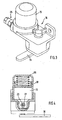
- the lubricant pump 16 is shown in a perspective view and in Fig. 4 in a sectional view of FIG. 2 orthogonal view. From FIGS. 3 and 4 it can be seen that the lubricant reservoir 15 can be connected directly to the lubricant pump 16. In the lubricant reservoir 15, a certain amount of lubricant, which is sufficient over a predetermined period of use, for example, for about 3 years, be included.
- the lubricant is pressurized in the lubricant reservoir 15 via a lubricant follower piston 28 and a spiral spring 29, so that sufficient lubricant is always present at the cylinder openings 31, 32 of the cylinder insert 27.
- the fifth-wheel coupling or lubrication device according to the invention is characterized in that extremely reliable lubrication can be ensured even over a long period of use without having to be connected to external lubrication. Including the lubrication device, the fifth wheel remains a completely self-sufficient component.
Landscapes
- Engineering & Computer Science (AREA)
- General Engineering & Computer Science (AREA)
- Mechanical Engineering (AREA)
- Chemical & Material Sciences (AREA)
- Combustion & Propulsion (AREA)
- Transportation (AREA)
- General Details Of Gearings (AREA)
- Reciprocating Pumps (AREA)
- Prostheses (AREA)
- Compressors, Vaccum Pumps And Other Relevant Systems (AREA)
- Rolling Contact Bearings (AREA)
- Arrangement And Driving Of Transmission Devices (AREA)
- Pharmaceuticals Containing Other Organic And Inorganic Compounds (AREA)
- Braking Arrangements (AREA)
Description
- Die Erfindung betrifft eine Sattelkupplung zur Montage an einem Zugfahrzeug, um einen Anhänger am Zugfahrzeug anzukuppeln, wobei die Sattelkupplung ein fahrzeugseitiges Grundteil und eine gegenüber dem Grundteil verschwenkbare Auflageplatte aufweist.
- Eine Sattelkupplung ist dem Fachmann hinlänglich bekannt und in einer speziellen, keineswegs zwingenden Ausgestaltung beispielsweise in der DE 296 03 641 U1 oder US 2 468 013 beschrieben.
- Derartige Sattelkupplungen werden bislang entweder von einer externen Schmiereinrichtung mit Schmierstoff versorgt oder - unter Vermeidung einer Schmierstoffpumpe - durch eine mit Druck zu beaufschlagende bzw. beaufschlagte Schmierstoffbuchse, die direkt an der Sattelkupplung angebracht sein kann. Eine Sattelkupplung mit einem Fahrzeugseitigen Grundteil, einer gegenüber dem Grundteil verschwenkbaren Auflageplatte und einer Schmiereinrichtung ist bereits aus der EP 0507342 A1 bekannt, wobei die dort vorgeschlagene herkömmliche Schmiereinrichtung aus einem im Aufbau der Sattelkupplung vorgesehenen Schmiermittelkanal sowie einem Anschlussstück, an die eine Schmiermittelpresse bedarfsweise angeschlossen werden kann, besteht.
- Die Aufgabe der vorliegenden Erfindung besteht gegenüber dem geschilderten Stand der Technik darin, eine Sattelkupplung mit einem alternativen Schmierkonzept zu schaffen. Eine weitere Aufgabe besteht darin, eine entsprechende Schmiereinrichtung sowie ein Verfahren zur Schmierung einer Sattelkupplung vorzuschlagen.
- Diese Aufgaben werden in vorrichtungstechnischer Hinsicht durch die Merkmale der Patentansprüche 1 bzw. 7 und in verfahrenstechnischer Hinsicht durch die Merkmale des Patentanspruchs 8 gelöst.
- Eine Kernüberlegung der vorliegenden Erfindung besteht darin, dass zunächst eine an der Sattelkupplung angeordnete Schmiereinrichtung geschaffen wird, die eine eigene Schmierstoffpumpe umfasst. Dieser übergeordnete Aspekt der vorliegenden Erfindung wird durch eine besonders zweckmäßige Lösung hinsichtlich der Energieversorgung der an der Sattelkupplung vorgesehenen Schmierstoffpumpe weiter konkretisiert. Die Schmierstoffpumpe an der Sattelkupplung wird durch diesen weiteren Kerngedanken der vorliegenden Erfindung nämlich durch die Schwenkbewegung der Auflageplatte relativ zum Grundteil bzw. zum Zugfahrzeug angetrieben. Der Antrieb erfolgt durch Wirkübertragungsmittel, welche die Schwenkbewegung aufnehmen.
- In einer konkreten Ausgestaltung umfassen die Wirkübertragungsmittel einen Antriebshebel zur Übertragung der Schwenkbewegung und einen Freilauf. Der Freilauf kann insbesondere als Hülsenfreilauf ausgebildet sein. Er hat den Zweck, die vom Antriebshebel ausgeübte Hin- und Herbewegung in eine einseitig gerichtete Drehbewegung zu überführen, so dass die Drehrichtung stets gleich bleibt.
- In einer konkreten Ausgestaltung ist der Freilauf auf einer Welle angeordnet derart, dass die Hin- und Herbewegung des Antriebshebels eine Drehbewegung der Welle zum Antrieb der Schmierstoffpumpe bewirkt.
- In einer bevorzugten Ausgestaltung umfasst die Schmierstoffpumpe einen in einem Zylinder gelagerten Kolben, wobei der Kolben über einen mit der Welle verbundenen Exzenter angetrieben wird. Über den Exzenter lässt sich ein gewünschter Verlauf des Kolbenhubes einstellen.
- In einer konkreten Ausgestaltung der vorliegenden Erfindung sind weiterhin Dosierungsmittel vorgesehen, um eine gewünschte Dosierung bezogen auf die Schwenkbewegungen der Sattelkupplung einstellen zu können. Hierzu kann beispielsweise das Ansaugvolumen des Zylinders pro Kolbenhub eingestellt werden. Selbstverständlich sind aber auch andere Dosierungsmittel möglich, die bei einer bestimmten Abfolge von Schwenkbewegungen der Sattelkupplung die Abgabe einer jeweils gewünschten, vorbestimmten Menge an Schmierstoff an eine Schmierstelle festlegen.
- Obwohl prinzipiell in vielen Fällen die Versorgung einer einzigen Schmierstelle, beispielsweise einer zentralen Schmierstelle an der Auflageplatte ausreichend sein kann, ist mit der erfindungsgemäßen Lösung auch die Versorgung mehrerer Schmierstellen an der Sattelkupplung möglich. In einer konkreten Ausgestaltung kann hierfür der Schmierstoffpumpe ein Verteiler, insbesondere ein Progressivverteiler nachgeschaltet sein, um mehrere Schmierstellen mit Schmierstoff zu versorgen. Alternativ ist es natürlich auch denkbar, an einer Sattelkupplung mehrere Schmierstoffpumpen vorzusehen, die jeweils mit zugeordneten Schmierstellen in Fluidverbindung stehen. Die Schmierstoffpumpen können dabei entweder durch einen gemeinsamen Exzenter oder durch jeweils separate Wirkübertragungsmittel durch die Schwenkbewegung der Auflageplatte angetrieben werden.
- Schmierstellen können bei der erfindungsgemäßen Schmiereinrichtung insbesondere an der Verriegelung der Sattelkupplung und/oder an der Auflageplatte der Sattelkupplung und/oder an der Schwenkachse zwischen Auflageplatte und Grundteil ausgebildet sein.
- Weiterhin wird erfindungsgemäß auch ein Verfahren zur Schmierung einer Sattelkupplung beansprucht, die an einem Zugfahrzeug montiert ist, wobei die Sattelkupplung ein fahrzeugseitiges Grundteil und eine gegenüber dem Grundteil verschwenkbare Auflageplatte aufweist, wobei die Schwenkbewegungen der Auflageplatte relativ zum Grundteil bzw. zum Zugfahrzeug ausgenutzt werden, um die Schmierstoffpumpe anzutreiben.
- Auflageplatte und Grundteil sind im Rahmen der Erfindung so zu verstehen, dass zwei durch Relativbewegungen zwischen Zugfahrzeug und Anhänger im angekuppelten Zustand zu Schwenkbewegungen angetriebene Teile der Sattelkupplung gemeint sind, wobei das Grundteil das kinematisch dem Zugfahrzeug näher gelegene und die Auflageplatte das kinematisch dem Anhänger näher gelegene Teil der Sattelkupplung bezeichnen soll. Weiter wird klargestellt, dass bevorzugtermaßen in erster Linie eine Schwenkbewegung zwischen Zugfahrzeug und Anhänger um eine quer zur Fahrtrichtung horizontale Achse ausgenutzt wird; es ist aber auch denkbar, Schwenkbewegungen um die Vertikalachse und/oder andere Schwenkbewegungen zum Antrieb der Schmierstoffpumpe auszunutzen.
- Die Erfindung wird nachstehend auch hinsichtlich weiterer Merkmale und Vorteile anhand der Beschreibung von Ausführungsbeispielen und unter Bezugnahme auf die beiliegenden Zeichnungen näher erläutert.
- Hierbei zeigen:
- Fig. 1
- eine Ausführungsform der erfindungsgemäßen Sattelkupplung mit Schmiereinrichtung mit perspektivischer Ansicht,
- Fig. 2
- die in der Ausführungsform nach Fig. 1 eingesetzte Schmierstoffpumpe in Querschnittsansicht,
- Fig. 3
- eine perspektivische Ansicht der Schmierstoffpumpe nach Fig. 2,
- Fig. 4
- eine zur Schnittansicht nach Fig. 2 orthogonale Schnittansicht durch die bei der Ausführungsform nach Fig. 1 eingesetzten Schmierstoffpumpe.
- In Fig. 1 ist eine Sattelkupplung 11 mit einer Schmiereinrichtung 14 nach der Erfindung in schematischer Perspektivansicht dargestellt. Die Sattelkupplung 11 umfasst zunächst eine etwa hufeisenförmige Auflageplatte 13, die an ihrer Unterseite gegenüber einem fahrzeugseitigen Grundteil 12 gelenkig gelagert ist. Das fahrzeugseitige Grundteil 12 besteht bei der vorliegenden Ausführungsform aus zwei voneinander getrennten Lagerböcken, die jeweils um einen Lagerbolzen 30 der Auflageplatte 13 verschwenkbar gelagert sind.
- Bei am Zugfahrzeug angekuppelten Anhänger gleicht die Schwenkbewegung zwischen Auflageplatte 13 und fahrzeugseitigem Grundteil 12 - hier in Form von zwei separaten Lagerböcken ausgebildet - Bewegungen aus, die bei Überfahren von Kuppen, Mulden, Bodenunebenheiten, etc. entstehen. Diese Schwenkbewegung wird zum Antrieb einer Schmierstoffpumpe 16 eingesetzt, die Bestandteil der bereits erwähnten Schmiereinrichtung 14 ist.
- Die Schmiereinrichtung 14 umfasst weiterhin ein in der vorliegenden Ausführungsform an der Schmierstoffpumpe 16 angebrachtes Schmierstoffreservoir 15 sowie mindestens eine Schmierstelle 17, die über eine Schmiermittelleitung 26 mit der Schmierstoffpumpe 16 in Fluidverbindung steht. Die Schmiermittelleitung 26 ist hier über einen pumpenseitigen Anschlussstutzen 25 mit der Schmierstoffpumpe 16 verbunden. Die Schmierstelle 17 ist hier rein schematisch dargestellt und befindet sich an sich auf der dem Grundteil 12 abgewandten Seite der Auflageplatte 13, um die Auflageplatte 13 mit Schmierstoff zu versorgen.
- Zur Aufnahme der Schwenkbewegungen zwischen Auflageplatte 13 und (fahrzeugseitigem) Grundteil 12, hier einem der beiden Lagerböcke sind Wirkübertragungsmittel 18, 19, 20, 23 vorgesehen, welche die Schwenkbewegung zwischen Auflageplatte 13 und (fahrzeugseitigem) Grundteil 12 zum Antrieb mindestens eines Kolbens 22 einer Schmierstoffpumpe 16 übersetzen. Konkret umfassen die Wirkübertragungsmittel bei der vorliegenden Ausführungsform, wie aus den Figuren 1 und 2 erkennbar einen an der Schmierstoffpumpe 16, die in der vorliegenden Ausführungsform an der Unterseite der Auflageplatte 13 befestigt ist, ausgehenden Antriebshebel 18, dessen distales Ende am fahrzeugseitigen Grundteil 12 befestigt ist.
- Bei der vorliegenden Ausführungsform ist die Anordnung in etwa so getroffen, dass der Pendelweg der Auflageplatte 13 relativ zum (fahrzeugseitigen) Grundteil 12 in etwa dem Hebelweg des Antriebshebels 18 entspricht. Es ist jedoch ohne weiteres ersichtlich, dass je nach Platzierung der Schmierstoffpumpe 16 bzw. der Befestigung bzw. Anlenkung des distalen Antriebshebels des Antriebshebels 18 auch andere Übersetzungsverhältnisse vorgegeben werden können. Ebenfalls ist es ohne weiteres denkbar, die Schmierstoffpumpe 16 an einem gegenüber dem Zugfahrzeug festen Teil, insbesondere dem (fahrzeugseitigen) Grundteil 12 zu befestigen und das distale Ende des Antriebshebels 18 mit einem Teil, das den Schwenkbewegungen der Auflageplatte 13 folgt oder mit der Auflageplatte 13 selbst zu verbinden.
- Wie aus Fig. 2 erkennbar, werden die Hin- und Herbewegungen des Antriebshebels 18 auf einen Exzenter 23 der Schmierstoffpumpe 16 übertragen, wobei der Exzenter 23 einen in einem Zylinder 21 gelagerten Kolben 22 der Schmierstoffpumpe antreibt. Um zu verhindern, dass sich der Exzenter 23 mit Hin- und Herbewegung des Antriebshebels 18 ebenfalls hin- und herbewegt, ist auf einer gemeinsamen Welle 20 ein Freilauf 19 vorgesehen, der bewirkt, dass die Hin- und Herbewegung des Antriebshebels 18 in eine nur in einem Drehsinn gerichtet Antriebsbewegung überführt wird. Der Freilauf 19 ist hier als Hülsenfreilauf ausgebildet.
- In einer bevorzugten, hier dargestellten Ausführungsform lässt sich die Dosiermenge der Schmierstoffpumpe 16 durch Dosierungseinstellmittel 24 über einen gewissen Bereich einstellen. In der hier konkret dargestellten Ausführungsform umfassen die Dosierungseinstellmittel 24 einen Zylindereinsatz 27, der gegenüber der Welle 20 und dem Exzenter 23 in seiner axialen Lage, beispielsweise durch Verschrauben in einem Gewinde verändert werden kann. Der Zylindereinsatz 27 bildet den für den Pumpvorgang maßgeblichen Zylinder 21, in dem der Kolben 22 gelagert ist, aus. Durch axiale Verlagerung des Zylindereinsatzes 27, die durch ein Herein- oder Herausschrauben des Zylindereinsatzes 27 erreicht werden kann, verändert sich das wirksame Pumpvolumen, da Zylinderöffnungen 31, 32 je nach Lage des Zylindereinsatzes bei einem Hubzyklus früher oder später freigegeben werden und entsprechend früher bzw. später das Zuströmen von Schmiermittel gestatten.
- In Fig. 3 ist die Schmierstoffpumpe 16 in perspektivischer Ansicht und in Fig. 4 in einer zur Schnittansicht nach Fig. 2 orthogonalen Ansicht dargestellt. Aus den Figuren 3 und 4 lässt sich erkennen, dass an der Schmierstoffpumpe 16 unmittelbar das Schmierstoffreservoir 15 angeschlossen sein kann. Im Schmierstoffreservoir 15 kann eine bestimmte Menge Schmierstoff, der über einen vorgegebenen Nutzungszeitraum, beispielsweise für ca. 3 Jahre ausreichend ist, aufgenommen sein. Der Schmierstoff wird im Schmierstoffreservoir 15 über einen Schmierstofffolgekolben 28 und eine Spiralfeder 29 mit Druck beaufschlagt, so dass stets ausreichend Schmierstoff an den Zylinderöffnungen 31, 32 des Zylindereinsatzes 27 ansteht.
- Die erfindungsgemäße Sattelkupplung bzw. die Schmiereinrichtung zeichnen sich dadurch aus, dass eine äußerst zuverlässige Schmierung auch über einen langen Nutzungszeitraum sichergestellt werden kann, ohne dass ein Anschluss an eine externe Schmierung vorgenommen werden muss. Die Sattelkupplung bleibt damit inkl. der Schmiereinrichtung ein komplett autarkes Bauteil.
-
- 11
- Sattelkupplung
- 12
- (fahrzeugseitiges) Grundteil
- 13
- Auflageplatte
- 14
- Schmiereinrichtung
- 15
- Schmierstoffreservoir
- 16
- Schmierstoffpumpe
- 17
- Schmierstelle
- 18
- Wirkübertragungsmittel, Antriebshebel
- 19
- Wirkübertragungsmittel, Freilauf
- 20
- Wirkübertragungsmittel, Welle
- 21
- Zylinder
- 22
- Kolben
- 23
- Wirkübrtragungsmittel, Exzenter
- 24
- Dosierungseinstellmittel
- 25
- Anschlussstutzen
- 26
- Schmiermittelleitung
- 27
- Zylindereinsatz
- 28
- Schmierstofffolgekolben
- 29
- Spiralfeder
- 30
- Lagerbolzen
- 31, 32
- Zylinderöffnungen
Claims (8)
- Sattelkupplung zur Montage an einem Zugfahrzeug, um einen Anhänger am Zugfahrzeug anzukuppeln,- wobei die Sattelkupplung (11) ein fahrzeugseitiges Grundteil (12) und eine gegenüber dem Grundteil (12) verschwenkbare Auflageplatte (13) aufweist,- wobei die Sattelkupplung (11) weiterhin eine Schmiereinrichtung (14) mit einem Schmierstoffreservoir (15), einer Schmierstoffpumpe (16) und mindestens einer von der Schmierstoffpumpe (16) aus dem Schmierstoffreservoir (15) mit Schmierstoff versorgten Schmierstelle (17) umfasst, und- wobei die Schmierstoffpumpe (16) durch die Schwenkbewegung der Auflageplatte (13) relativ zum Grundteil (12) bzw. zum Zugfahrzeug aufnehmende Wirkübertragungsmittel (18 bis 20, 23) angetrieben wird.
- Sattelkupplung nach Anspruch 1,
dadurch gekennzeichnet,
dass die Wirkübertragungsmittel einen Antriebshebel (18) zur Übertragung der Schwenkbewegung und einen Freilauf (19) umfassen. - Sattelkupplung nach Anspruch 2,
dadurch gekennzeichnet,
dass der Freilauf (19) auf einer Welle (20) angeordnet ist derart, dass eine Hin- und Herbewegung des Antriebshebels (18) eine Drehbewegung der Welle (20) zum Antrieb der Schmierstoffpumpe (16) bewirkt. - Sattelkupplung nach einem der Ansprüche 1 bis 3,
dadurch gekennzeichnet,
dass die Schmierstoffpumpe (16) einen in einem Zylinder (21) gelagerten Kolben (22) umfasst und dass der Kolben (22) über einen mit der Welle (20) verbundenen Exzenter (23) angetrieben wird. - Sattelkupplung nach Anspruch 4,
dadurch gekennzeichnet,
dass Dosierungsmittel (24) an der Schmierstoffpumpe (16) vorgesehen sind, um ein gewünschtes Ansaugvolumen des Zylinders (21) pro Kolbenhub einstellen zu können - Sattelkupplung nach einem der Ansprüche 1 bis 5,
dadurch gekennzeichnet,
dass der Schmierstoffpumpe (16) ein Verteiler, insbesondere ein Progressivverteiler nachgeschaltet ist, um mehrere Schmierstellen (17) mit Schmierstoff zu versorgen. - Sattelkupplung nach einem der Ansprüche 1 bis 6,
dadurch gekennzeichnet,
dass die mit der Schmierstoffpumpe (16) in Fluidverbindung stehenden Schmierstellen (17) an der Verriegelung der Sattelkupplung (11) und/oder an der Auflageplatte (13) und/oder an der Schwenkachse zwischen Auflageplatte (13) und Grundteil (12) ausgebildet sind. - Verfahren zur Schmierung einer Sattelkupplung (11), die an einem Zugfahrzeug montiert ist, wobei die Sattelkupplung (11) ein fahrzeugseitiges Grundteil (12) und eine gegenüber dem Grundteil (12) verschwenkbare Auflageplatte (13) aufweist,
dadurch gekennzeichnet,
dass die Schwenkbewegungen der Auflageplatte (13) relativ zum Grundteil (12) bzw. zum Zugfahrzeug ausgenutzt werden, um eine Schmierstoffpumpe (16) anzutreiben.
Priority Applications (2)
| Application Number | Priority Date | Filing Date | Title |
|---|---|---|---|
| PL04016701T PL1514774T3 (pl) | 2003-09-09 | 2004-07-15 | Sprzęg siodłowy |
| EP06022255A EP1741620A1 (de) | 2003-09-09 | 2004-07-15 | Sattelkupplung |
Applications Claiming Priority (2)
| Application Number | Priority Date | Filing Date | Title |
|---|---|---|---|
| DE10341880 | 2003-09-09 | ||
| DE10341880A DE10341880A1 (de) | 2003-09-09 | 2003-09-09 | Sattelkupplung |
Related Child Applications (1)
| Application Number | Title | Priority Date | Filing Date |
|---|---|---|---|
| EP06022255A Division EP1741620A1 (de) | 2003-09-09 | 2004-07-15 | Sattelkupplung |
Publications (2)
| Publication Number | Publication Date |
|---|---|
| EP1514774A1 EP1514774A1 (de) | 2005-03-16 |
| EP1514774B1 true EP1514774B1 (de) | 2006-10-25 |
Family
ID=34129743
Family Applications (2)
| Application Number | Title | Priority Date | Filing Date |
|---|---|---|---|
| EP04016701A Expired - Lifetime EP1514774B1 (de) | 2003-09-09 | 2004-07-15 | Sattelkupplung |
| EP06022255A Ceased EP1741620A1 (de) | 2003-09-09 | 2004-07-15 | Sattelkupplung |
Family Applications After (1)
| Application Number | Title | Priority Date | Filing Date |
|---|---|---|---|
| EP06022255A Ceased EP1741620A1 (de) | 2003-09-09 | 2004-07-15 | Sattelkupplung |
Country Status (5)
| Country | Link |
|---|---|
| EP (2) | EP1514774B1 (de) |
| AT (1) | ATE343510T1 (de) |
| DE (3) | DE10341880A1 (de) |
| ES (1) | ES2274352T3 (de) |
| PL (1) | PL1514774T3 (de) |
Families Citing this family (3)
| Publication number | Priority date | Publication date | Assignee | Title |
|---|---|---|---|---|
| DE102005007144B4 (de) † | 2005-02-11 | 2008-10-02 | Jost-Werke Gmbh | Schmiersystem für eine Sattelkupplung eines Zugfahrzeuges |
| EP2072883B1 (de) * | 2007-12-19 | 2016-04-27 | Caterpillar Commercial S.A.R.L. | Schmiersystem und Verfahren für Fahrzeuge, die mit einem Klingenelement versehen sind |
| EP3683441B1 (de) * | 2019-01-16 | 2024-08-28 | Groeneveld-BEKA GmbH | Montageeinheit als baugruppe für eine schmierstoffpumpe |
Family Cites Families (12)
| Publication number | Priority date | Publication date | Assignee | Title |
|---|---|---|---|---|
| US1609695A (en) * | 1925-11-16 | 1926-12-07 | Olive A Day | Automatic lubricator |
| US1877070A (en) * | 1926-04-28 | 1932-09-13 | George R Siegrist | Lubricating system |
| DE476569C (de) * | 1928-02-12 | 1929-05-22 | August Enders Akt Ges | An Fahrzeugen angeordnete Hochdruckschmierpresse fuer konsistentes Fett |
| US2468013A (en) * | 1946-08-31 | 1949-04-19 | American Steel Foundries | Fifth-wheel mounting |
| US4477100A (en) | 1980-12-02 | 1984-10-16 | Amir Elyakim | Fifth wheel coupling apparatus |
| DE3815233A1 (de) * | 1988-05-05 | 1989-11-16 | Baier & Koeppel | Antrieb fuer eine schmiermittelpumpe |
| DE4110893A1 (de) * | 1991-04-04 | 1992-10-08 | Rockinger Spezial Fab Joh | Schmiermittelversorgung fuer den schlossbereich einer sattelkupplung |
| US5417308A (en) | 1993-08-09 | 1995-05-23 | Hartl; Toby L. | Trailer fifth wheel lubrication apparatus |
| US5746438A (en) * | 1995-03-03 | 1998-05-05 | Jost--Werke AG | Fifth wheel |
| DE10118284A1 (de) * | 2000-10-28 | 2002-05-29 | Lincoln Gmbh | Selbsttätige Schmiereinrichtung |
| DE20019186U1 (de) * | 2000-11-10 | 2001-01-11 | Baier & Köppel GmbH & Co, 91257 Pegnitz | Fahrzeuggebundene Zentralschmieranlage |
| DE20206050U1 (de) * | 2002-04-18 | 2002-07-25 | Lincoln GmbH & Co. KG, 69190 Walldorf | Selbsttätige Schmiereinrichtung |
-
2003
- 2003-09-09 DE DE10341880A patent/DE10341880A1/de not_active Withdrawn
- 2003-09-09 DE DE20321069U patent/DE20321069U1/de not_active Expired - Lifetime
-
2004
- 2004-07-15 AT AT04016701T patent/ATE343510T1/de active
- 2004-07-15 PL PL04016701T patent/PL1514774T3/pl unknown
- 2004-07-15 ES ES04016701T patent/ES2274352T3/es not_active Expired - Lifetime
- 2004-07-15 EP EP04016701A patent/EP1514774B1/de not_active Expired - Lifetime
- 2004-07-15 EP EP06022255A patent/EP1741620A1/de not_active Ceased
- 2004-07-15 DE DE502004001842T patent/DE502004001842D1/de not_active Expired - Lifetime
Also Published As
| Publication number | Publication date |
|---|---|
| DE502004001842D1 (de) | 2006-12-07 |
| EP1514774A1 (de) | 2005-03-16 |
| DE10341880A1 (de) | 2005-04-14 |
| ES2274352T3 (es) | 2007-05-16 |
| DE20321069U1 (de) | 2005-12-29 |
| ATE343510T1 (de) | 2006-11-15 |
| PL1514774T3 (pl) | 2007-03-30 |
| EP1741620A1 (de) | 2007-01-10 |
Similar Documents
| Publication | Publication Date | Title |
|---|---|---|
| DE69518933T3 (de) | Bremsbetätigungsmechanismus für einen Bremssattel | |
| EP2576247B1 (de) | Einzelradaufhängung für ein gefedertes, lenkbares rad | |
| EP1475253A1 (de) | Anhängekupplung für Kraftfahrzeuge | |
| DE2121381A1 (de) | Lenkung mit Zahnstange und Ritzel | |
| EP0154799A2 (de) | Nachstellvorrichtung für Fahrzeugbremsen | |
| EP1514774B1 (de) | Sattelkupplung | |
| DE20307381U1 (de) | Höhenverstellbare Stütze für Sattelauflieger o.dgl. | |
| EP1247715A1 (de) | Zug- und Stosseinrichtung für Schienenfahrzeuge | |
| DE3345293C2 (de) | ||
| DE19954927A1 (de) | Kolbenmaschine und Verteilelement | |
| DE102018129285A1 (de) | Radlager für ein Kraftfahrzeug | |
| DE3140185A1 (de) | "fahrwerk fuer ein luftfahrzeug" | |
| DE2138291A1 (de) | Hydraulische Lenkung | |
| DE476569C (de) | An Fahrzeugen angeordnete Hochdruckschmierpresse fuer konsistentes Fett | |
| EP1614557B1 (de) | Anhängekupplung für Kraftfahrzeuge | |
| DE202009015102U1 (de) | Aufliegerfahrzeug mit einer Lenkvorrichtung | |
| DE3700670A1 (de) | Achsanordnung fuer einen eisenbahnwaggon | |
| WO2015070863A2 (de) | Ausrückvorrichtung | |
| DE385914C (de) | Schmiervorrichtung fuer die Gleisketten von Fahrzeugen | |
| DE91559C (de) | ||
| DE821764C (de) | Kolbenpumpe | |
| DE4402995C1 (de) | Klotzbremseinheit für Schienenfahrzeuge | |
| DE577092C (de) | Lagerung der hohlen, Schmiermittel enthaltenden Federbolzen in den die Feder mit dem Rahmen oder der Radachse verbindenden Lenkern, insbesondere fuer Kraftfahrzeuge | |
| DE1655341C3 (de) | Abschmiersystem für Fahrzeuge | |
| DE8516062U1 (de) | Schrankenantrieb |
Legal Events
| Date | Code | Title | Description |
|---|---|---|---|
| PUAI | Public reference made under article 153(3) epc to a published international application that has entered the european phase |
Free format text: ORIGINAL CODE: 0009012 |
|
| AK | Designated contracting states |
Kind code of ref document: A1 Designated state(s): AT BE BG CH CY CZ DE DK EE ES FI FR GB GR HU IE IT LI LU MC NL PL PT RO SE SI SK TR |
|
| AX | Request for extension of the european patent |
Extension state: AL HR LT LV MK |
|
| 17P | Request for examination filed |
Effective date: 20050503 |
|
| AKX | Designation fees paid |
Designated state(s): AT BE BG CH CY CZ DE DK EE ES FI FR GB GR HU IE IT LI LU MC NL PL PT RO SE SI SK TR |
|
| GRAP | Despatch of communication of intention to grant a patent |
Free format text: ORIGINAL CODE: EPIDOSNIGR1 |
|
| GRAS | Grant fee paid |
Free format text: ORIGINAL CODE: EPIDOSNIGR3 |
|
| GRAA | (expected) grant |
Free format text: ORIGINAL CODE: 0009210 |
|
| AK | Designated contracting states |
Kind code of ref document: B1 Designated state(s): AT BE BG CH CY CZ DE DK EE ES FI FR GB GR HU IE IT LI LU MC NL PL PT RO SE SI SK TR |
|
| PG25 | Lapsed in a contracting state [announced via postgrant information from national office to epo] |
Ref country code: FI Free format text: LAPSE BECAUSE OF FAILURE TO SUBMIT A TRANSLATION OF THE DESCRIPTION OR TO PAY THE FEE WITHIN THE PRESCRIBED TIME-LIMIT Effective date: 20061025 Ref country code: CZ Free format text: LAPSE BECAUSE OF FAILURE TO SUBMIT A TRANSLATION OF THE DESCRIPTION OR TO PAY THE FEE WITHIN THE PRESCRIBED TIME-LIMIT Effective date: 20061025 Ref country code: SK Free format text: LAPSE BECAUSE OF FAILURE TO SUBMIT A TRANSLATION OF THE DESCRIPTION OR TO PAY THE FEE WITHIN THE PRESCRIBED TIME-LIMIT Effective date: 20061025 Ref country code: RO Free format text: LAPSE BECAUSE OF FAILURE TO SUBMIT A TRANSLATION OF THE DESCRIPTION OR TO PAY THE FEE WITHIN THE PRESCRIBED TIME-LIMIT Effective date: 20061025 Ref country code: IE Free format text: LAPSE BECAUSE OF FAILURE TO SUBMIT A TRANSLATION OF THE DESCRIPTION OR TO PAY THE FEE WITHIN THE PRESCRIBED TIME-LIMIT Effective date: 20061025 Ref country code: SI Free format text: LAPSE BECAUSE OF FAILURE TO SUBMIT A TRANSLATION OF THE DESCRIPTION OR TO PAY THE FEE WITHIN THE PRESCRIBED TIME-LIMIT Effective date: 20061025 |
|
| REG | Reference to a national code |
Ref country code: GB Ref legal event code: FG4D Free format text: NOT ENGLISH |
|
| REG | Reference to a national code |
Ref country code: CH Ref legal event code: EP |
|
| REG | Reference to a national code |
Ref country code: IE Ref legal event code: FG4D Free format text: LANGUAGE OF EP DOCUMENT: GERMAN |
|
| REF | Corresponds to: |
Ref document number: 502004001842 Country of ref document: DE Date of ref document: 20061207 Kind code of ref document: P |
|
| PG25 | Lapsed in a contracting state [announced via postgrant information from national office to epo] |
Ref country code: BG Free format text: LAPSE BECAUSE OF FAILURE TO SUBMIT A TRANSLATION OF THE DESCRIPTION OR TO PAY THE FEE WITHIN THE PRESCRIBED TIME-LIMIT Effective date: 20070125 Ref country code: DK Free format text: LAPSE BECAUSE OF FAILURE TO SUBMIT A TRANSLATION OF THE DESCRIPTION OR TO PAY THE FEE WITHIN THE PRESCRIBED TIME-LIMIT Effective date: 20070125 |
|
| GBT | Gb: translation of ep patent filed (gb section 77(6)(a)/1977) |
Effective date: 20070108 |
|
| REG | Reference to a national code |
Ref country code: SE Ref legal event code: TRGR |
|
| REG | Reference to a national code |
Ref country code: CH Ref legal event code: NV Representative=s name: ISLER & PEDRAZZINI AG |
|
| PG25 | Lapsed in a contracting state [announced via postgrant information from national office to epo] |
Ref country code: PT Free format text: LAPSE BECAUSE OF FAILURE TO SUBMIT A TRANSLATION OF THE DESCRIPTION OR TO PAY THE FEE WITHIN THE PRESCRIBED TIME-LIMIT Effective date: 20070326 |
|
| REG | Reference to a national code |
Ref country code: PL Ref legal event code: T3 |
|
| REG | Reference to a national code |
Ref country code: ES Ref legal event code: FG2A Ref document number: 2274352 Country of ref document: ES Kind code of ref document: T3 |
|
| ET | Fr: translation filed | ||
| REG | Reference to a national code |
Ref country code: IE Ref legal event code: FD4D |
|
| PLBE | No opposition filed within time limit |
Free format text: ORIGINAL CODE: 0009261 |
|
| STAA | Information on the status of an ep patent application or granted ep patent |
Free format text: STATUS: NO OPPOSITION FILED WITHIN TIME LIMIT |
|
| REG | Reference to a national code |
Ref country code: CH Ref legal event code: PCAR Free format text: ISLER & PEDRAZZINI AG;POSTFACH 1772;8027 ZUERICH (CH) |
|
| 26N | No opposition filed |
Effective date: 20070726 |
|
| BERE | Be: lapsed |
Owner name: BAIER & KOPPEL G.M.B.H. & CO. Effective date: 20070731 |
|
| PG25 | Lapsed in a contracting state [announced via postgrant information from national office to epo] |
Ref country code: GR Free format text: LAPSE BECAUSE OF FAILURE TO SUBMIT A TRANSLATION OF THE DESCRIPTION OR TO PAY THE FEE WITHIN THE PRESCRIBED TIME-LIMIT Effective date: 20070126 Ref country code: MC Free format text: LAPSE BECAUSE OF NON-PAYMENT OF DUE FEES Effective date: 20070731 |
|
| PG25 | Lapsed in a contracting state [announced via postgrant information from national office to epo] |
Ref country code: BE Free format text: LAPSE BECAUSE OF NON-PAYMENT OF DUE FEES Effective date: 20070731 |
|
| PG25 | Lapsed in a contracting state [announced via postgrant information from national office to epo] |
Ref country code: EE Free format text: LAPSE BECAUSE OF FAILURE TO SUBMIT A TRANSLATION OF THE DESCRIPTION OR TO PAY THE FEE WITHIN THE PRESCRIBED TIME-LIMIT Effective date: 20061025 |
|
| PG25 | Lapsed in a contracting state [announced via postgrant information from national office to epo] |
Ref country code: LU Free format text: LAPSE BECAUSE OF NON-PAYMENT OF DUE FEES Effective date: 20070715 Ref country code: CY Free format text: LAPSE BECAUSE OF FAILURE TO SUBMIT A TRANSLATION OF THE DESCRIPTION OR TO PAY THE FEE WITHIN THE PRESCRIBED TIME-LIMIT Effective date: 20061025 |
|
| PG25 | Lapsed in a contracting state [announced via postgrant information from national office to epo] |
Ref country code: HU Free format text: LAPSE BECAUSE OF FAILURE TO SUBMIT A TRANSLATION OF THE DESCRIPTION OR TO PAY THE FEE WITHIN THE PRESCRIBED TIME-LIMIT Effective date: 20070426 Ref country code: TR Free format text: LAPSE BECAUSE OF FAILURE TO SUBMIT A TRANSLATION OF THE DESCRIPTION OR TO PAY THE FEE WITHIN THE PRESCRIBED TIME-LIMIT Effective date: 20061025 |
|
| PGFP | Annual fee paid to national office [announced via postgrant information from national office to epo] |
Ref country code: DE Payment date: 20100928 Year of fee payment: 7 |
|
| PGFP | Annual fee paid to national office [announced via postgrant information from national office to epo] |
Ref country code: PL Payment date: 20110527 Year of fee payment: 8 |
|
| PGFP | Annual fee paid to national office [announced via postgrant information from national office to epo] |
Ref country code: CH Payment date: 20110801 Year of fee payment: 8 |
|
| PGFP | Annual fee paid to national office [announced via postgrant information from national office to epo] |
Ref country code: ES Payment date: 20110825 Year of fee payment: 8 Ref country code: SE Payment date: 20110726 Year of fee payment: 8 Ref country code: GB Payment date: 20110729 Year of fee payment: 8 Ref country code: FR Payment date: 20110810 Year of fee payment: 8 Ref country code: AT Payment date: 20110728 Year of fee payment: 8 |
|
| PGFP | Annual fee paid to national office [announced via postgrant information from national office to epo] |
Ref country code: IT Payment date: 20110727 Year of fee payment: 8 Ref country code: NL Payment date: 20110801 Year of fee payment: 8 |
|
| REG | Reference to a national code |
Ref country code: NL Ref legal event code: V1 Effective date: 20130201 |
|
| REG | Reference to a national code |
Ref country code: CH Ref legal event code: PL |
|
| REG | Reference to a national code |
Ref country code: SE Ref legal event code: EUG |
|
| REG | Reference to a national code |
Ref country code: AT Ref legal event code: MM01 Ref document number: 343510 Country of ref document: AT Kind code of ref document: T Effective date: 20120715 |
|
| GBPC | Gb: european patent ceased through non-payment of renewal fee |
Effective date: 20120715 |
|
| REG | Reference to a national code |
Ref country code: FR Ref legal event code: ST Effective date: 20130329 |
|
| PG25 | Lapsed in a contracting state [announced via postgrant information from national office to epo] |
Ref country code: LI Free format text: LAPSE BECAUSE OF NON-PAYMENT OF DUE FEES Effective date: 20120731 Ref country code: DE Free format text: LAPSE BECAUSE OF NON-PAYMENT OF DUE FEES Effective date: 20130201 Ref country code: CH Free format text: LAPSE BECAUSE OF NON-PAYMENT OF DUE FEES Effective date: 20120731 Ref country code: NL Free format text: LAPSE BECAUSE OF NON-PAYMENT OF DUE FEES Effective date: 20130201 Ref country code: GB Free format text: LAPSE BECAUSE OF NON-PAYMENT OF DUE FEES Effective date: 20120715 Ref country code: FR Free format text: LAPSE BECAUSE OF NON-PAYMENT OF DUE FEES Effective date: 20120731 Ref country code: SE Free format text: LAPSE BECAUSE OF NON-PAYMENT OF DUE FEES Effective date: 20120716 |
|
| PG25 | Lapsed in a contracting state [announced via postgrant information from national office to epo] |
Ref country code: IT Free format text: LAPSE BECAUSE OF NON-PAYMENT OF DUE FEES Effective date: 20120715 |
|
| PG25 | Lapsed in a contracting state [announced via postgrant information from national office to epo] |
Ref country code: AT Free format text: LAPSE BECAUSE OF NON-PAYMENT OF DUE FEES Effective date: 20120715 |
|
| REG | Reference to a national code |
Ref country code: DE Ref legal event code: R119 Ref document number: 502004001842 Country of ref document: DE Effective date: 20130201 |
|
| REG | Reference to a national code |
Ref country code: ES Ref legal event code: FD2A Effective date: 20131018 |
|
| PG25 | Lapsed in a contracting state [announced via postgrant information from national office to epo] |
Ref country code: ES Free format text: LAPSE BECAUSE OF NON-PAYMENT OF DUE FEES Effective date: 20120716 |
|
| REG | Reference to a national code |
Ref country code: PL Ref legal event code: LAPE |
|
| PG25 | Lapsed in a contracting state [announced via postgrant information from national office to epo] |
Ref country code: PL Free format text: LAPSE BECAUSE OF NON-PAYMENT OF DUE FEES Effective date: 20120715 |