EP1514752B1 - Bras d'essuie-glace - Google Patents
Bras d'essuie-glace Download PDFInfo
- Publication number
- EP1514752B1 EP1514752B1 EP03103349A EP03103349A EP1514752B1 EP 1514752 B1 EP1514752 B1 EP 1514752B1 EP 03103349 A EP03103349 A EP 03103349A EP 03103349 A EP03103349 A EP 03103349A EP 1514752 B1 EP1514752 B1 EP 1514752B1
- Authority
- EP
- European Patent Office
- Prior art keywords
- windscreen wiper
- groove
- mounting head
- side walls
- protrusion
- Prior art date
- Legal status (The legal status is an assumption and is not a legal conclusion. Google has not performed a legal analysis and makes no representation as to the accuracy of the status listed.)
- Expired - Fee Related
Links
Images


Classifications
-
- B—PERFORMING OPERATIONS; TRANSPORTING
- B60—VEHICLES IN GENERAL
- B60S—SERVICING, CLEANING, REPAIRING, SUPPORTING, LIFTING, OR MANOEUVRING OF VEHICLES, NOT OTHERWISE PROVIDED FOR
- B60S1/00—Cleaning of vehicles
- B60S1/02—Cleaning windscreens, windows or optical devices
- B60S1/04—Wipers or the like, e.g. scrapers
- B60S1/32—Wipers or the like, e.g. scrapers characterised by constructional features of wiper blade arms or blades
- B60S1/34—Wiper arms; Mountings therefor
- B60S1/3425—Constructional aspects of the arm
- B60S1/3445—Joints between elements
- B60S1/345—Joints between elements the elements being a link piece and a mounting head
-
- B—PERFORMING OPERATIONS; TRANSPORTING
- B60—VEHICLES IN GENERAL
- B60S—SERVICING, CLEANING, REPAIRING, SUPPORTING, LIFTING, OR MANOEUVRING OF VEHICLES, NOT OTHERWISE PROVIDED FOR
- B60S1/00—Cleaning of vehicles
- B60S1/02—Cleaning windscreens, windows or optical devices
- B60S1/04—Wipers or the like, e.g. scrapers
- B60S1/32—Wipers or the like, e.g. scrapers characterised by constructional features of wiper blade arms or blades
- B60S1/34—Wiper arms; Mountings therefor
-
- B—PERFORMING OPERATIONS; TRANSPORTING
- B60—VEHICLES IN GENERAL
- B60S—SERVICING, CLEANING, REPAIRING, SUPPORTING, LIFTING, OR MANOEUVRING OF VEHICLES, NOT OTHERWISE PROVIDED FOR
- B60S1/00—Cleaning of vehicles
- B60S1/02—Cleaning windscreens, windows or optical devices
- B60S1/04—Wipers or the like, e.g. scrapers
- B60S1/32—Wipers or the like, e.g. scrapers characterised by constructional features of wiper blade arms or blades
- B60S1/38—Wiper blades
- B60S1/3848—Flat-type wiper blade, i.e. without harness
- B60S1/3886—End caps
- B60S1/3887—Mounting of end caps
- B60S1/3889—Mounting of end caps cooperating with holes in the vertebra
-
- B—PERFORMING OPERATIONS; TRANSPORTING
- B60—VEHICLES IN GENERAL
- B60S—SERVICING, CLEANING, REPAIRING, SUPPORTING, LIFTING, OR MANOEUVRING OF VEHICLES, NOT OTHERWISE PROVIDED FOR
- B60S1/00—Cleaning of vehicles
- B60S1/02—Cleaning windscreens, windows or optical devices
- B60S1/04—Wipers or the like, e.g. scrapers
- B60S1/32—Wipers or the like, e.g. scrapers characterised by constructional features of wiper blade arms or blades
- B60S1/38—Wiper blades
- B60S2001/3812—Means of supporting or holding the squeegee or blade rubber
- B60S2001/3817—Means of supporting or holding the squeegee or blade rubber chacterised by a backing strip to aid mounting of squeegee in support
- B60S2001/382—Means of supporting or holding the squeegee or blade rubber chacterised by a backing strip to aid mounting of squeegee in support the backing strip being an essentially planar reinforcing strip, e.g. vertebra
-
- B—PERFORMING OPERATIONS; TRANSPORTING
- B60—VEHICLES IN GENERAL
- B60S—SERVICING, CLEANING, REPAIRING, SUPPORTING, LIFTING, OR MANOEUVRING OF VEHICLES, NOT OTHERWISE PROVIDED FOR
- B60S1/00—Cleaning of vehicles
- B60S1/02—Cleaning windscreens, windows or optical devices
- B60S1/04—Wipers or the like, e.g. scrapers
- B60S1/32—Wipers or the like, e.g. scrapers characterised by constructional features of wiper blade arms or blades
- B60S1/38—Wiper blades
- B60S2001/3812—Means of supporting or holding the squeegee or blade rubber
- B60S2001/3822—Means of supporting or holding the squeegee or blade rubber characterised by additional means to prevent longitudinal sliding of squeegee in support, e.g. clips
Definitions
- the present invention relates to a windscreen wiper arm, particularly for automobiles, comprising a mounting head mountable on a drive shaft and an arm member pivotally connected to the mounting head by means of a pivot pin, wherein the arm member has a substantially U-shaped cross-section near said pivot pin comprising two side walls, wherein a part of the mounting head extends between the side walls and beyond said pivot pin.
- Such a windscreen wiper arm is known from European patent publication no. 0 755 833 (Valeo Systèmes d'Essuyage).
- the windscreen wiper arm and the mounting head described in this European patent document are equipped with complementary stop surfaces cooperating together in order to limit a pivot angle of the windscreen wiper arm. More in particular, a pivot movement of the known windscreen wiper arm relative to the known mounting head in a direction away from a windscreen to be wiped, is blocked beyond a certain maximum pivot angle, with the help of a protrusion on the windscreen wiper arm stopped by a stop surface on the mounting head.
- a disadvantage of the windscreen wiper arm known from the above European patent publication is that, due to the fact that many cars have their own specifications as to a maximun pivot angle referred to above, for those cars a specific windscreen wiper arm and mounting head has to be designed and manufactured. Obviously, this needs complex machinery, tools, with all the expenses involved.
- a windshield wiper arm mentioned in the preamble is characterized in that protrusion/groove means are provided on said part and said side walls for limiting a pivot angle of the arm member, wherein the protrusion/groove means comprise at least one curved guiding groove and at least one protrusion cooperating with said groove.
- said protrusion is movable in said groove between a first position corresponding with a wiping position of the arm member and a second position corresponding with a mounting position of the wiping arm.
- said part is provided with opposite abutting surfaces for abutting against the side walls, wherein said protrusion extends laterally inwardly from one of the side walls into said groove being provided on one of the abutting surfaces abutting against that respective side wall.
- said part is provided with opposite abutting surfaces for abutting against the side walls, wherein said protrusion extends laterally outwardly from one of the abutting surfaces into said groove being provided on one of the side walls abutting against that respective abutting surface.
- said groove extends along a part of a circle.
- the arm member is made of a plastic material.
- the mounting head is made of a plastic material.
- the invention also relates to a windscreen wiper device comprising a windscreen wiper arm in accordance with the invention.
- said windscreen wiper device comprises an elastic, elongated carrier element, as well as an elongated wiper blade of a flexible material, which can be placed in abutment with a windscreen to be wiped, which wiper blade includes opposing longitudinal grooves on its longitudinal sides, in which grooves spaced-apart longitudinal strips of the carrier element are disposed, wherein neighbouring ends of said longitudinal strips are interconnected by a respectve connecting piece, which windscreen wiper device comprises a connecting device for the windscreen wiper arm in accordance with the invention.
- Such a windscreen wiper device is thus designed as a "yokeless” wiper device, wherein use is no longer made of several yokes pivotally connected to each other, but wherein the wiper blade is biassed by the carrier element, as a result of which it exhibits a specific curvature.
- the present windscreen wiper arm may comprise a pivot pin on one side thereof, which is inserted sideways into a through hole of the connecting device. It is noted that the present invention is not restricted to such a “yokeless blade", although being advantegeous therein, but also extends to other types of windscreen wiper devices, such as the ones with yokes as referred to above.
- the invention also refers to a method for manufacturing a windscreen wiper arm, particularly for automobiles, comprising a mounting head mountable on a drive shaft and an arm member pivotally connected to the mounting head by means of a pivot pin, wherein the arm member has a substantially U-shaped cross-section near said pivot pin comprising two side walls, wherein a part of the mounting head extends between the side walls and beyond said pivot pin, charaterized in that protrusion/groove means are provided on said part and said side walls for limiting a pivot angle of the arm member, wherein the protrusion/groove means are provided with at least one curved guiding groove and at least one protrusion cooperating with said groove.
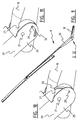
- FIG. 1 through 7 show a preferred variant of a windscreen wiper device 1 according to the invention.
- Said windscreen wiper device is built up of an elastomeric wiper blade 2, in the longitudinal sides of which opposing longitudinal grooves 3 are formed, and of longitudinal strips 4 made of spring band steel, which are fitted in said longitudinal grooves 3.
- Said strips 4 form a flexible carrier element for the rubber wiper blade 2, as it were, which is thus biassed in a curved position (the curvature in operative position being that of a windscreen to be wiped).
- Neighbouring ends 5 of strips 4 are interconnected on either side of the windscreen wiper device 1 by means of connecting pieces 6.
- the windscreen wiper device 1 is further equipped with a connecting device 7 for an oscillating arm 8, and a spoiler 9.
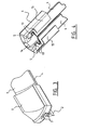
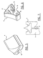
- Figure 2 and 3 show a free end of the windscreen wiper device 1 of figure 1, whereas figure 4 reveals a bottom view of said free end without the wiper blade 2 being present.
- Corresponding parts have been designated with the same reference numerals.
- the connecting piece 6 is provided with an opening 10 in order to allow a relative movement of the wiper blade 2 along the strips 4 inside the connecting piece 6, so that said connecting piece 6 does not block the wiper blade 2 during use.
- the connecting pieces 6 are made of one piece of plastic.
- said strips 4 are each provided with a protrusion 11 extending laterally from a longitudinal interior edge 12 of the strips 4.
- a connecting piece 6 is slidably mounted onto the neighbouring ends 5 of the strips 4, a snap or clicking connection is realized, wherein the protrusions 11 are snapped or clicked between stops 13 ("notches 13") inside the connecting piece 6.
- Each protrusion 11 rests in a small groove 14 between these opposing stops 13. Accordingly, the strips 4 are blocked against any movement in longitudinal direction with respect to the connecting pieces 6.
- Each connecting piece 6 is also provided with two engaging members 15 made integral therewith, wherein said engaging members 15 engage around the strips 4 so as to form a groove 16 for sliding the strips 4 therein. Said engaging members 15 ensure that the strips 4 are blocked against any movement in transversal direction with respect to the connecting pieces 6.
- Each connecting piece 6 has a cavity 17 to accomodate the free end of the spoiler 9.
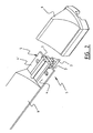
- the windscreen wiper arm 8 comprises a plastic mounting head 18 which can be fixed for rotation to a shaft 19 driven, via a mechanism not illustrated, by a small motor.
- Said windscreen wiper arm 8 further comprises a plastic arm member 20 supported by the mounting head 18, wherein said arm member 20 in turn supports the wiperblade 2 with the help of the connecting device 7, as illustrated in figure 1.
- the arm member 20 is pivotally connected to the mounting head 18 by means of a pivot pin 21.
- a spring 22 is hooked with its first end on a pin 23 on the mounting head 18 and with its second end on to a part 24 of the arm member 20 in order to ensure that the arm member 20 and thus the wiper blade 2 connected thereto is pressed onto a windscreen to be wiped.
- the shaft 19 rotates alternately in a clockwise and in a counterclockwise sense carrying the mounting head 18 into rotation also, which in turn draws the arm member 20 into rotation and by means of the connecting device 7 moves the wiper blade 2.
- the arm member 20 has a substantially U-shaped cross-section near said pivot pin 21 comprising two side walls 25,26, wherein a part of the mounting head 18 extends between the side walls 25,26 and beyond said pivot pin 21. Said part is provided with opposite abutting surfaces 27,28 for abutting against the side walls 25,26.
- a cylindrical protrusion 29 extends laterally inwardly from the side wall 25 into a guiding groove 30 being provided on the abutting surface 27 abutting against the side wall 25.
- the guiding groove has a shape of a part of a circle, for example a quarter of a half of a circle.
- the protrusion 29 is guided by the guiding groove 30 until a maximum pivot angle is reached. In that case, the protrusion 29 is stopped/blocked by a wall of the guiding groove 30, so that the arm member 20 cannot be pivoted vis-à-vis the mounting head 18 beyond said maximum pivot angle.
- a guiding groove may also be provided on the abutting surface 28 cooperating with a cylindrical protrusion extending laterally inwardly from the side wall 26.
- a guiding groove 30 is provided on one or both side wall(s) 25,26, whereas a cylindrical protrusion 29 cooperating therewith is present on one or both abutting surface(s) 27,28 (figure 11).
Landscapes
- Engineering & Computer Science (AREA)
- Mechanical Engineering (AREA)
- Pivots And Pivotal Connections (AREA)
- Body Structure For Vehicles (AREA)
- Transmission Devices (AREA)
Claims (9)
- Bras d'essuie-glace (8), en particulier pour des automobiles, comprenant une tête de montage (18) montable sur un arbre d'entraînement (19) et un élément de bras (20) relié à pivotement à la tête de montage (18) au moyen d'un axe d'articulation (21), dans lequel l'élément de bras (20) possède une section essentiellement en forme de U à proximité dudit axe d'articulation (21) comprenant deux parois latérales (25, 26), dans lequel une partie de la tête de montage (18) s'étend entre les parois latérales (25, 26) et au-delà dudit axe d'articulation (21), caractérisé en ce que des moyens de saillie/rainure (29, 30) sont prévus sur ladite partie de la tête de montage (18) et lesdites parois latérales (25, 26) pour limiter un angle de pivot de l'élément de bras (20), et les moyens de saillie/rainure (29, 30) comprennent au moins une rainure de guidage courbe (30) et au moins une saillie (29) coopérant avec ladite rainure (30).
- Bras d'essuie-glace selon la revendication 1, dans lequel ladite saillie (29) est mobile dans ladite rainure (30) entre une première position correspondant à la position d'essuyage de l'élément de bras (20) et une deuxième position correspondant à une position de montage de l'élément de bras d'essuyage (20).
- Bras d'essuie-glace selon la revendication 1 ou 2, dans lequel ladite partie de la tête de montage (18) est prévue avec des surfaces d'aboutement opposées pour abouter contre les parois latérales (25, 26) de l'élément de bras et dans lequel ladite saillie (29) s'étend latéralement vers l'intérieur à partir d'une des parois latérales (25, 26) dans ladite rainure (30) prévue sur l'une des surfaces d'aboutement aboutant contre cette paroi latérale respective (25, 26).
- Bras d'essuie-glace selon la revendication 1 ou 2, dans lequel ladite partie de la tête de montage (18) est prévue avec des surfaces d'aboutement opposées pour abouter contre les parois latérales (25, 26) de l'élément de bras et dans lequel ladite saillie (29) s'étend latéralement vers l'extérieur à partir de l'une des surfaces d'aboutement dans ladite rainure (30) prévue sur l'une des parois latérales (25, 26) aboutant contre cette surface d'aboutement respective.
- Bras d'essuie-glace selon l'une quelconque des revendications précédentes 1 à 4, dans lequel ladite rainure (30) s'étend le long d'une partie de cercle.
- Bras d'essuie-glace selon l'une quelconque des revendications précédentes 1 à 5, dans lequel l'élément de bras (20) est fait d'un matériau plastique.
- Dispositif d'essuie-glace comprenant un bras d'essuie-glace (8) selon l'une quelconque des revendications précédentes 1 à 6.
- Dispositif d'essuie-glace selon la revendication 7, dans lequel est compris un élément de support allongé élastique, ainsi qu'un balai d'essuie-glace allongé (2) d'un matériau flexible, qui peut être placé en aboutement avec un pare-brise à essuyer, lequel balai d'essuie-glace (2) comprend des rainures longitudinales opposées (3) sur ses côtés longitudinaux, dans lesquelles rainures sont disposées des bandes longitudinales espacées (4) de l'élément de support, dans lequel des extrémités adjacentes (5) desdites bandes longitudinales (4) sont reliées par une pièce de raccord respective (6), lequel dispositif d'essuie-glace comprend un dispositif de raccord (7) pour le bras d'essuie-glace (8) selon l'une quelconque des revendications précédentes 1 à 6.
- Procédé de fabrication d'un bras d'essuie-glace, en particulier pour des automobiles, comprenant une tête de montage (18) montable sur un arbre d'entraînement (19) et un élément de bras (20) relié à pivotement à la tête de montage (18) au moyen d'un axe d'articulation (21), dans lequel l'élément de bras (20) possède une section essentiellement en forme de U à proximité dudit axe d'articulation (21) comprenant deux parois latérales (25, 26), dans lequel une partie de la tête de montage (18) s'étend entre les parois latérales (25, 26) et au-delà de l'axe d'articulation (21), caractérisé en ce que des moyens de saillie/rainure (29, 30) sont prévus sur ladite partie de la tête de montage (18) et lesdites parois latérales (25, 26) pour limiter un angle de pivot de l'élément de bras (20), et les moyens de saillie/rainure (29,30) sont prévus avec au moins une rainure de guidage courbe (30) et au moins une saillie (29) coopérant avec ladite rainure (30).
Priority Applications (9)
| Application Number | Priority Date | Filing Date | Title |
|---|---|---|---|
| DE60314517T DE60314517T2 (de) | 2003-09-11 | 2003-09-11 | Scheibenwischerarm |
| ES03103349T ES2289236T3 (es) | 2003-09-11 | 2003-09-11 | Escobilla limpiaparabrisas. |
| EP03103349A EP1514752B1 (fr) | 2003-09-11 | 2003-09-11 | Bras d'essuie-glace |
| CA002538014A CA2538014A1 (fr) | 2003-09-11 | 2004-09-02 | Bras d'essuie-glace |
| KR1020067004344A KR20060118427A (ko) | 2003-09-11 | 2004-09-02 | 유리창용 와이퍼 암 |
| MXPA06002308A MXPA06002308A (es) | 2003-09-11 | 2004-09-02 | Un brazo para limpiador de parabrisas. |
| JP2006525817A JP2007504995A (ja) | 2003-09-11 | 2004-09-02 | フロントガラスのワイパーアーム |
| PCT/EP2004/052015 WO2005023611A1 (fr) | 2003-09-11 | 2004-09-02 | Bras d'essuie-glace |
| US10/570,799 US20070011840A1 (en) | 2003-09-11 | 2004-09-02 | Windscreen wiper arm |
Applications Claiming Priority (1)
| Application Number | Priority Date | Filing Date | Title |
|---|---|---|---|
| EP03103349A EP1514752B1 (fr) | 2003-09-11 | 2003-09-11 | Bras d'essuie-glace |
Publications (2)
| Publication Number | Publication Date |
|---|---|
| EP1514752A1 EP1514752A1 (fr) | 2005-03-16 |
| EP1514752B1 true EP1514752B1 (fr) | 2007-06-20 |
Family
ID=34130327
Family Applications (1)
| Application Number | Title | Priority Date | Filing Date |
|---|---|---|---|
| EP03103349A Expired - Fee Related EP1514752B1 (fr) | 2003-09-11 | 2003-09-11 | Bras d'essuie-glace |
Country Status (9)
| Country | Link |
|---|---|
| US (1) | US20070011840A1 (fr) |
| EP (1) | EP1514752B1 (fr) |
| JP (1) | JP2007504995A (fr) |
| KR (1) | KR20060118427A (fr) |
| CA (1) | CA2538014A1 (fr) |
| DE (1) | DE60314517T2 (fr) |
| ES (1) | ES2289236T3 (fr) |
| MX (1) | MXPA06002308A (fr) |
| WO (1) | WO2005023611A1 (fr) |
Families Citing this family (29)
| Publication number | Priority date | Publication date | Assignee | Title |
|---|---|---|---|---|
| CA2514372A1 (fr) * | 2004-07-30 | 2006-01-30 | M Management-Tex, Ltd. | Structure de balai d'essuie-glace |
| TR200804766U (tr) * | 2006-04-21 | 2008-09-22 | Teklas Kauçuk Sanayi̇ Ve Ti̇caret A.Ş. | Bir taşıt sileceği |
| EP2045153B1 (fr) * | 2007-10-01 | 2014-11-26 | Federal-Mogul S.A. | Dispositif d'essuie-glace |
| DE102008000708A1 (de) * | 2008-03-17 | 2009-09-24 | Robert Bosch Gmbh | Wischblatt |
| ES2387698T3 (es) * | 2008-03-19 | 2012-09-28 | Federal-Mogul S.A. | Dispositivo de limpiaparabrisas |
| ES2379023T3 (es) | 2008-07-11 | 2012-04-20 | Federal-Mogul S.A. | Un dispositivo de limpiaparabrisas |
| ES2408185T3 (es) * | 2008-08-26 | 2013-06-18 | Federal-Mogul S.A. | Dispositivo de limpiaparabrisas |
| PL2421729T5 (pl) | 2009-04-24 | 2018-05-30 | Federal-Mogul S.A. | Urządzenie wycieraczki przedniej szyby |
| CN102917923B (zh) | 2010-04-22 | 2016-02-17 | 联邦莫古尔股份有限公司 | 挡风玻璃刮水器装置 |
| US8495787B2 (en) | 2010-08-03 | 2013-07-30 | Rally Manufacturing, Inc. | Windshield wiper |
| US8857009B2 (en) * | 2010-11-24 | 2014-10-14 | Trico Products Corporation | Beam blade wiper assembly having self-locking end cap |
| DE202011100908U1 (de) | 2011-05-19 | 2011-10-27 | Federal-Mogul S.A. | Abnehmbarer Abstandshalter und Scheibenwischer |
| CN103101514B (zh) * | 2011-09-15 | 2016-09-07 | 阿斯莫有限公司 | 车辆擦拭器 |
| US9174610B2 (en) | 2011-09-15 | 2015-11-03 | Asmo Co., Ltd. | Wiper blade and wiper for vehicle |
| CA2857062A1 (fr) * | 2011-12-14 | 2013-06-20 | Federal-Mogul S.A. | Dispositif d'essuie-glace |
| WO2013149676A1 (fr) * | 2012-04-05 | 2013-10-10 | Federal-Mogul S.A. | Bras d'essuie-glace de pare-brise et procédé pour sa production |
| US10189444B2 (en) | 2012-06-21 | 2019-01-29 | Federal-Mogul S.A. | Windscreen wiper arm |
| KR101212283B1 (ko) * | 2012-10-25 | 2012-12-13 | 동양기전 주식회사 | 엔드 캡 구조가 개선된 플랫 블레이드 타입 와이퍼 장치 |
| KR101276575B1 (ko) * | 2012-12-28 | 2013-06-18 | 동양기전 주식회사 | 록 백 구조가 개선된 와이퍼 암 장치 |
| DE102013217985A1 (de) * | 2013-09-09 | 2015-03-26 | Robert Bosch Gmbh | Befestigungsvorrichtung für eine Scheibenwischvorrichtung |
| DE102013222994A1 (de) * | 2013-11-12 | 2015-05-28 | Robert Bosch Gmbh | Scheibenwischvorrichtung |
| DE102014214580A1 (de) * | 2014-07-24 | 2016-01-28 | Robert Bosch Gmbh | Befestigungsvorrichtung für eine Scheibenwischvorrichtung |
| US9604598B2 (en) * | 2015-07-09 | 2017-03-28 | GM Global Technology Operations LLC | Wiper arm pin release for service |
| EP3416858B1 (fr) * | 2016-02-15 | 2021-10-06 | Federal-Mogul S.a. | Dispositif d'essuie-glace |
| US11577699B2 (en) | 2018-09-18 | 2023-02-14 | Trico Belgium S.a. | Windscreen wiper device |
| WO2020239224A1 (fr) | 2019-05-29 | 2020-12-03 | Trico Belgium S.a. | Bras d'essuie-glace |
| WO2020239222A1 (fr) | 2019-05-29 | 2020-12-03 | Trico Belgium S.a. | Bras d'essuie-glace |
| EP4045366B1 (fr) | 2019-10-15 | 2024-03-20 | Trico Belgium S.A. | Bras d'essuie-glace de pare-brise |
| WO2023284956A1 (fr) | 2021-07-14 | 2023-01-19 | Trico Belgium S.a. | Bras d'essuie-glace |
Family Cites Families (12)
| Publication number | Priority date | Publication date | Assignee | Title |
|---|---|---|---|---|
| US3427676A (en) * | 1968-01-12 | 1969-02-18 | Trico Products Corp | Windshield wiper arm |
| DE3433106C2 (de) * | 1984-09-08 | 1986-08-14 | SWF Auto-Electric GmbH, 7120 Bietigheim-Bissingen | Wischarm, insbesondere für Wischanlagen an Kraftfahrzeugen |
| FR2629032B1 (fr) * | 1988-03-25 | 1991-10-04 | Peugeot | Dispositif d'essuie-glace dissimulable destine a equiper, par exemple, un vehicule automobile |
| US4984325A (en) * | 1988-11-15 | 1991-01-15 | Nippon Wiperblade Co., Ltd. | Windshield wiper |
| FR2667556B1 (fr) * | 1990-10-03 | 1993-07-02 | Valeo Systemes Dessuyage | Bras d'essuie-glace notamment pour vehicule automobile. |
| FR2692216B1 (fr) * | 1992-06-16 | 1998-06-12 | Valeo Systemes Dessuyage | Dispositif d'essuie-glace a capuchon articule sur la tige d'accrochage du ressort. |
| FR2736024B1 (fr) | 1995-06-28 | 1997-08-08 | Valeo Systemes Dessuyage | Essuie-glace de vehicule automobile muni de moyens de limitation du soulevement du bras d'essuie-glace |
| DE19739256A1 (de) * | 1997-09-08 | 1999-03-11 | Bosch Gmbh Robert | Wischblatt zum Reinigen von Scheiben von Kraftfahrzeugen |
| DE19856300A1 (de) * | 1998-12-07 | 2000-06-08 | Bosch Gmbh Robert | Wischblatt für Scheiben von Kraftfahrzeugen |
| JP2000203391A (ja) * | 1999-01-11 | 2000-07-25 | Asmo Co Ltd | 部材の支持構造 |
| DE19951440B4 (de) * | 1999-10-25 | 2015-04-02 | Robert Bosch Gmbh | Wischarm für ein Fahrzeug |
| DE19951363A1 (de) * | 1999-10-26 | 2001-05-03 | Bosch Gmbh Robert | Wischblatt für Scheiben von Kraftfahrzeugen |
-
2003
- 2003-09-11 DE DE60314517T patent/DE60314517T2/de not_active Expired - Lifetime
- 2003-09-11 EP EP03103349A patent/EP1514752B1/fr not_active Expired - Fee Related
- 2003-09-11 ES ES03103349T patent/ES2289236T3/es not_active Expired - Lifetime
-
2004
- 2004-09-02 US US10/570,799 patent/US20070011840A1/en not_active Abandoned
- 2004-09-02 CA CA002538014A patent/CA2538014A1/fr not_active Abandoned
- 2004-09-02 JP JP2006525817A patent/JP2007504995A/ja active Pending
- 2004-09-02 KR KR1020067004344A patent/KR20060118427A/ko not_active Application Discontinuation
- 2004-09-02 WO PCT/EP2004/052015 patent/WO2005023611A1/fr active Application Filing
- 2004-09-02 MX MXPA06002308A patent/MXPA06002308A/es active IP Right Grant
Also Published As
| Publication number | Publication date |
|---|---|
| MXPA06002308A (es) | 2006-05-19 |
| EP1514752A1 (fr) | 2005-03-16 |
| JP2007504995A (ja) | 2007-03-08 |
| US20070011840A1 (en) | 2007-01-18 |
| DE60314517T2 (de) | 2008-02-07 |
| CA2538014A1 (fr) | 2005-03-17 |
| ES2289236T3 (es) | 2008-02-01 |
| KR20060118427A (ko) | 2006-11-23 |
| WO2005023611A1 (fr) | 2005-03-17 |
| DE60314517D1 (de) | 2007-08-02 |
Similar Documents
| Publication | Publication Date | Title |
|---|---|---|
| EP1514752B1 (fr) | Bras d'essuie-glace | |
| EP2421729B2 (fr) | Dispositif d'essuie-glace | |
| EP3416858B1 (fr) | Dispositif d'essuie-glace | |
| EP2143602B2 (fr) | Dispositif d'essuie-glace | |
| EP2834111B1 (fr) | Bras d'essuie-glace de pare-brise et procédé pour sa production | |
| EP3019373B1 (fr) | Appareil d'essuie glace | |
| EP2790970B1 (fr) | Balai d'essuie-glace | |
| US20070261192A1 (en) | Windscreen Wiper Arm | |
| EP1810898A1 (fr) | Bras d'essuie-glace | |
| EP2864161B1 (fr) | Bras d'essuie-glace | |
| EP3853083B1 (fr) | Dispositif d'essuie-glace | |
| WO2011026507A1 (fr) | Dispositif d'essuie-glace pour pare-brise | |
| US20080184516A1 (en) | Windscreen Wiper Arm |
Legal Events
| Date | Code | Title | Description |
|---|---|---|---|
| PUAI | Public reference made under article 153(3) epc to a published international application that has entered the european phase |
Free format text: ORIGINAL CODE: 0009012 |
|
| AK | Designated contracting states |
Kind code of ref document: A1 Designated state(s): AT BE BG CH CY CZ DE DK EE ES FI FR GB GR HU IE IT LI LU MC NL PT RO SE SI SK TR |
|
| AX | Request for extension of the european patent |
Extension state: AL LT LV MK |
|
| 17P | Request for examination filed |
Effective date: 20050906 |
|
| AKX | Designation fees paid |
Designated state(s): BE DE ES FR GB IT |
|
| GRAP | Despatch of communication of intention to grant a patent |
Free format text: ORIGINAL CODE: EPIDOSNIGR1 |
|
| GRAS | Grant fee paid |
Free format text: ORIGINAL CODE: EPIDOSNIGR3 |
|
| GRAA | (expected) grant |
Free format text: ORIGINAL CODE: 0009210 |
|
| AK | Designated contracting states |
Kind code of ref document: B1 Designated state(s): BE DE ES FR GB IT |
|
| REG | Reference to a national code |
Ref country code: GB Ref legal event code: FG4D |
|
| REF | Corresponds to: |
Ref document number: 60314517 Country of ref document: DE Date of ref document: 20070802 Kind code of ref document: P |
|
| ET | Fr: translation filed | ||
| REG | Reference to a national code |
Ref country code: ES Ref legal event code: FG2A Ref document number: 2289236 Country of ref document: ES Kind code of ref document: T3 |
|
| PLBE | No opposition filed within time limit |
Free format text: ORIGINAL CODE: 0009261 |
|
| STAA | Information on the status of an ep patent application or granted ep patent |
Free format text: STATUS: NO OPPOSITION FILED WITHIN TIME LIMIT |
|
| 26N | No opposition filed |
Effective date: 20080325 |
|
| PGFP | Annual fee paid to national office [announced via postgrant information from national office to epo] |
Ref country code: ES Payment date: 20090911 Year of fee payment: 7 |
|
| PGFP | Annual fee paid to national office [announced via postgrant information from national office to epo] |
Ref country code: GB Payment date: 20090807 Year of fee payment: 7 |
|
| PGFP | Annual fee paid to national office [announced via postgrant information from national office to epo] |
Ref country code: IT Payment date: 20090918 Year of fee payment: 7 |
|
| PGFP | Annual fee paid to national office [announced via postgrant information from national office to epo] |
Ref country code: BE Payment date: 20091022 Year of fee payment: 7 |
|
| BERE | Be: lapsed |
Owner name: FEDERAL-MOGUL S.A. Effective date: 20100930 |
|
| GBPC | Gb: european patent ceased through non-payment of renewal fee |
Effective date: 20100911 |
|
| PG25 | Lapsed in a contracting state [announced via postgrant information from national office to epo] |
Ref country code: IT Free format text: LAPSE BECAUSE OF NON-PAYMENT OF DUE FEES Effective date: 20100911 |
|
| PG25 | Lapsed in a contracting state [announced via postgrant information from national office to epo] |
Ref country code: BE Free format text: LAPSE BECAUSE OF NON-PAYMENT OF DUE FEES Effective date: 20100930 |
|
| PG25 | Lapsed in a contracting state [announced via postgrant information from national office to epo] |
Ref country code: GB Free format text: LAPSE BECAUSE OF NON-PAYMENT OF DUE FEES Effective date: 20100911 |
|
| REG | Reference to a national code |
Ref country code: ES Ref legal event code: FD2A Effective date: 20111019 |
|
| PG25 | Lapsed in a contracting state [announced via postgrant information from national office to epo] |
Ref country code: ES Free format text: LAPSE BECAUSE OF NON-PAYMENT OF DUE FEES Effective date: 20100912 |
|
| REG | Reference to a national code |
Ref country code: FR Ref legal event code: PLFP Year of fee payment: 14 |
|
| PGFP | Annual fee paid to national office [announced via postgrant information from national office to epo] |
Ref country code: FR Payment date: 20160817 Year of fee payment: 14 |
|
| PGFP | Annual fee paid to national office [announced via postgrant information from national office to epo] |
Ref country code: DE Payment date: 20160928 Year of fee payment: 14 |
|
| REG | Reference to a national code |
Ref country code: DE Ref legal event code: R119 Ref document number: 60314517 Country of ref document: DE |
|
| REG | Reference to a national code |
Ref country code: FR Ref legal event code: ST Effective date: 20180531 |
|
| PG25 | Lapsed in a contracting state [announced via postgrant information from national office to epo] |
Ref country code: DE Free format text: LAPSE BECAUSE OF NON-PAYMENT OF DUE FEES Effective date: 20180404 |
|
| PG25 | Lapsed in a contracting state [announced via postgrant information from national office to epo] |
Ref country code: FR Free format text: LAPSE BECAUSE OF NON-PAYMENT OF DUE FEES Effective date: 20171002 |