EP2421729B2 - Dispositif d'essuie-glace - Google Patents
Dispositif d'essuie-glace Download PDFInfo
- Publication number
- EP2421729B2 EP2421729B2 EP09779356.6A EP09779356A EP2421729B2 EP 2421729 B2 EP2421729 B2 EP 2421729B2 EP 09779356 A EP09779356 A EP 09779356A EP 2421729 B2 EP2421729 B2 EP 2421729B2
- Authority
- EP
- European Patent Office
- Prior art keywords
- mounting head
- connecting device
- windscreen wiper
- wiper blade
- windscreen
- Prior art date
- Legal status (The legal status is an assumption and is not a legal conclusion. Google has not performed a legal analysis and makes no representation as to the accuracy of the status listed.)
- Active
Links
Images


Classifications
-
- B—PERFORMING OPERATIONS; TRANSPORTING
- B60—VEHICLES IN GENERAL
- B60S—SERVICING, CLEANING, REPAIRING, SUPPORTING, LIFTING, OR MANOEUVRING OF VEHICLES, NOT OTHERWISE PROVIDED FOR
- B60S1/00—Cleaning of vehicles
- B60S1/02—Cleaning windscreens, windows or optical devices
- B60S1/56—Cleaning windscreens, windows or optical devices specially adapted for cleaning other parts or devices than front windows or windscreens
- B60S1/58—Cleaning windscreens, windows or optical devices specially adapted for cleaning other parts or devices than front windows or windscreens for rear windows
- B60S1/583—Cleaning windscreens, windows or optical devices specially adapted for cleaning other parts or devices than front windows or windscreens for rear windows including wiping devices
-
- B—PERFORMING OPERATIONS; TRANSPORTING
- B60—VEHICLES IN GENERAL
- B60S—SERVICING, CLEANING, REPAIRING, SUPPORTING, LIFTING, OR MANOEUVRING OF VEHICLES, NOT OTHERWISE PROVIDED FOR
- B60S1/00—Cleaning of vehicles
- B60S1/02—Cleaning windscreens, windows or optical devices
- B60S1/04—Wipers or the like, e.g. scrapers
- B60S1/32—Wipers or the like, e.g. scrapers characterised by constructional features of wiper blade arms or blades
- B60S1/34—Wiper arms; Mountings therefor
- B60S1/3425—Constructional aspects of the arm
- B60S1/3445—Joints between elements
- B60S1/345—Joints between elements the elements being a link piece and a mounting head
-
- B—PERFORMING OPERATIONS; TRANSPORTING
- B60—VEHICLES IN GENERAL
- B60S—SERVICING, CLEANING, REPAIRING, SUPPORTING, LIFTING, OR MANOEUVRING OF VEHICLES, NOT OTHERWISE PROVIDED FOR
- B60S1/00—Cleaning of vehicles
- B60S1/02—Cleaning windscreens, windows or optical devices
- B60S1/04—Wipers or the like, e.g. scrapers
- B60S1/32—Wipers or the like, e.g. scrapers characterised by constructional features of wiper blade arms or blades
- B60S1/38—Wiper blades
- B60S1/3848—Flat-type wiper blade, i.e. without harness
- B60S1/3849—Connectors therefor; Connection to wiper arm; Attached to blade
-
- B—PERFORMING OPERATIONS; TRANSPORTING
- B60—VEHICLES IN GENERAL
- B60S—SERVICING, CLEANING, REPAIRING, SUPPORTING, LIFTING, OR MANOEUVRING OF VEHICLES, NOT OTHERWISE PROVIDED FOR
- B60S1/00—Cleaning of vehicles
- B60S1/02—Cleaning windscreens, windows or optical devices
- B60S1/04—Wipers or the like, e.g. scrapers
- B60S1/32—Wipers or the like, e.g. scrapers characterised by constructional features of wiper blade arms or blades
- B60S1/34—Wiper arms; Mountings therefor
- B60S1/3425—Constructional aspects of the arm
- B60S1/3436—Mounting heads
-
- B—PERFORMING OPERATIONS; TRANSPORTING
- B60—VEHICLES IN GENERAL
- B60S—SERVICING, CLEANING, REPAIRING, SUPPORTING, LIFTING, OR MANOEUVRING OF VEHICLES, NOT OTHERWISE PROVIDED FOR
- B60S1/00—Cleaning of vehicles
- B60S1/02—Cleaning windscreens, windows or optical devices
- B60S1/04—Wipers or the like, e.g. scrapers
- B60S1/32—Wipers or the like, e.g. scrapers characterised by constructional features of wiper blade arms or blades
- B60S1/38—Wiper blades
- B60S2001/3812—Means of supporting or holding the squeegee or blade rubber
- B60S2001/3825—Means of supporting or holding the squeegee or blade rubber the squeegee mounted directly to or in wiper blade arm
Definitions
- the invention relates to a windscreen wiper device, particularly for automobiles, comprising an elastic, elongated carrier element, as well as an elongated wiper blade of a flexible material, which can be placed in abutment with a windscreen to be wiped, which wiper blade is of the flat blade type and includes at least one groove, in which groove a longitudinal strip of the carrier element is disposed, wherein said windscreen wiper device further comprises a mounting head for transferring a reciprocal movement to said wiper blade.
- windscreen wiper device is known from European patent publication no. 1 514 752 (Federal-Mogul S.A.).
- the windscreen wiper device described in this European patent publication comprises a mounting head mountable on a drive shaft and an arm member pivotally connected to the mounting head by means of a pivot pin, wherein the arm member has a substantially U-shaped cross-section near said pivot pin comprising two side walls, wherein a part of the mounting head extends between the side walls and beyond said pivot pin.
- a disadvantage of the windscreen wiper arm known from the above European patent publication is that it comprises many complex parts with a dedicated shape, wherein reference is made to the oscillating arm described therein consisting of a plastic arm member at one end thereof pivotally connected to a mounting head by means of a pivot pin and at the other end thereof folded around a rod-like part. Obviously, this needs complex machinery, tools, with all the expenses involved.
- the gist of the present invention is to refrain from the use of an intermediate oscillating arm, thereby avoiding an articulation between the oscillating arm and the wiper blade, as well as between the mounting head and the oscillating arm. This not only ensures that less parts have to be used in manufacturing said windscreen wiper device with all advantages involved (such as cheaper, lighter, less plastic material sensitive to UV-light), but also that disadvantages like wear are obviated. Further, by directly connecting said connecting device to the mounting head, said wiper blade is mounted closer to the windscreen to be wiped, so that the wiping properties are improved. Also, by locating the connecting device in its entirety inside said mounting head, a very strong connection between is formed that can withstand large torque.
- said connecting device and said connecting piece are connected to said wiper blade at opposite ends thereof.
- United States patent publication no. 2008/0209662 (Wilms et al. ) relates to a windscreen wiper arm comprising a wiper bar, to which a wiper blade can be attached with or without a spoiler.
- Said bar is composed of a freely projecting, first arc-shaped wiper bar section with a first curvature variation, to which the wiper blade is attached and of at least one second arc-shaped wiper bar section with a second arc-shaped curvature variation, which adjoins the first wiper bar section, to form a snap- off point.
- DE 10040129 A1 corresponds to the preamble of claim 1.
- DE 100 40 129 11 corresponds to the preamble of claim 1.
- Said connecting device and said mounting head are each preferably made of one piece.
- the present windscreen wiper device is particularly designed for use at a rear window of a car.
- said wiper blade includes opposing longitudinal grooves on its longitudinal sides, in which grooves spaced-apart longitudinal strips of the carrier element are disposed, wherein neighbouring ends of said longitudinal strips are interconnected by said connecting device at one end of said wiper blade and by said connecting piece at the other end of said wiper blade.
- Said connecting device may be glued, soldered, clipped, snapped or welded onto said longitudinal strips.
- said mounting head has an at least substantially U-shaped cross-section at the location of its attachment to said connecting device wherein said engaging members comprise legs of said U-shaped cross-section, and wherein each leg at the free end thereof comprises inwardly bended edges engaging around said bottom of said connecting device.
- said mounting head has an at least substantially 0-shaped cross-section at the location of its attachment to said connecting device, wherein said engaging members comprise sides of said 0-shaped cross-section.
- said strip and said connecting device are slidably connected by means of a snap connection.
- said snap connecting comprises at least one protrusion extending laterally from a longitudinal edge of said strip, said protrusion being located between stops on the connecting device, and/or
- said snap connecting comprises at least two stops extending laterally from a longitudinal edge of said strip, said stops being located on opposite sides of a protrusion on the connecting device.
- said protrusion and/or said stops of said strip extend laterally from the interior or exterior edge of said strip.
- said longitudinal strip is biassed in such a way that its curvature radius near the connecting device is smaller than that its curvature radius near the other end of said wiper blade, all seen in dismounted position.
- said wiper blade in dismounted position said wiper blade has an asymmetric shape, seen along its middle transverse plane perpendicular to a windscreen to be wiped.
- said wiper blade is able to follow any curvature of a windscreen to be wiped, while said wiper blade is pressed onto said windscreen to be wiper with sufficient force to enhance the wiping properties.
- the interconnection between the mounting head and the wiper blade does not allow any pivotal movement.
- said mounting head and said connecting device cannot move relative to one another, i.e. are stationary with respect to each other.
- said mounting head is fixed for rotation to a shaft, wherein said shaft is rotatable alternately in a clockwise and in a counter-clockwise sense carrying said mounting head into rotation.
- said mounting head draws said connecting device into rotation and thereby moves said wiper blade.
- said mounting head is fixed for translation to a carriage, wherein said carriage can be translated alternately in a one linear direction and in another counter linear direction carrying said mounting head into translation.
- the present invention can therefore be used for circular or linear movement of said mounting head.
- said connecting device comprises at least one resilient tongue engaging in a correspondingly shaped hole provided said mounting head, and wherein said resilient tongue is movable between a outward position retaining said connecting device and the wiper blade onto said mounting head and an inward position releasing said connecting device and the wiper blade from said mounting head.
- said resilient tongue is initially pushed in against a spring force - as if it were a push button - and then allowed to spring back into the hole provided in said mounting head, thus snapping, that is clipping the resilient tongue into the hole.
- said hole has a closed circumference.
- said resilient tongue is hingeable along an hinge axis, wherein the hinge axis is orientated towards said mounting head (so that said resilient tongue opens away from said mounting head) or facing away from said mounting head near an outer edge of said joint part (so that said resilient tongue opens towards said mounting head).
- said hinge axis is located at an outer edge of said connecting device.
- said hole is provided in a base of the U-shaped or O-shaped cross-section of said mounting head.
- said resilient tongue may be provided on an upper part of said connecting device.
- the connecting device may be provided with at least two lateral resilient tongues extending outwardly, wherein each tongue engages in a correspondingly shaped hole provided in each leg of the U-shaped or O-shaped cross-section of said mounting head.
- Said holes preferably have a closed circumference. Such closed holes enhance the retention of the connection device onto the mounting head in all possible directions, particularly both horizontally and vertically.
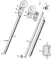
- the windscreen wiper device 1 is built up of an elastomeric wiper blade 2, in the longitudinal sides of which opposing longitudinal grooves 3 are formed, and of longitudinal strips 4 made of spring band steel, which are fitted in said longitudinal grooves 3. Said strips 4 form a flexible carrier element for the wiper blade 2, as it were, which is thus biassed in a curved position (the curvature in operative position being that of a windscreen to be wiped). Neighbouring ends 5 of the strips 4 at one end of said wiper blade 2 are interconnected by means of a connecting piece 6 or "end cap" functioning as clamping member.
- the connecting piece 6 is a separate constructional element, which may be form-locked ("positive locking” or “having a positive fit") or force-locked to the ends 5 of the strips 4.
- said connecting piece 6 is in one piece with the strips 4 made of spring band steel. In the latter case said connecting piece 6 forms a transverse bridge for the strips 4, as it were.
- the windscreen wiper device 1 is furthermore built up of a connecting device 7 of plastic material for a mounting head 8.
- the connecting device 7 may also be made of metal, such as steel or aluminum.
- the connecting device 7 is connected to said wiper blade 2 at its other end, that is opposite the connecting piece 6.
- the connecting device 7 engages around strips 4 and comprises protrusions or stops 9 extending from the connecting device 7 in the direction of the bottom part of the connecting device 7, which is the part facing the windscreen (not shown).
- Strips 4 comprise protrusions or stops 10, extending laterally from a longitudinal edge of strips 4. In figure 1 , the protrusions or stops 10 extend laterally from the exterior edge of strips 4, but they can also extend from the interior edge.
- Strips 4 are slidably connected to the connecting device by means of a snap connection formed by the protrusions/stops 9 of the connecting device 7 and protrusions/stops 10 of strips 4, wherein the protrusions 10A of the strips 4 extend between the stops 9 of the connecting device 7, and wherein the stops 10 of the strips 4 extend around the protrusions 9A of the connecting device 7.
- the connecting device 7 is firmly attached to the unit consisting of the wiper blade 2 and the strips 4.
- the windscreen wiper device 1 comprises a plastic or metallic mounting head 8 which can be fixed for rotation to a shaft 11 driven, via a mechanism not illustrated, by a small motor.
- the shaft 11 rotates alternately in a clockwise and in a counter-clockwise sense carrying the mounting head 8 into rotation also, which in turn draws the connecting device 7 in rotation and thereby moves the wiper blade 2.
- the connecting device 7 comprises one resilient tongue 12 extending outwardly, while the mounting head 8 has an U-shaped ( figure 2a ) or 0-shaped ( figure 2b ) cross-section at the location of its connection to said connecting device 7, so that the tongue 12 engages in an identically shaped hole 13 provided in a base 14 of said U/O-shaped cross-section.
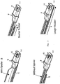
- FIG 3 shows the steps of mounting the connecting device 7 with the wiper blade 2 onto the mounting head 8.
- the connecting device 7 can be easily slid in horizontal direction on a free end of the mounting head 8.
- the resilient tongue 12 is initially pushed in against a spring force and then allowed to spring back into said hole 13, thus snapping, that is clipping the resilient tongue 12 into the hole 13.
- This is a so-called bayonet-connection.
- the mounting head 8 together with the connecting device 7 are then ready for use.
- Figure 2a shows that the U-shaped cross-section is formed by engaging members of the mounting head 8, which comprise legs 15 and inwardly bended edges 16 integral with said legs 15, wherein during use said legs 15 engage around longitudinal sides of said connecting device 7 that face away from each other and said inwardly bended edges 16 engage around the bottom part of said connecting device 7 that faces the windscreen (not shown).
- the bottom part can also be identified as the part facing away from the part of the connecting device 7 that comprises the resilient tongue 12.
- a U-shaped cross-section of the mounting head 8 it can be an 0-shaped cross-section, as seen in figure 2b , wherein engagement members engage totally around said longitudinal sides and said bottom part and wherein the engagement members thus form sides of the 0-shape.
- a very strong connection that can withstand large torque is formed between the mounting head 8 and the connecting device 7, due to that the connecting device 7 at the location of its attachment to the mounting head 8 is in its entirety located in the mounting head 8, because of the engaging members of the mounting head 8 engaging around longitudinal sides and the bottom part of the connecting device 7.
- Figure 4 shows another embodiment of a windscreen wiper device 1 according to the invention, wherein a central longitudinal groove 3 is formed in the wiper blade 2, in which a single longitudinal strip 4 is fitted.
- FIG 5 relates to several views of the wiper blade 2 of figures 1 , 2 and 3 .
- said wiper blade 2 may be equipped with or without a spoiler 17 ( figures 5a and 5b ), while the wiper blade 2 as such may or may not extend under said connecting device 7 ( figures 5c and 5d ).
Claims (10)
- Dispositif d'essuie-glace (1), en particulier pour automobiles, comprenant un élément de support allongé élastique, ainsi qu'un balai d'essuie-glace allongé (2) en matériau flexible, qui peut être placé en butée avec un pare-brise à essuyer, lequel balai d'essuie-glace (2) est du type balai plat et comprend au moins une rainure (3), dans laquelle rainure (3), est disposée une bande longitudinale (4) de l'élément de support, dans lequel ledit dispositif d'essuie-glace (1) comprend en outre une tête de montage (8) pour transférer un mouvement de va-et-vient audit balai d'essuie-glace (2), dans lequel ledit dispositif d'essuie-glace (1) comprend en outre un dispositif de raccordement (7) pour raccorder, de manière détachable, ledit balai d'essuie-glace (2) directement à ladite tête de montage (8), dans lequel ledit dispositif de raccordement (7) est positionné à proximité d'une extrémité dudit balai d'essuie-glace (2), et dans lequel ledit dispositif de raccordement (7), à l'emplacement de sa fixation sur ladite tête de montage (8), est positionné dans son intégralité, à l'intérieur de ladite tête de montage (8), dans lequel ladite tête de montage (8), à l'emplacement de sa fixation audit dispositif de raccordement (7), comprend des éléments de mise en prise se mettant en prise autour des côtés longitudinaux et autour d'un fond dudit dispositif de raccordement (7), de sorte que ledit dispositif de raccordement (7) est monté dans un canal formé par lesdits éléments de mise en prise, dans lequel ladite bande (4) et ledit dispositif de raccordement (7) sont raccordés, de manière coulissante, au moyen d'un raccordement par encliquetage, dans lequel ledit dispositif de raccordement par encliquetage comprend au moins une saillie (10a) s'étendant latéralement à partir d'un bord longitudinal de ladite bande (4), ladite saillie étant positionnée entre des butées (9) sur le dispositif de raccordement (7), et/ou dans lequel ledit dispositif de raccordement par encliquetage comprend au moins deux butées (10) s'étendant latéralement à partir d'un bord longitudinal de ladite bande, lesdites butées étant positionnées sur les côtés opposés d'une saillie (9a) sur le dispositif de raccordement, dans lequel ledit dispositif de raccordement (7) comprend au moins une languette résiliente (12) se mettant en prise dans un trou formé de manière correspondante (13) prévu dans ladite tête de montage (8), caractérisé en ce que ladite languette résiliente (12) est mobile entre une position vers l'extérieur retenant ledit dispositif de raccordement (7) conjointement avec le balai d'essuie-glace (2) sur ladite tête de montage (8) et une position vers l'intérieur libérant ledit dispositif de raccordement (7) conjointement avec le balai d'essuie-glace (2) de ladite tête de montage (8).
- Dispositif d'essuie-glace (1) selon la revendication 1, dans lequel ladite tête de montage (8) a une section transversale au moins sensiblement en forme de U à l'emplacement de sa fixation avec ledit dispositif de raccordement (7), dans lequel lesdits éléments de mise en prise comprennent des pattes (15) de ladite section transversale en forme de U, et dans lequel chaque patte (15), au niveau de son extrémité libre, comprend des bords pliés vers l'intérieur (16) se mettant en prise autour dudit fond dudit élément de raccordement (7).
- Dispositif d'essuie-glace (1) selon la revendication 1, dans lequel ladite tête de montage (8) a une section transversale au moins sensiblement en forme de O à l'emplacement de sa fixation avec ledit dispositif de raccordement (7), dans lequel lesdits éléments de mise en prise comprennent des côtés de ladite section transversale en forme de O.
- Dispositif d'essuie-glace (1) selon la revendication 1, 2 ou 3 dans lequel ladite saillie et/ou lesdites butées (10) de ladite bande (4) s'étendent latéralement à partir du bord intérieur ou extérieur de ladite bande (4).
- Dispositif d'essuie-glace (1) selon l'une quelconque des revendications 1 à 4, dans lequel ledit dispositif d'essuie-glace (1) comprend en outre une pièce de raccordement (6) positionnée à proximité de l'autre extrémité dudit balai d'essuie-glace (2) et raccordée à une extrémité de ladite bande longitudinale (4).
- Dispositif d'essuie-glace (1) selon l'une quelconque des revendications 1 à 5, dans lequel ladite bande longitudinale (4) est sollicitée de sorte que sa courbure, à proximité du dispositif de raccordement (7), est plus importante que sa courbure à proximité de l'autre extrémité dudit balai d'essuie-glace (2).
- Dispositif d'essuie-glace (1) selon l'une quelconque des revendications 1 à 6, dans lequel l'interconnexion entre la tête de montage (8) et le balai d'essuie-glace (2) ne permet pas de mouvement pivotant.
- Dispositif d'essuie-glace (1) selon l'une quelconque des revendications 1 à 7, dans lequel ladite tête de montage (8) est fixée, pour la rotation, à un arbre (9), et dans lequel ledit arbre (9) peut tourner de manière alternée dans le sens des aiguilles d'une montre et dans le sens inverse des aiguilles d'une montre portant ladite tête de montage (8) en rotation.
- Dispositif d'essuie-glace (1) selon l'une quelconque des revendications 1 à 8, dans lequel ladite tête de montage (8) est fixée, pour la translation, à un chariot, et dans lequel ledit chariot peut effectuer un mouvement de translation de manière alternée dans une direction linéaire et dans une autre direction linéaire opposée portant ladite tête de montage (8) en translation.
- Dispositif d'essuie-glace (1) selon l'une quelconque des revendications précédentes, dans lequel ledit trou (13) est prévu dans une base (14) de la section transversale en forme de U ou en forme de O de ladite tête de montage (8).
Priority Applications (2)
| Application Number | Priority Date | Filing Date | Title |
|---|---|---|---|
| PL09779356T PL2421729T5 (pl) | 2009-04-24 | 2009-04-24 | Urządzenie wycieraczki przedniej szyby |
| SI200930937T SI2421729T1 (sl) | 2009-04-24 | 2009-04-24 | Brisalna priprava za vetrobransko steklo |
Applications Claiming Priority (1)
| Application Number | Priority Date | Filing Date | Title |
|---|---|---|---|
| PCT/EP2009/055007 WO2010121665A1 (fr) | 2009-04-24 | 2009-04-24 | Dispositif d'essuie-glace |
Publications (3)
| Publication Number | Publication Date |
|---|---|
| EP2421729A1 EP2421729A1 (fr) | 2012-02-29 |
| EP2421729B1 EP2421729B1 (fr) | 2014-03-05 |
| EP2421729B2 true EP2421729B2 (fr) | 2017-11-08 |
Family
ID=41328619
Family Applications (1)
| Application Number | Title | Priority Date | Filing Date |
|---|---|---|---|
| EP09779356.6A Active EP2421729B2 (fr) | 2009-04-24 | 2009-04-24 | Dispositif d'essuie-glace |
Country Status (9)
| Country | Link |
|---|---|
| US (1) | US20120036671A1 (fr) |
| EP (1) | EP2421729B2 (fr) |
| JP (1) | JP5444454B2 (fr) |
| KR (1) | KR101592626B1 (fr) |
| CN (1) | CN102427973B (fr) |
| ES (1) | ES2469866T3 (fr) |
| PL (1) | PL2421729T5 (fr) |
| SI (1) | SI2421729T1 (fr) |
| WO (1) | WO2010121665A1 (fr) |
Families Citing this family (21)
| Publication number | Priority date | Publication date | Assignee | Title |
|---|---|---|---|---|
| US20130227809A1 (en) | 2012-02-24 | 2013-09-05 | Pylon Manufacturing Corp. | Wiper blade |
| WO2012065639A1 (fr) * | 2010-11-17 | 2012-05-24 | Federal-Mogul S.A. | Dispositif d'essuie-glace |
| US9457768B2 (en) | 2011-04-21 | 2016-10-04 | Pylon Manufacturing Corp. | Vortex damping wiper blade |
| US9174609B2 (en) | 2011-04-21 | 2015-11-03 | Pylon Manufacturing Corp. | Wiper blade with cover |
| CA2843527C (fr) | 2011-07-28 | 2018-11-27 | Pylon Manufacturing Corp. | Adaptateur, raccord et ensemble d'essuie-glace |
| US9108595B2 (en) | 2011-07-29 | 2015-08-18 | Pylon Manufacturing Corporation | Windshield wiper connector |
| US20130219649A1 (en) | 2012-02-24 | 2013-08-29 | Pylon Manufacturing Corp. | Wiper blade |
| DE102012107232A1 (de) * | 2012-08-07 | 2014-05-15 | Valeo Systèmes d'Essuyage | Wischvorrichtung und Wischarm zum Reinigen einer Fahrzeugscheibe |
| US10829092B2 (en) | 2012-09-24 | 2020-11-10 | Pylon Manufacturing Corp. | Wiper blade with modular mounting base |
| FR2995850B1 (fr) * | 2012-09-27 | 2015-06-05 | Valeo Systemes Dessuyage | Système d'essuyage d'une vitre, notamment vitre arriere de vehicule automobile |
| US10166951B2 (en) | 2013-03-15 | 2019-01-01 | Pylon Manufacturing Corp. | Windshield wiper connector |
| CN103303261B (zh) * | 2013-06-29 | 2016-01-20 | 贵阳万江航空机电有限公司 | 四合一雨刮连接器 |
| DE102013222992A1 (de) * | 2013-11-12 | 2015-05-28 | Robert Bosch Gmbh | Scheibenwischvorrichtung |
| US9505380B2 (en) | 2014-03-07 | 2016-11-29 | Pylon Manufacturing Corp. | Windshield wiper connector and assembly |
| DE102014110064A1 (de) * | 2014-07-17 | 2016-01-21 | Valeo Systèmes d'Essuyage | Wischvorrichtung zum Reinigen einer Fahrzeugscheibe und Wischblatt für eine Wischvorrichtung |
| USD777079S1 (en) | 2014-10-03 | 2017-01-24 | Pylon Manufacturing Corp. | Wiper blade frame |
| DE102014226516A1 (de) * | 2014-12-19 | 2016-06-23 | Robert Bosch Gmbh | Scheibenwischvorrichtung |
| FR3035049A1 (fr) * | 2015-04-17 | 2016-10-21 | Valeo Systemes Dessuyage | Balai d’essuyage et ensemble d’essuyage comprenant un tel balai |
| DE102017202876A1 (de) * | 2017-02-22 | 2018-08-23 | Bayerische Motoren Werke Aktiengesellschaft | Kraftfahrzeug-Scheibenwischer sowie hiermit ausgestattetes Kraftfahrzeug |
| DE102017211863A1 (de) * | 2017-07-11 | 2019-01-17 | Bayerische Motoren Werke Aktiengesellschaft | Wischblattvorrichtung, hiermit ausgestatteter Kraftfahrzeug-Scheibenwischer sowie hiermit ausgestattetes Kraftfahrzeug |
| WO2019140378A1 (fr) * | 2018-01-12 | 2019-07-18 | Trico Products Corporation | Ensemble bras de barre et balai arrière |
Citations (11)
| Publication number | Priority date | Publication date | Assignee | Title |
|---|---|---|---|---|
| US3428996A (en) † | 1967-01-03 | 1969-02-25 | Gen Motors Corp | Rear window wiper |
| US3480985A (en) † | 1966-09-16 | 1969-12-02 | Forster & Slaughter | Wiper arm construction |
| FR2732287A1 (fr) † | 1995-03-31 | 1996-10-04 | Valeo Systemes Dessuyage | Mecanisme a balayage lineaire alterne pour l'essuyage d'une vitre galbee |
| DE10038396A1 (de) † | 2000-08-07 | 2002-03-07 | Valeo Auto Electric Gmbh | Wischvorrichtung |
| DE10040129A1 (de) † | 2000-08-17 | 2002-06-06 | Valeo Auto Electric Gmbh | Wischvorrichtung |
| US20030167587A1 (en) † | 2000-08-07 | 2003-09-11 | Bruno Egner-Walter | Wiper device, especially for motor vehicles |
| DE10210720A1 (de) † | 2002-03-12 | 2003-10-02 | Bosch Gmbh Robert | Vorrichtung zum seitlichen Führen eines Wischblatts |
| US6668419B1 (en) † | 1999-10-26 | 2003-12-30 | Robert Bosch Gmbh | Wiper blade for glass surfaces of motor vehicles |
| FR2866298A1 (fr) † | 2004-02-13 | 2005-08-19 | Valeo Systemes Dessuyage | Element de liaison de balai d'essuie-glace comportant un logement creux ouvert vers le haut |
| DE202006009435U1 (de) † | 2006-06-16 | 2006-08-17 | Fu Gang Co., Ltd., Chungho | Scheibenwischer |
| US20080127442A1 (en) † | 2004-04-07 | 2008-06-05 | Valeo Systemes D'essuyage | End-Piece for a Windshield Wiper Blade Unit |
Family Cites Families (13)
| Publication number | Priority date | Publication date | Assignee | Title |
|---|---|---|---|---|
| US2613385A (en) * | 1945-07-05 | 1952-10-14 | Dunlop Rim & Wheel Co Ltd | Windshield wiper having a curved spring wiper arm |
| US2890472A (en) * | 1955-04-21 | 1959-06-16 | Trico Products Corp | Windshield cleaner |
| US3387316A (en) * | 1964-12-03 | 1968-06-11 | John P. Pearse | Windshield wiper |
| US3480986A (en) * | 1966-09-16 | 1969-12-02 | Walter D Appel | Integral windshield wiper and arm construction |
| JPS57928A (en) * | 1980-06-03 | 1982-01-06 | Nippon Soken Inc | Wind sealded wiper |
| US6651292B2 (en) * | 2001-02-16 | 2003-11-25 | Trico Products Corporation | Cantilevered beam-blade windshield-wiper assembly |
| ES2319738T3 (es) * | 2002-09-24 | 2009-05-12 | Federal-Mogul S.A. | Un dispositivo de limpiaparabrisas. |
| EP1514752B1 (fr) * | 2003-09-11 | 2007-06-20 | Federal-Mogul S.A. | Bras d'essuie-glace |
| DE102005048344A1 (de) * | 2005-10-10 | 2007-04-12 | Robert Bosch Gmbh | Scheibenwischerarm |
| DE102006046875B4 (de) * | 2006-10-04 | 2020-08-20 | Valeo Systèmes d'Essuyage | Wischarm |
| FR2907404B1 (fr) * | 2006-10-20 | 2008-12-26 | Valeo Systemes Dessuyage | Systeme d'essuyage a entrainement deporte |
| TWM323417U (en) * | 2007-06-01 | 2007-12-11 | Yu-Rung Lin | Non-supporting windshield wiper |
| ES2379023T3 (es) * | 2008-07-11 | 2012-04-20 | Federal-Mogul S.A. | Un dispositivo de limpiaparabrisas |
-
2009
- 2009-04-24 KR KR1020117025115A patent/KR101592626B1/ko active IP Right Grant
- 2009-04-24 CN CN200980158868.1A patent/CN102427973B/zh not_active Expired - Fee Related
- 2009-04-24 SI SI200930937T patent/SI2421729T1/sl unknown
- 2009-04-24 EP EP09779356.6A patent/EP2421729B2/fr active Active
- 2009-04-24 JP JP2012506348A patent/JP5444454B2/ja not_active Expired - Fee Related
- 2009-04-24 US US13/265,941 patent/US20120036671A1/en not_active Abandoned
- 2009-04-24 ES ES09779356.6T patent/ES2469866T3/es active Active
- 2009-04-24 WO PCT/EP2009/055007 patent/WO2010121665A1/fr active Application Filing
- 2009-04-24 PL PL09779356T patent/PL2421729T5/pl unknown
Patent Citations (11)
| Publication number | Priority date | Publication date | Assignee | Title |
|---|---|---|---|---|
| US3480985A (en) † | 1966-09-16 | 1969-12-02 | Forster & Slaughter | Wiper arm construction |
| US3428996A (en) † | 1967-01-03 | 1969-02-25 | Gen Motors Corp | Rear window wiper |
| FR2732287A1 (fr) † | 1995-03-31 | 1996-10-04 | Valeo Systemes Dessuyage | Mecanisme a balayage lineaire alterne pour l'essuyage d'une vitre galbee |
| US6668419B1 (en) † | 1999-10-26 | 2003-12-30 | Robert Bosch Gmbh | Wiper blade for glass surfaces of motor vehicles |
| DE10038396A1 (de) † | 2000-08-07 | 2002-03-07 | Valeo Auto Electric Gmbh | Wischvorrichtung |
| US20030167587A1 (en) † | 2000-08-07 | 2003-09-11 | Bruno Egner-Walter | Wiper device, especially for motor vehicles |
| DE10040129A1 (de) † | 2000-08-17 | 2002-06-06 | Valeo Auto Electric Gmbh | Wischvorrichtung |
| DE10210720A1 (de) † | 2002-03-12 | 2003-10-02 | Bosch Gmbh Robert | Vorrichtung zum seitlichen Führen eines Wischblatts |
| FR2866298A1 (fr) † | 2004-02-13 | 2005-08-19 | Valeo Systemes Dessuyage | Element de liaison de balai d'essuie-glace comportant un logement creux ouvert vers le haut |
| US20080127442A1 (en) † | 2004-04-07 | 2008-06-05 | Valeo Systemes D'essuyage | End-Piece for a Windshield Wiper Blade Unit |
| DE202006009435U1 (de) † | 2006-06-16 | 2006-08-17 | Fu Gang Co., Ltd., Chungho | Scheibenwischer |
Also Published As
| Publication number | Publication date |
|---|---|
| EP2421729B1 (fr) | 2014-03-05 |
| PL2421729T3 (pl) | 2014-07-31 |
| KR20120016205A (ko) | 2012-02-23 |
| ES2469866T3 (es) | 2014-06-20 |
| CN102427973B (zh) | 2014-12-10 |
| JP2012524686A (ja) | 2012-10-18 |
| PL2421729T5 (pl) | 2018-05-30 |
| WO2010121665A1 (fr) | 2010-10-28 |
| CN102427973A (zh) | 2012-04-25 |
| JP5444454B2 (ja) | 2014-03-19 |
| SI2421729T1 (sl) | 2014-07-31 |
| EP2421729A1 (fr) | 2012-02-29 |
| KR101592626B1 (ko) | 2016-02-05 |
| US20120036671A1 (en) | 2012-02-16 |
Similar Documents
| Publication | Publication Date | Title |
|---|---|---|
| EP2421729B2 (fr) | Dispositif d'essuie-glace | |
| EP2143602B1 (fr) | Dispositif d'essuie-glace | |
| EP2560847B1 (fr) | Dispositif d'essuie-glace | |
| EP3416858B1 (fr) | Dispositif d'essuie-glace | |
| US20070011840A1 (en) | Windscreen wiper arm | |
| US9393934B2 (en) | Windscreen wiper arm and method for producing the same | |
| EP3481682B1 (fr) | Dispositif de type essuie-glace | |
| WO2012065639A1 (fr) | Dispositif d'essuie-glace | |
| US20130318735A1 (en) | Windscreen wiper device | |
| EP1693260B1 (fr) | Véhicule automobile avec au moins deux dispositifs d'essuie-glace | |
| EP3169566B1 (fr) | Essuie-glace | |
| EP3853083B1 (fr) | Dispositif d'essuie-glace | |
| EP1810898A1 (fr) | Bras d'essuie-glace | |
| US8544138B2 (en) | Windscreen wiper device |
Legal Events
| Date | Code | Title | Description |
|---|---|---|---|
| PUAI | Public reference made under article 153(3) epc to a published international application that has entered the european phase |
Free format text: ORIGINAL CODE: 0009012 |
|
| 17P | Request for examination filed |
Effective date: 20111017 |
|
| AK | Designated contracting states |
Kind code of ref document: A1 Designated state(s): AT BE BG CH CY CZ DE DK EE ES FI FR GB GR HR HU IE IS IT LI LT LU LV MC MK MT NL NO PL PT RO SE SI SK TR |
|
| DAX | Request for extension of the european patent (deleted) | ||
| 17Q | First examination report despatched |
Effective date: 20130109 |
|
| GRAP | Despatch of communication of intention to grant a patent |
Free format text: ORIGINAL CODE: EPIDOSNIGR1 |
|
| INTG | Intention to grant announced |
Effective date: 20131001 |
|
| GRAS | Grant fee paid |
Free format text: ORIGINAL CODE: EPIDOSNIGR3 |
|
| GRAA | (expected) grant |
Free format text: ORIGINAL CODE: 0009210 |
|
| AK | Designated contracting states |
Kind code of ref document: B1 Designated state(s): AT BE BG CH CY CZ DE DK EE ES FI FR GB GR HR HU IE IS IT LI LT LU LV MC MK MT NL NO PL PT RO SE SI SK TR |
|
| REG | Reference to a national code |
Ref country code: GB Ref legal event code: FG4D |
|
| REG | Reference to a national code |
Ref country code: CH Ref legal event code: EP |
|
| REG | Reference to a national code |
Ref country code: AT Ref legal event code: REF Ref document number: 654638 Country of ref document: AT Kind code of ref document: T Effective date: 20140315 |
|
| REG | Reference to a national code |
Ref country code: IE Ref legal event code: FG4D |
|
| REG | Reference to a national code |
Ref country code: DE Ref legal event code: R096 Ref document number: 602009022250 Country of ref document: DE Effective date: 20140417 |
|
| REG | Reference to a national code |
Ref country code: RO Ref legal event code: EPE |
|
| REG | Reference to a national code |
Ref country code: SE Ref legal event code: TRGR |
|
| REG | Reference to a national code |
Ref country code: NL Ref legal event code: T3 |
|
| REG | Reference to a national code |
Ref country code: ES Ref legal event code: FG2A Ref document number: 2469866 Country of ref document: ES Kind code of ref document: T3 Effective date: 20140620 |
|
| REG | Reference to a national code |
Ref country code: AT Ref legal event code: MK05 Ref document number: 654638 Country of ref document: AT Kind code of ref document: T Effective date: 20140305 |
|
| PG25 | Lapsed in a contracting state [announced via postgrant information from national office to epo] |
Ref country code: LT Free format text: LAPSE BECAUSE OF FAILURE TO SUBMIT A TRANSLATION OF THE DESCRIPTION OR TO PAY THE FEE WITHIN THE PRESCRIBED TIME-LIMIT Effective date: 20140305 Ref country code: NO Free format text: LAPSE BECAUSE OF FAILURE TO SUBMIT A TRANSLATION OF THE DESCRIPTION OR TO PAY THE FEE WITHIN THE PRESCRIBED TIME-LIMIT Effective date: 20140605 |
|
| REG | Reference to a national code |
Ref country code: PL Ref legal event code: T3 |
|
| REG | Reference to a national code |
Ref country code: SK Ref legal event code: T3 Ref document number: E 16296 Country of ref document: SK |
|
| REG | Reference to a national code |
Ref country code: LT Ref legal event code: MG4D |
|
| PG25 | Lapsed in a contracting state [announced via postgrant information from national office to epo] |
Ref country code: FI Free format text: LAPSE BECAUSE OF FAILURE TO SUBMIT A TRANSLATION OF THE DESCRIPTION OR TO PAY THE FEE WITHIN THE PRESCRIBED TIME-LIMIT Effective date: 20140305 Ref country code: AT Free format text: LAPSE BECAUSE OF FAILURE TO SUBMIT A TRANSLATION OF THE DESCRIPTION OR TO PAY THE FEE WITHIN THE PRESCRIBED TIME-LIMIT Effective date: 20140305 Ref country code: CY Free format text: LAPSE BECAUSE OF FAILURE TO SUBMIT A TRANSLATION OF THE DESCRIPTION OR TO PAY THE FEE WITHIN THE PRESCRIBED TIME-LIMIT Effective date: 20140305 |
|
| PG25 | Lapsed in a contracting state [announced via postgrant information from national office to epo] |
Ref country code: HR Free format text: LAPSE BECAUSE OF FAILURE TO SUBMIT A TRANSLATION OF THE DESCRIPTION OR TO PAY THE FEE WITHIN THE PRESCRIBED TIME-LIMIT Effective date: 20140305 Ref country code: LV Free format text: LAPSE BECAUSE OF FAILURE TO SUBMIT A TRANSLATION OF THE DESCRIPTION OR TO PAY THE FEE WITHIN THE PRESCRIBED TIME-LIMIT Effective date: 20140305 |
|
| PG25 | Lapsed in a contracting state [announced via postgrant information from national office to epo] |
Ref country code: IS Free format text: LAPSE BECAUSE OF FAILURE TO SUBMIT A TRANSLATION OF THE DESCRIPTION OR TO PAY THE FEE WITHIN THE PRESCRIBED TIME-LIMIT Effective date: 20140705 Ref country code: BG Free format text: LAPSE BECAUSE OF FAILURE TO SUBMIT A TRANSLATION OF THE DESCRIPTION OR TO PAY THE FEE WITHIN THE PRESCRIBED TIME-LIMIT Effective date: 20140605 Ref country code: EE Free format text: LAPSE BECAUSE OF FAILURE TO SUBMIT A TRANSLATION OF THE DESCRIPTION OR TO PAY THE FEE WITHIN THE PRESCRIBED TIME-LIMIT Effective date: 20140305 |
|
| PG25 | Lapsed in a contracting state [announced via postgrant information from national office to epo] |
Ref country code: MC Free format text: LAPSE BECAUSE OF FAILURE TO SUBMIT A TRANSLATION OF THE DESCRIPTION OR TO PAY THE FEE WITHIN THE PRESCRIBED TIME-LIMIT Effective date: 20140305 |
|
| REG | Reference to a national code |
Ref country code: CH Ref legal event code: PL |
|
| REG | Reference to a national code |
Ref country code: DE Ref legal event code: R026 Ref document number: 602009022250 Country of ref document: DE |
|
| PLBI | Opposition filed |
Free format text: ORIGINAL CODE: 0009260 |
|
| PG25 | Lapsed in a contracting state [announced via postgrant information from national office to epo] |
Ref country code: PT Free format text: LAPSE BECAUSE OF FAILURE TO SUBMIT A TRANSLATION OF THE DESCRIPTION OR TO PAY THE FEE WITHIN THE PRESCRIBED TIME-LIMIT Effective date: 20140707 |
|
| PLAX | Notice of opposition and request to file observation + time limit sent |
Free format text: ORIGINAL CODE: EPIDOSNOBS2 |
|
| 26 | Opposition filed |
Opponent name: VALEO SYSTEMES D'ESSUYAGE Effective date: 20141205 |
|
| REG | Reference to a national code |
Ref country code: IE Ref legal event code: MM4A |
|
| PG25 | Lapsed in a contracting state [announced via postgrant information from national office to epo] |
Ref country code: CH Free format text: LAPSE BECAUSE OF NON-PAYMENT OF DUE FEES Effective date: 20140430 Ref country code: DK Free format text: LAPSE BECAUSE OF FAILURE TO SUBMIT A TRANSLATION OF THE DESCRIPTION OR TO PAY THE FEE WITHIN THE PRESCRIBED TIME-LIMIT Effective date: 20140305 Ref country code: LI Free format text: LAPSE BECAUSE OF NON-PAYMENT OF DUE FEES Effective date: 20140430 |
|
| REG | Reference to a national code |
Ref country code: DE Ref legal event code: R026 Ref document number: 602009022250 Country of ref document: DE Effective date: 20141205 |
|
| REG | Reference to a national code |
Ref country code: HU Ref legal event code: AG4A Ref document number: E022167 Country of ref document: HU |
|
| PG25 | Lapsed in a contracting state [announced via postgrant information from national office to epo] |
Ref country code: IE Free format text: LAPSE BECAUSE OF NON-PAYMENT OF DUE FEES Effective date: 20140424 |
|
| PLAF | Information modified related to communication of a notice of opposition and request to file observations + time limit |
Free format text: ORIGINAL CODE: EPIDOSCOBS2 |
|
| PLBB | Reply of patent proprietor to notice(s) of opposition received |
Free format text: ORIGINAL CODE: EPIDOSNOBS3 |
|
| PG25 | Lapsed in a contracting state [announced via postgrant information from national office to epo] |
Ref country code: MT Free format text: LAPSE BECAUSE OF FAILURE TO SUBMIT A TRANSLATION OF THE DESCRIPTION OR TO PAY THE FEE WITHIN THE PRESCRIBED TIME-LIMIT Effective date: 20140305 |
|
| REG | Reference to a national code |
Ref country code: FR Ref legal event code: PLFP Year of fee payment: 8 |
|
| PGFP | Annual fee paid to national office [announced via postgrant information from national office to epo] |
Ref country code: SK Payment date: 20160330 Year of fee payment: 8 |
|
| PGFP | Annual fee paid to national office [announced via postgrant information from national office to epo] |
Ref country code: GB Payment date: 20160329 Year of fee payment: 8 Ref country code: RO Payment date: 20160330 Year of fee payment: 8 |
|
| PG25 | Lapsed in a contracting state [announced via postgrant information from national office to epo] |
Ref country code: GR Free format text: LAPSE BECAUSE OF FAILURE TO SUBMIT A TRANSLATION OF THE DESCRIPTION OR TO PAY THE FEE WITHIN THE PRESCRIBED TIME-LIMIT Effective date: 20140606 |
|
| PGFP | Annual fee paid to national office [announced via postgrant information from national office to epo] |
Ref country code: NL Payment date: 20160404 Year of fee payment: 8 |
|
| PG25 | Lapsed in a contracting state [announced via postgrant information from national office to epo] |
Ref country code: LU Free format text: LAPSE BECAUSE OF NON-PAYMENT OF DUE FEES Effective date: 20140424 |
|
| PGFP | Annual fee paid to national office [announced via postgrant information from national office to epo] |
Ref country code: ES Payment date: 20160406 Year of fee payment: 8 |
|
| PGFP | Annual fee paid to national office [announced via postgrant information from national office to epo] |
Ref country code: SI Payment date: 20160412 Year of fee payment: 8 Ref country code: HU Payment date: 20160325 Year of fee payment: 8 Ref country code: SE Payment date: 20160407 Year of fee payment: 8 |
|
| REG | Reference to a national code |
Ref country code: FR Ref legal event code: PLFP Year of fee payment: 9 |
|
| PUAH | Patent maintained in amended form |
Free format text: ORIGINAL CODE: 0009272 |
|
| STAA | Information on the status of an ep patent application or granted ep patent |
Free format text: STATUS: PATENT MAINTAINED AS AMENDED |
|
| 27A | Patent maintained in amended form |
Effective date: 20171108 |
|
| AK | Designated contracting states |
Kind code of ref document: B2 Designated state(s): AT BE BG CH CY CZ DE DK EE ES FI FR GB GR HR HU IE IS IT LI LT LU LV MC MK MT NL NO PL PT RO SE SI SK TR |
|
| REG | Reference to a national code |
Ref country code: DE Ref legal event code: R102 Ref document number: 602009022250 Country of ref document: DE |
|
| REG | Reference to a national code |
Ref country code: NL Ref legal event code: MM Effective date: 20170501 |
|
| GBPC | Gb: european patent ceased through non-payment of renewal fee |
Effective date: 20170424 |
|
| REG | Reference to a national code |
Ref country code: SK Ref legal event code: MM4A Ref document number: E 16296 Country of ref document: SK Effective date: 20170424 |
|
| PG25 | Lapsed in a contracting state [announced via postgrant information from national office to epo] |
Ref country code: HU Free format text: LAPSE BECAUSE OF NON-PAYMENT OF DUE FEES Effective date: 20170425 Ref country code: SK Free format text: LAPSE BECAUSE OF NON-PAYMENT OF DUE FEES Effective date: 20170424 Ref country code: NL Free format text: LAPSE BECAUSE OF NON-PAYMENT OF DUE FEES Effective date: 20170501 |
|
| PG25 | Lapsed in a contracting state [announced via postgrant information from national office to epo] |
Ref country code: SE Free format text: LAPSE BECAUSE OF NON-PAYMENT OF DUE FEES Effective date: 20170425 Ref country code: SI Free format text: LAPSE BECAUSE OF NON-PAYMENT OF DUE FEES Effective date: 20170425 Ref country code: GB Free format text: LAPSE BECAUSE OF NON-PAYMENT OF DUE FEES Effective date: 20170424 |
|
| REG | Reference to a national code |
Ref country code: SI Ref legal event code: KO00 Effective date: 20180111 |
|
| REG | Reference to a national code |
Ref country code: FR Ref legal event code: PLFP Year of fee payment: 10 |
|
| PG25 | Lapsed in a contracting state [announced via postgrant information from national office to epo] |
Ref country code: ES Free format text: LAPSE BECAUSE OF FAILURE TO SUBMIT A TRANSLATION OF THE DESCRIPTION OR TO PAY THE FEE WITHIN THE PRESCRIBED TIME-LIMIT Effective date: 20171108 Ref country code: RO Free format text: LAPSE BECAUSE OF NON-PAYMENT OF DUE FEES Effective date: 20170424 |
|
| PG25 | Lapsed in a contracting state [announced via postgrant information from national office to epo] |
Ref country code: LV Free format text: LAPSE BECAUSE OF FAILURE TO SUBMIT A TRANSLATION OF THE DESCRIPTION OR TO PAY THE FEE WITHIN THE PRESCRIBED TIME-LIMIT Effective date: 20140305 |
|
| PG25 | Lapsed in a contracting state [announced via postgrant information from national office to epo] |
Ref country code: MK Free format text: LAPSE BECAUSE OF FAILURE TO SUBMIT A TRANSLATION OF THE DESCRIPTION OR TO PAY THE FEE WITHIN THE PRESCRIBED TIME-LIMIT Effective date: 20140305 |
|
| PGFP | Annual fee paid to national office [announced via postgrant information from national office to epo] |
Ref country code: PL Payment date: 20200313 Year of fee payment: 12 |
|
| PGFP | Annual fee paid to national office [announced via postgrant information from national office to epo] |
Ref country code: BE Payment date: 20200316 Year of fee payment: 12 Ref country code: CZ Payment date: 20200330 Year of fee payment: 12 |
|
| PGFP | Annual fee paid to national office [announced via postgrant information from national office to epo] |
Ref country code: TR Payment date: 20200422 Year of fee payment: 12 |
|
| PGFP | Annual fee paid to national office [announced via postgrant information from national office to epo] |
Ref country code: IT Payment date: 20200312 Year of fee payment: 12 |
|
| PGFP | Annual fee paid to national office [announced via postgrant information from national office to epo] |
Ref country code: FR Payment date: 20210426 Year of fee payment: 13 |
|
| REG | Reference to a national code |
Ref country code: BE Ref legal event code: MM Effective date: 20210430 |
|
| PG25 | Lapsed in a contracting state [announced via postgrant information from national office to epo] |
Ref country code: CZ Free format text: LAPSE BECAUSE OF NON-PAYMENT OF DUE FEES Effective date: 20210424 |
|
| PG25 | Lapsed in a contracting state [announced via postgrant information from national office to epo] |
Ref country code: BE Free format text: LAPSE BECAUSE OF NON-PAYMENT OF DUE FEES Effective date: 20210430 |
|
| PG25 | Lapsed in a contracting state [announced via postgrant information from national office to epo] |
Ref country code: FR Free format text: LAPSE BECAUSE OF NON-PAYMENT OF DUE FEES Effective date: 20220430 |
|
| PG25 | Lapsed in a contracting state [announced via postgrant information from national office to epo] |
Ref country code: PL Free format text: LAPSE BECAUSE OF NON-PAYMENT OF DUE FEES Effective date: 20210424 |
|
| PG25 | Lapsed in a contracting state [announced via postgrant information from national office to epo] |
Ref country code: IT Free format text: LAPSE BECAUSE OF NON-PAYMENT OF DUE FEES Effective date: 20200424 |
|
| PGFP | Annual fee paid to national office [announced via postgrant information from national office to epo] |
Ref country code: DE Payment date: 20230427 Year of fee payment: 15 |