EP2834111B1 - Bras d'essuie-glace de pare-brise et procédé pour sa production - Google Patents
Bras d'essuie-glace de pare-brise et procédé pour sa production Download PDFInfo
- Publication number
- EP2834111B1 EP2834111B1 EP12714665.2A EP12714665A EP2834111B1 EP 2834111 B1 EP2834111 B1 EP 2834111B1 EP 12714665 A EP12714665 A EP 12714665A EP 2834111 B1 EP2834111 B1 EP 2834111B1
- Authority
- EP
- European Patent Office
- Prior art keywords
- arm member
- mounting head
- windscreen wiper
- arm
- side walls
- Prior art date
- Legal status (The legal status is an assumption and is not a legal conclusion. Google has not performed a legal analysis and makes no representation as to the accuracy of the status listed.)
- Active
Links
- 238000004519 manufacturing process Methods 0.000 title claims description 4
- 229910000831 Steel Inorganic materials 0.000 claims description 4
- 239000010959 steel Substances 0.000 claims description 4
- 239000000463 material Substances 0.000 claims description 3
- 229910052751 metal Inorganic materials 0.000 claims description 2
- 239000002184 metal Substances 0.000 claims description 2
- 238000000034 method Methods 0.000 claims description 2
- 239000000428 dust Substances 0.000 description 3
- 210000005069 ears Anatomy 0.000 description 3
- 239000004411 aluminium Substances 0.000 description 2
- 229910052782 aluminium Inorganic materials 0.000 description 2
- XAGFODPZIPBFFR-UHFFFAOYSA-N aluminium Chemical compound [Al] XAGFODPZIPBFFR-UHFFFAOYSA-N 0.000 description 2
- 238000004140 cleaning Methods 0.000 description 2
- 230000004048 modification Effects 0.000 description 2
- 238000012986 modification Methods 0.000 description 2
- 239000002994 raw material Substances 0.000 description 1
- 238000005728 strengthening Methods 0.000 description 1
Images


Classifications
-
- B—PERFORMING OPERATIONS; TRANSPORTING
- B60—VEHICLES IN GENERAL
- B60S—SERVICING, CLEANING, REPAIRING, SUPPORTING, LIFTING, OR MANOEUVRING OF VEHICLES, NOT OTHERWISE PROVIDED FOR
- B60S1/00—Cleaning of vehicles
- B60S1/02—Cleaning windscreens, windows or optical devices
- B60S1/04—Wipers or the like, e.g. scrapers
- B60S1/32—Wipers or the like, e.g. scrapers characterised by constructional features of wiper blade arms or blades
- B60S1/34—Wiper arms; Mountings therefor
- B60S1/3425—Constructional aspects of the arm
- B60S1/3436—Mounting heads
-
- B—PERFORMING OPERATIONS; TRANSPORTING
- B60—VEHICLES IN GENERAL
- B60S—SERVICING, CLEANING, REPAIRING, SUPPORTING, LIFTING, OR MANOEUVRING OF VEHICLES, NOT OTHERWISE PROVIDED FOR
- B60S1/00—Cleaning of vehicles
- B60S1/02—Cleaning windscreens, windows or optical devices
- B60S1/04—Wipers or the like, e.g. scrapers
- B60S1/32—Wipers or the like, e.g. scrapers characterised by constructional features of wiper blade arms or blades
- B60S1/34—Wiper arms; Mountings therefor
- B60S1/3413—Wiper arms; Mountings therefor with means for holding the arm off the glass in an intermediate position between the working position and the fully folded back position
-
- B—PERFORMING OPERATIONS; TRANSPORTING
- B60—VEHICLES IN GENERAL
- B60S—SERVICING, CLEANING, REPAIRING, SUPPORTING, LIFTING, OR MANOEUVRING OF VEHICLES, NOT OTHERWISE PROVIDED FOR
- B60S1/00—Cleaning of vehicles
- B60S1/02—Cleaning windscreens, windows or optical devices
- B60S1/04—Wipers or the like, e.g. scrapers
- B60S1/32—Wipers or the like, e.g. scrapers characterised by constructional features of wiper blade arms or blades
- B60S1/34—Wiper arms; Mountings therefor
- B60S1/3425—Constructional aspects of the arm
- B60S1/3429—Arm pieces
-
- B—PERFORMING OPERATIONS; TRANSPORTING
- B60—VEHICLES IN GENERAL
- B60S—SERVICING, CLEANING, REPAIRING, SUPPORTING, LIFTING, OR MANOEUVRING OF VEHICLES, NOT OTHERWISE PROVIDED FOR
- B60S1/00—Cleaning of vehicles
- B60S1/02—Cleaning windscreens, windows or optical devices
- B60S1/04—Wipers or the like, e.g. scrapers
- B60S1/32—Wipers or the like, e.g. scrapers characterised by constructional features of wiper blade arms or blades
- B60S1/34—Wiper arms; Mountings therefor
- B60S1/3425—Constructional aspects of the arm
- B60S1/3431—Link pieces
-
- B—PERFORMING OPERATIONS; TRANSPORTING
- B60—VEHICLES IN GENERAL
- B60S—SERVICING, CLEANING, REPAIRING, SUPPORTING, LIFTING, OR MANOEUVRING OF VEHICLES, NOT OTHERWISE PROVIDED FOR
- B60S1/00—Cleaning of vehicles
- B60S1/02—Cleaning windscreens, windows or optical devices
- B60S1/04—Wipers or the like, e.g. scrapers
- B60S1/32—Wipers or the like, e.g. scrapers characterised by constructional features of wiper blade arms or blades
- B60S1/34—Wiper arms; Mountings therefor
- B60S1/3425—Constructional aspects of the arm
- B60S1/3436—Mounting heads
- B60S1/3438—Manufacturing details thereof
-
- B—PERFORMING OPERATIONS; TRANSPORTING
- B60—VEHICLES IN GENERAL
- B60S—SERVICING, CLEANING, REPAIRING, SUPPORTING, LIFTING, OR MANOEUVRING OF VEHICLES, NOT OTHERWISE PROVIDED FOR
- B60S1/00—Cleaning of vehicles
- B60S1/02—Cleaning windscreens, windows or optical devices
- B60S1/04—Wipers or the like, e.g. scrapers
- B60S1/32—Wipers or the like, e.g. scrapers characterised by constructional features of wiper blade arms or blades
- B60S1/34—Wiper arms; Mountings therefor
- B60S1/3425—Constructional aspects of the arm
- B60S1/3445—Joints between elements
- B60S1/345—Joints between elements the elements being a link piece and a mounting head
-
- F—MECHANICAL ENGINEERING; LIGHTING; HEATING; WEAPONS; BLASTING
- F16—ENGINEERING ELEMENTS AND UNITS; GENERAL MEASURES FOR PRODUCING AND MAINTAINING EFFECTIVE FUNCTIONING OF MACHINES OR INSTALLATIONS; THERMAL INSULATION IN GENERAL
- F16B—DEVICES FOR FASTENING OR SECURING CONSTRUCTIONAL ELEMENTS OR MACHINE PARTS TOGETHER, e.g. NAILS, BOLTS, CIRCLIPS, CLAMPS, CLIPS OR WEDGES; JOINTS OR JOINTING
- F16B19/00—Bolts without screw-thread; Pins, including deformable elements; Rivets
-
- Y—GENERAL TAGGING OF NEW TECHNOLOGICAL DEVELOPMENTS; GENERAL TAGGING OF CROSS-SECTIONAL TECHNOLOGIES SPANNING OVER SEVERAL SECTIONS OF THE IPC; TECHNICAL SUBJECTS COVERED BY FORMER USPC CROSS-REFERENCE ART COLLECTIONS [XRACs] AND DIGESTS
- Y10—TECHNICAL SUBJECTS COVERED BY FORMER USPC
- Y10T—TECHNICAL SUBJECTS COVERED BY FORMER US CLASSIFICATION
- Y10T29/00—Metal working
- Y10T29/49—Method of mechanical manufacture
- Y10T29/49826—Assembling or joining
- Y10T29/4984—Retaining clearance for motion between assembled parts
Definitions
- the present invention relates to a windscreen wiper arm, particularly for automobiles, comprising a mounting head mountable on a drive shaft and an arm member pivotally connected to the mounting head by means of a pivot pin, wherein the arm member has a substantially U-shaped cross-section near said pivot pin comprising two side walls, wherein a part of the mounting head extends between the side walls and beyond said pivot pin, wherein said part is provided with opposite abutting surfaces for abutting against the side walls of the arm member, wherein means are provided on said mounting head and said arm member for limiting a pivot angle of the arm member.
- Such a windscreen wiper arm is known from European patent publication no. 1 095 830 .
- the wiper arm described therein has an arm part and a so-called fastener part with connecting joint, and a stop unit to limit a relative movement.
- the stop unit consists of two stops at a distance to each other, and a stop element. The stop element is moved into contact with the stops during relative movement of arm part and/or fastener part.
- the stops are formed integral with arm or fastener part, and the stop element is integral with the other of the two components.
- a disadvantage of the windscreen wiper arm known from the above European patent publication is that, due to the fact that many cars have their own specifications as to a maximum pivot angle referred to above, for those cars a specific windscreen wiper arm and mounting head has to be designed and manufactured. Obviously, this needs complex machinery, tools, with all the expenses involved.
- a windshield wiper arm mentioned in the preamble is characterized in that said means comprise at least one guiding groove on one of said abutting surfaces of said part of said mounting head, as well as at least one outwardly extending finger on said arm member cooperating with said guiding groove, wherein said finger is movable in said guiding groove between a first position corresponding with a wiping position of the arm member and a second position corresponding with a mounting position of the arm member, and wherein said finger extends outwardly from a base of the U-shaped cross-section of said arm member in a direction towards said drive shaft.
- Said finger is in one piece with said U-shaped arm member and directs in a direction towards said mounting head, i.e. away from a windscreen wiper blade to be attached to the arm member.
- Said finger is allowed to slide inside said groove between said first and second positions.
- a free end of said finger In the second position or "service position” of said arm member (that is a mounting, cleaning and/or repair position, wherein said arm member is in an upright position relative to said mounting head) a free end of said finger abuts against an end wall of said groove, whereas in the first position or "work position” of said arm member (that is a wiping position, wherein said arm member extends parallel to a windscreen to be wiped) said free end of said finger is spaced-apart from said end wall of said groove.
- Said free end of said finger and said end wall of said groove each form a stop surface avoiding that in the second position the arm member is allowed to be pivoted beyond a predetermined angle with respect to the mounting head.
- both stop surfaces are part of rigid elements of the windscreen wiper arm, namely the rigid arm member and the rigid mounting head, respectively, both stop surfaces are relatively large and strong and thus very effective. Further, no extra tool step in manufacturing the U-shaped arm member is now needed, whereas no extra raw material is now used.
- said finger is curved.
- said finger is curved near its free end.
- said guiding groove is curved as well. More preferably, said finger and said guiding groove are correspondingly shaped, as far as their curvatures are concerned.
- one of the side walls of the arm member covers said groove from the outside.
- a hook-shaped bracket connected to a spring is hooked with its first end on a pin on the mounting head and with its second end onto a part of the arm member, wherein both the pivot pin and the pin on the mounting head are located above said hook-shaped element, that is on one side thereof above a central axis of said spring (line 30), shown in figure 7 .
- Said pivot pin is located on the other side of said line 30. Consequently, the groove is not visible from the outside.
- said groove is at least partly open at its bottom, so that dust and/or ice may leave said groove.
- said groove extends along a part of a circle.
- Said finger may have a similar shape, so that also said finger extends along a part of a circle.
- said means comprise two guiding grooves on each abutting surface of said part of said mounting head, as well as two outwardly extending fingers on said arm member each cooperating with a guiding groove.
- said fingers have a mutually corresponding shape and each extend outwardly from a base of the U-shaped cross-section of said arm member in a direction towards said drive shaft. Said fingers are thus spaced-apart.
- said fingers are in one piece with said U-shaped arm member. More in particular, said fingers are located near longitudinal edges of said base of the U-shape cross-section of said arm member.
- the arm member is made of a metal, such as steel.
- the mounting head is made of aluminium.
- both the arm member and the mounting head are made of a plastic material.
- the invention also relates to a windscreen wiper device comprising a windscreen wiper arm in accordance with the invention.
- said windscreen wiper device comprises an elastic, elongated carrier element, as well as an elongated wiper blade of a flexible material, which can be placed in abutment with a windscreen to be wiped, which wiper blade includes at least one longitudinal groove, in which groove a longitudinal strip of the carrier element is disposed, wherein ends of said longitudinal strip are connected with a respective connecting piece, which windscreen wiper device comprises a connecting device for the windscreen wiper arm in accordance with the invention.
- Such a windscreen wiper device is thus designed as a “yokeless” wiper device or
- the present windscreen wiper arm may comprise a pivot pin on one side thereof, which is inserted sideways into a through hole of the connecting device. It is noted that the present invention is not restricted to such a "flat blade”, although being advantageous therein, but also extends to other types of windscreen wiper devices, such as the ones with yokes as referred to above.
- the invention also refers to a method for manufacturing a windscreen wiper arm, particularly for automobiles, comprising a mounting head mountable on a drive shaft and an arm member pivotally connected to the mounting head by means of a pivot pin, wherein the arm member has a substantially U-shaped cross-section near said pivot pin comprising two side walls, wherein a part of the mounting head extends between the side walls and beyond said pivot pin, wherein said part is provided with opposite abutting surfaces for abutting against the side walls of the arm member, wherein means are provided on said mounting head and said arm member for limiting a pivot angle of the arm member, characterized in that said means are provided with at least one guiding groove on one of said abutting surfaces of said part of said mounting head, as well as with at least one outwardly extending finger on said arm member cooperating with said guiding groove, wherein said finger is movable in said groove between a first position corresponding with a wiping position of the arm member and a second position corresponding with a mounting position of the arm
- the present invention also relates to a windscreen wiper arm according to claim 11 or claim 12.
- US patent publication no. 2,838,782 relates to a wiper arm comprising, an inner section having an arcuate slot therein, an outer section, and a hinge connection between said sections permitting pivotal movement therebetween, said hinge connection comprising a pair of spaced ears on said outer section which straddle said inner section, a pin pivotally interconnecting said ears and said inner section and an integral arcuate strengthening web interconnecting said spaced ears, said arcuate web being disposed in said arcuate slot and engageable with the end of said slot to limit pivotal movement between said inner and outer sections in one direction.
- FIGS 1 and 2 show a preferred variant of a windscreen wiper device 1 according to the invention.
- Said windscreen wiper device is built up of an elastomeric wiper blade 2, in the longitudinal sides of which opposing longitudinal grooves 3 are formed, and of longitudinal strips 4 made of spring band steel, which are fitted in said longitudinal grooves 3.
- Said strips 4 form a flexible carrier element for the rubber wiper blade 2, as it were, which is thus biassed in a curved position (the curvature in operative position being that of a windscreen to be wiped).
- Neighbouring ends 5 of strips 4 are interconnected on either side of the windscreen wiper device 1 by means of connecting pieces 6 or "end caps".
- the windscreen wiper device 1 is further equipped with a connecting device 7 for an oscillating arm 8, and a spoiler 9.
- Figure 2 shows a free end of the windscreen wiper device 1 of figure 1 . Corresponding parts have been designated with the same reference numerals.
- the connecting piece 6 is provided with an opening 10 in order to allow a relative movement of the wiper blade 2 along the strips 4 inside the connecting piece 6, so that said connecting piece 6 does not block the wiper blade 2 during use.
- the connecting pieces 6 or "end caps" are made of one piece of plastic.
- the windscreen wiper arm 8 comprises a aluminium mounting head 11 which can be fixed for rotation to a shaft 12 driven, via a mechanism not illustrated, by a small motor.
- Said windscreen wiper arm 8 further comprises a steel arm member 13 supported by the mounting head 11, wherein said arm member 13 in turn supports the wiper blade 2 with the help of the connecting device 7.
- the arm member 13 is pivotally connected to the mounting head 11 by means of a pivot pin 14.
- the shaft 12 rotates alternately in a clockwise and in a counter-clockwise sense carrying the mounting head 11 into rotation also, which in turn draws the arm member 13 into rotation and by means of the connecting device 7 moves the wiper blade 2.
- a standard arm member 13 on the left and an arm member 13 according to the invention on the right each have a substantially U-shaped cross-section near said pivot pin 14 (inserted through co-axial openings 15 thereof) comprising two side walls 16,17 and a base 18.
- said arm member 13 (on the right in figure 3 ) comprises in one piece therewith two outwardly extending fingers 19 having a mutually corresponding shape and each extend outwardly from said base 18 of the U-shaped cross-section of said arm member 13 in a direction towards said drive shaft 12.
- said fingers 19 are spaced-apart and are located near longitudinal edges of said base 18 of the U-shape cross-section of said arm member 13. The function of said fingers 19 will be explained hereunder.
- a part of the mounting head 11 extends between the side walls 16,17 of the arm member 13 and beyond said pivot pin 14. Said part is provided with opposite abutting surfaces 20,21 for abutting against the side walls 16,17. Each abutting surface 20,21 of said part of said mounting head 11 is provided with a curved guiding groove 22.
- said guiding groove 22 (on the left and on the right at the top in figure 4 ) has a shape of a part of a circle, for example a half of a circle.
- said guiding groove 22 (on the left and on the right at the bottom in figure 4 ) extends along a straight line.
- the two outwardly extending fingers 19 (being somewhat curved near their free ends)on said arm member 13 each cooperate with a guiding groove 22 on opposite sides of the mounting head 11.
- said fingers 19 are allowed to slide inside said grooves 22 between a "service position” (that is a mounting, cleaning and/or repair position, for example) and a “working position” (that is a wiping position, see figure 1 ) of the oscillating arm 8, as will be explained in detail further with the help of figures 6 and 7 .
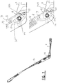
- said part of the mounting head 11 extends between the side walls 16,17 of the arm member 13 and beyond said pivot pin 14 is provided on its upper side with a blockage 25 acting as a stop surface to the base 18 of the U-shaped arm member 13 in a "rest position", that is in unmounted position.
- a hook-shaped bracket 26 connected to a spring 27 is hooked with its first end on a pin 28 on the mounting head 11 and with its second end onto a part 29 of the arm member 13 in order to ensure that the arm member 13 and thus the wiper blade 2 connected thereto is pressed onto a windscreen to be wiped.
- Both the pivot pin 14 and the pin 28 are located above said hook-shaped element 26, so that side walls 16,17 of the arm member 13 cover said grooves 22 from the outside in all positions of the arm member 13 relative to the mounting head 11. Consequently, the grooves 22 are not visible from the outside. Further, dust and/or ice is prevented to enter the grooves 22, so that an efficient and reliable articulation between said arm member 13 and said mounting head 11 is maintained at all times.
- said stop surfaces 23,24 are located at the other side of a central axis 30 of the spring 27 than the pivot pin or rivet 14.
Claims (12)
- Bras d'essuie-glace (8), en particulier pour automobiles, comprenant une tête de montage (11) pouvant être montée sur un arbre d'entraînement (12) et un élément de bras (13) raccordé, de manière pivotante, à la tête de montage (11) au moyen d'une broche de pivot (14), dans lequel l'élément de bras (13) a une section transversale sensiblement en forme de U à proximité de ladite broche de pivot (14) comprenant deux parois latérales (16, 17), dans lequel une partie de la tête de montage (11) s'étend entre les parois latérales (16, 17) et au-delà de ladite broche de pivot (14), dans lequel ladite partie est prévue avec des surfaces de butée (20, 21) opposées pour venir en butée contre les parois latérales (16, 17) de l'élément de bras (13), dans lequel on prévoit des moyens sur ladite tête de montage (11) et ledit élément de bras (13) pour limiter un angle de pivot de l'élément de bras (13), caractérisé en ce que lesdits moyens comprennent au moins une rainure de guidage (22) sur l'une desdites surfaces de butée (20, 21) de ladite partie de ladite tête de montage (11), ainsi qu'au moins un doigt s'étendant vers l'extérieur (19) sur ledit élément de bras (13), coopérant avec ladite rainure de guidage (22), dans lequel ledit doigt (19) est mobile dans ladite rainure de guidage (22) entre une première position correspondant à une position d'essuyage de l'élément de bras (13) et une seconde position correspondant à une position de montage de l'élément de bras (13), et dans lequel ledit doigt (19) s'étend vers l'extérieur à partir d'une base (18) de la section transversale en forme de U dudit élément de bras (13) dans une direction vers ledit arbre d'entraînement (12).
- Bras d'essuie-glace (8) selon la revendication 1, dans lequel, dans une position d'essuyage de l'élément de bras (13), l'une des parois latérales (16, 17) de l'élément de bras (13) recouvre ladite rainure de guidage (22) depuis l'extérieur.
- Bras d'essuie-glace (8) selon la revendication 1 ou 2, dans lequel ledit doigt (19) est incurvé.
- Bras d'essuie-glace (8) selon la revendication 1, 2 ou 3, dans lequel ladite rainure de guidage (22) est incurvée.
- Bras d'essuie-glace (8) selon la revendication 4, dans lequel ladite rainure de guidage (22) s'étend le long d'une partie d'un cercle.
- Bras d'essuie-glace (8) selon l'une quelconque des revendications 1 à 5, dans lequel lesdits moyens comprennent deux rainures de guidage (22) sur chaque surface de butée (20, 21) de ladite partie de ladite tête de montage (11), ainsi que deux doigts (19) s'étendant vers l'extérieur sur ledit élément de bras (13), chacun coopérant avec une rainure de guidage (22).
- Bras d'essuie-glace (8) selon l'une quelconque des revendications 1 à 6, dans lequel l'élément de bras (13) est réalisé à partir d'un métal, tel que l'acier.
- Dispositif d'essuie-glace (1) comprenant un bras d'essuie-glace (8) selon l'une quelconque des revendications 1 à 7.
- Dispositif d'essuie-glace (1) selon la revendication 8, dans lequel il comprend un élément de support élastique, allongé, ainsi qu'un balai d'essuie-glace allongé (2) en matériau flexible, qui peut être placé en butée contre un pare-brise à essuyer, lequel balai d'essuie-glace (2) comprend au moins une rainure longitudinale (3), dans laquelle rainure (3), est disposée une bande longitudinale (4) de l'élément de support, dans lequel les extrémités (5) de ladite bande longitudinale (4) sont raccordées avec une pièce de raccordement (6) respective, lequel dispositif d'essuie-glace (1) comprend un dispositif de raccordement (7) pour le bras d'essuie-glace (8) selon l'une quelconque des revendications 1 à 7.
- Procédé pour fabriquer un bras d'essuie-glace (8), en particulier pour automobiles, comprenant une tête de montage (11) pouvant être montée sur un arbre d'entraînement (12) et un élément de bras (13) raccordé de manière pivotante à la tête de montage (11) au moyen d'une broche de pivot (14), dans lequel l'élément de bras (13) a une section transversale sensiblement en forme de U à proximité de ladite broche de pivot (14) comprenant deux parois latérales (16, 17), dans lequel une partie de la tête de montage (11) s'étend entre les parois latérales (16, 17) et au-delà de ladite broche de pivot (14), dans lequel ladite partie est prévue avec des surfaces de butée (20, 21) opposées pour venir en butée contre les parois latérales (16, 17) de l'élément de bras (13), dans lequel on prévoit des moyens sur ladite tête de montage (11) et ledit élément de bras (13) pour limiter un angle de pivot de l'élément de bras (13), caractérisé en ce que lesdits moyens sont prévus avec au moins une rainure de guidage (22) sur l'une desdites surfaces de butée (20, 21) de ladite partie de ladite tête de montage (11), ainsi qu'avec au moins un doigt (19) s'étendant vers l'extérieur sur ledit élément de bras (13) coopérant avec ladite rainure de guidage (22), dans lequel ledit doigt (19) est mobile dans ladite rainure (22) entre une première position correspondant à une position d'essuyage de l'élément de bras (13) et une seconde position correspondant à une position de montage de l'élément de bras (13), et dans lequel ledit doigt (19) s'étend vers l'extérieur à partir d'une base (18) de la section transversale en forme de U dudit élément de bras (13) dans une direction allant vers ledit arbre d'entraînement (12).
- Bras d'essuie-glace (8), en particulier pour automobiles, comprenant un élément de bras (13) agencé pour être raccordé de manière pivotante à une tête de montage (18) au moyen d'une broche de pivot (14), dans lequel l'élément de bras (13) a une section transversale sensiblement en forme de U à proximité de ladite broche de pivot (14) comprenant deux parois latérales (16, 17) agencées pour loger une partie de la tête de montage (11) s'étendant entre les parois latérales (16, 17) et au-delà de ladite broche de pivot (14), dans lequel lesdites parois latérales (16,17) de l'élément de bras (13) sont agencées pour venir en butée contre des surfaces de butée (20, 21) opposées de ladite partie, dans lequel on prévoit des moyens sur ledit élément de bras (13) pour limiter un angle de pivot de l'élément de bras (13), caractérisé en ce que lesdits moyens comprennent deux doigts (19) s'étendant vers l'extérieur sur ledit élément de bras (13), chacun agencé pour coopérer avec une rainure de guidage (22) agencée sur chaque surface de butée (20, 21) de ladite partie de ladite tête de montage (11), dans lequel lesdits doigts (19) sont mobiles dans lesdites rainures de guidage (22) entre une première position correspondant à une position d'essuyage de l'élément de bras (13) et une seconde position correspondant à une position de montage de l'élément de bras (13) et dans lequel lesdits doigts (19) s'étendent vers l'extérieur à partir d'une base (18) de la section transversale en forme de U dudit élément de bras (13) dans une direction allant vers ledit arbre d'entraînement (12).
- Bras d'essuie-glace (8), en particulier pour automobiles, comprenant une tête de montage (11) pouvant être montée sur un arbre d'entraînement (12) et agencée pour être raccordée de manière pivotante à un élément de bras (13) au moyen d'une broche de pivot (14), dans lequel une partie de la tête de montage (11) est agencée pour s'étendre entre les parois latérales (16, 17) d'une section transversale sensiblement en forme de U de l'élément de bras (12) à proximité de ladite broche de pivot (14) et au-delà de ladite broche de pivot (14), dans lequel ladite partie est prévue avec des surfaces de butée (20, 21) opposées pour venir en butée entre les parois latérales (16, 17) de l'élément de bras (13), dans lequel on prévoit des moyens sur ladite tête de montage (11) pour limiter un angle de pivot de l'élément de bras (13), caractérisé en ce que lesdits moyens comprennent au moins une rainure de guidage (22) sur l'une desdites surface de butée (20, 21) de ladite partie de ladite tête de montage (11) agencée pour coopérer avec au moins un doigt (19) s'étendant vers l'extérieur sur ledit élément de bras (13) s'étendant vers l'extérieur à partir d'une base (18) de la section transversale en forme de U dudit élément de bras (13) dans une direction allant vers ledit arbre d'entraînement (12), dans lequel ladite rainure de guidage (22) est agencée pour permettre le mouvement dudit doigt (13) entre une première position correspondant à une position d'essuyage de l'élément de bras (13) et une seconde position correspondant à une position de montage de l'élément de bras (13).
Priority Applications (1)
| Application Number | Priority Date | Filing Date | Title |
|---|---|---|---|
| PL12714665T PL2834111T3 (pl) | 2012-04-05 | 2012-04-05 | Ramię wycieraczki szyby przedniej i sposób jego wytwarzania |
Applications Claiming Priority (1)
| Application Number | Priority Date | Filing Date | Title |
|---|---|---|---|
| PCT/EP2012/056356 WO2013149676A1 (fr) | 2012-04-05 | 2012-04-05 | Bras d'essuie-glace de pare-brise et procédé pour sa production |
Publications (2)
| Publication Number | Publication Date |
|---|---|
| EP2834111A1 EP2834111A1 (fr) | 2015-02-11 |
| EP2834111B1 true EP2834111B1 (fr) | 2020-02-26 |
Family
ID=45974318
Family Applications (1)
| Application Number | Title | Priority Date | Filing Date |
|---|---|---|---|
| EP12714665.2A Active EP2834111B1 (fr) | 2012-04-05 | 2012-04-05 | Bras d'essuie-glace de pare-brise et procédé pour sa production |
Country Status (11)
| Country | Link |
|---|---|
| US (1) | US9393934B2 (fr) |
| EP (1) | EP2834111B1 (fr) |
| JP (1) | JP6037359B2 (fr) |
| KR (1) | KR101933754B1 (fr) |
| CN (1) | CN104379415B (fr) |
| CA (1) | CA2869591A1 (fr) |
| IN (1) | IN2014DN09135A (fr) |
| MX (1) | MX349512B (fr) |
| PL (1) | PL2834111T3 (fr) |
| RU (1) | RU2586788C2 (fr) |
| WO (1) | WO2013149676A1 (fr) |
Families Citing this family (8)
| Publication number | Priority date | Publication date | Assignee | Title |
|---|---|---|---|---|
| FR3022514B1 (fr) * | 2014-06-20 | 2018-01-12 | Valeo Systemes D'essuyage | Ensemble d’essuyage d’une vitre de vehicule automobile comportant une tete de montage et un bras d’entrainement |
| WO2016167090A1 (fr) * | 2015-04-17 | 2016-10-20 | 株式会社ミツバ | Système d'essuie-glace |
| DE102017113632B4 (de) * | 2017-06-21 | 2021-06-24 | Dr. Ing. H.C. F. Porsche Aktiengesellschaft | Scheibenwischer |
| US20210155204A1 (en) * | 2017-07-03 | 2021-05-27 | Volvo Truck Corporation | Wiper arm assembly for a vehicle windscreen wiper system |
| CN108297833A (zh) * | 2017-08-18 | 2018-07-20 | 芜湖乐普汽车科技有限公司 | 一种雨刮器的雨刷传动机构的制造方法 |
| DE102017130945A1 (de) * | 2017-12-21 | 2019-06-27 | Valeo Wischersysteme Gmbh | Wischarmeinrichtung zum Reinigen einer Fahrzeugscheibe und Verwendung der Wischarmeinrichtung |
| EP3737592B1 (fr) * | 2018-01-08 | 2022-03-09 | Federal-Mogul S.A. | Bras d'essuie-glace, en particulier pour automobiles |
| CN108382359B (zh) * | 2018-04-16 | 2023-08-01 | 宁波市叶兴汽车零部件有限公司 | 一种雨刮板 |
Family Cites Families (10)
| Publication number | Priority date | Publication date | Assignee | Title |
|---|---|---|---|---|
| US2838782A (en) * | 1955-02-23 | 1958-06-17 | Gen Motors Corp | Windshield wiper arm |
| FR2518032A1 (fr) * | 1981-12-11 | 1983-06-17 | Marchal Equip Auto | Element d'essuie-glace comportant un bras d'essuie-glace soumis a l'action d'un ressort de compression par l'intermediaire d'une equerre de butee |
| JP2001010450A (ja) * | 1999-06-29 | 2001-01-16 | Asmo Co Ltd | 車両用ワイパ装置 |
| DE19951440B4 (de) * | 1999-10-25 | 2015-04-02 | Robert Bosch Gmbh | Wischarm für ein Fahrzeug |
| DE10008644A1 (de) | 2000-02-24 | 2001-09-13 | Bosch Gmbh Robert | Scheibenwischerarm |
| DE10120467A1 (de) * | 2001-04-26 | 2002-10-31 | Bosch Gmbh Robert | Wischblatt zum Reinigen von Scheiben, insbesondere von Kraftfahrzeugen |
| EP1359073B1 (fr) * | 2002-05-03 | 2006-07-12 | Federal-Mogul S.A. | Dispositif d'essuie-glace |
| DE10322058B4 (de) * | 2003-05-15 | 2017-03-23 | Robert Bosch Gmbh | Wischblatt |
| EP1514752B1 (fr) * | 2003-09-11 | 2007-06-20 | Federal-Mogul S.A. | Bras d'essuie-glace |
| JP4985538B2 (ja) * | 2008-05-07 | 2012-07-25 | 市光工業株式会社 | ワイパーアーム |
-
2012
- 2012-04-05 CN CN201280073656.5A patent/CN104379415B/zh not_active Expired - Fee Related
- 2012-04-05 RU RU2014144410/11A patent/RU2586788C2/ru not_active IP Right Cessation
- 2012-04-05 CA CA2869591A patent/CA2869591A1/fr not_active Abandoned
- 2012-04-05 JP JP2015503769A patent/JP6037359B2/ja not_active Expired - Fee Related
- 2012-04-05 KR KR1020147029282A patent/KR101933754B1/ko active IP Right Grant
- 2012-04-05 EP EP12714665.2A patent/EP2834111B1/fr active Active
- 2012-04-05 MX MX2014011984A patent/MX349512B/es active IP Right Grant
- 2012-04-05 PL PL12714665T patent/PL2834111T3/pl unknown
- 2012-04-05 US US14/390,840 patent/US9393934B2/en active Active
- 2012-04-05 WO PCT/EP2012/056356 patent/WO2013149676A1/fr active Application Filing
-
2014
- 2014-10-31 IN IN9135DEN2014 patent/IN2014DN09135A/en unknown
Non-Patent Citations (1)
| Title |
|---|
| None * |
Also Published As
| Publication number | Publication date |
|---|---|
| CN104379415A (zh) | 2015-02-25 |
| JP6037359B2 (ja) | 2016-12-07 |
| KR101933754B1 (ko) | 2018-12-28 |
| JP2015512350A (ja) | 2015-04-27 |
| PL2834111T3 (pl) | 2020-07-13 |
| US9393934B2 (en) | 2016-07-19 |
| MX349512B (es) | 2017-08-02 |
| RU2014144410A (ru) | 2016-05-27 |
| KR20150006834A (ko) | 2015-01-19 |
| EP2834111A1 (fr) | 2015-02-11 |
| MX2014011984A (es) | 2015-04-08 |
| US20150158462A1 (en) | 2015-06-11 |
| WO2013149676A1 (fr) | 2013-10-10 |
| CN104379415B (zh) | 2017-07-21 |
| CA2869591A1 (fr) | 2013-10-10 |
| IN2014DN09135A (fr) | 2015-05-22 |
| RU2586788C2 (ru) | 2016-06-10 |
Similar Documents
| Publication | Publication Date | Title |
|---|---|---|
| EP2834111B1 (fr) | Bras d'essuie-glace de pare-brise et procédé pour sa production | |
| EP1514752B1 (fr) | Bras d'essuie-glace | |
| EP2560847B1 (fr) | Dispositif d'essuie-glace | |
| EP2421729B1 (fr) | Dispositif d'essuie-glace | |
| EP2143602B2 (fr) | Dispositif d'essuie-glace | |
| EP2790969B1 (fr) | Bras d'essuie-glace | |
| EP2790970B1 (fr) | Balai d'essuie-glace | |
| EP2864161B1 (fr) | Bras d'essuie-glace | |
| EP1810898A1 (fr) | Bras d'essuie-glace | |
| EP2045153B1 (fr) | Dispositif d'essuie-glace | |
| US20080184516A1 (en) | Windscreen Wiper Arm | |
| WO2011026507A1 (fr) | Dispositif d'essuie-glace pour pare-brise |
Legal Events
| Date | Code | Title | Description |
|---|---|---|---|
| PUAI | Public reference made under article 153(3) epc to a published international application that has entered the european phase |
Free format text: ORIGINAL CODE: 0009012 |
|
| 17P | Request for examination filed |
Effective date: 20141008 |
|
| AK | Designated contracting states |
Kind code of ref document: A1 Designated state(s): AL AT BE BG CH CY CZ DE DK EE ES FI FR GB GR HR HU IE IS IT LI LT LU LV MC MK MT NL NO PL PT RO RS SE SI SK SM TR |
|
| AX | Request for extension of the european patent |
Extension state: BA ME |
|
| DAX | Request for extension of the european patent (deleted) | ||
| STAA | Information on the status of an ep patent application or granted ep patent |
Free format text: STATUS: EXAMINATION IS IN PROGRESS |
|
| 17Q | First examination report despatched |
Effective date: 20161223 |
|
| GRAP | Despatch of communication of intention to grant a patent |
Free format text: ORIGINAL CODE: EPIDOSNIGR1 |
|
| STAA | Information on the status of an ep patent application or granted ep patent |
Free format text: STATUS: GRANT OF PATENT IS INTENDED |
|
| INTG | Intention to grant announced |
Effective date: 20191009 |
|
| GRAS | Grant fee paid |
Free format text: ORIGINAL CODE: EPIDOSNIGR3 |
|
| GRAA | (expected) grant |
Free format text: ORIGINAL CODE: 0009210 |
|
| STAA | Information on the status of an ep patent application or granted ep patent |
Free format text: STATUS: THE PATENT HAS BEEN GRANTED |
|
| AK | Designated contracting states |
Kind code of ref document: B1 Designated state(s): AL AT BE BG CH CY CZ DE DK EE ES FI FR GB GR HR HU IE IS IT LI LT LU LV MC MK MT NL NO PL PT RO RS SE SI SK SM TR |
|
| REG | Reference to a national code |
Ref country code: GB Ref legal event code: FG4D |
|
| REG | Reference to a national code |
Ref country code: CH Ref legal event code: EP |
|
| REG | Reference to a national code |
Ref country code: DE Ref legal event code: R096 Ref document number: 602012068042 Country of ref document: DE |
|
| REG | Reference to a national code |
Ref country code: AT Ref legal event code: REF Ref document number: 1237242 Country of ref document: AT Kind code of ref document: T Effective date: 20200315 |
|
| REG | Reference to a national code |
Ref country code: IE Ref legal event code: FG4D |
|
| PG25 | Lapsed in a contracting state [announced via postgrant information from national office to epo] |
Ref country code: FI Free format text: LAPSE BECAUSE OF FAILURE TO SUBMIT A TRANSLATION OF THE DESCRIPTION OR TO PAY THE FEE WITHIN THE PRESCRIBED TIME-LIMIT Effective date: 20200226 Ref country code: NO Free format text: LAPSE BECAUSE OF FAILURE TO SUBMIT A TRANSLATION OF THE DESCRIPTION OR TO PAY THE FEE WITHIN THE PRESCRIBED TIME-LIMIT Effective date: 20200526 Ref country code: RS Free format text: LAPSE BECAUSE OF FAILURE TO SUBMIT A TRANSLATION OF THE DESCRIPTION OR TO PAY THE FEE WITHIN THE PRESCRIBED TIME-LIMIT Effective date: 20200226 |
|
| REG | Reference to a national code |
Ref country code: NL Ref legal event code: MP Effective date: 20200226 |
|
| REG | Reference to a national code |
Ref country code: LT Ref legal event code: MG4D |
|
| PG25 | Lapsed in a contracting state [announced via postgrant information from national office to epo] |
Ref country code: BG Free format text: LAPSE BECAUSE OF FAILURE TO SUBMIT A TRANSLATION OF THE DESCRIPTION OR TO PAY THE FEE WITHIN THE PRESCRIBED TIME-LIMIT Effective date: 20200526 Ref country code: LV Free format text: LAPSE BECAUSE OF FAILURE TO SUBMIT A TRANSLATION OF THE DESCRIPTION OR TO PAY THE FEE WITHIN THE PRESCRIBED TIME-LIMIT Effective date: 20200226 Ref country code: IS Free format text: LAPSE BECAUSE OF FAILURE TO SUBMIT A TRANSLATION OF THE DESCRIPTION OR TO PAY THE FEE WITHIN THE PRESCRIBED TIME-LIMIT Effective date: 20200626 Ref country code: SE Free format text: LAPSE BECAUSE OF FAILURE TO SUBMIT A TRANSLATION OF THE DESCRIPTION OR TO PAY THE FEE WITHIN THE PRESCRIBED TIME-LIMIT Effective date: 20200226 Ref country code: HR Free format text: LAPSE BECAUSE OF FAILURE TO SUBMIT A TRANSLATION OF THE DESCRIPTION OR TO PAY THE FEE WITHIN THE PRESCRIBED TIME-LIMIT Effective date: 20200226 Ref country code: GR Free format text: LAPSE BECAUSE OF FAILURE TO SUBMIT A TRANSLATION OF THE DESCRIPTION OR TO PAY THE FEE WITHIN THE PRESCRIBED TIME-LIMIT Effective date: 20200527 |
|
| PGFP | Annual fee paid to national office [announced via postgrant information from national office to epo] |
Ref country code: PL Payment date: 20200427 Year of fee payment: 9 Ref country code: BE Payment date: 20200423 Year of fee payment: 9 |
|
| PG25 | Lapsed in a contracting state [announced via postgrant information from national office to epo] |
Ref country code: NL Free format text: LAPSE BECAUSE OF FAILURE TO SUBMIT A TRANSLATION OF THE DESCRIPTION OR TO PAY THE FEE WITHIN THE PRESCRIBED TIME-LIMIT Effective date: 20200226 |
|
| PG25 | Lapsed in a contracting state [announced via postgrant information from national office to epo] |
Ref country code: SK Free format text: LAPSE BECAUSE OF FAILURE TO SUBMIT A TRANSLATION OF THE DESCRIPTION OR TO PAY THE FEE WITHIN THE PRESCRIBED TIME-LIMIT Effective date: 20200226 Ref country code: DK Free format text: LAPSE BECAUSE OF FAILURE TO SUBMIT A TRANSLATION OF THE DESCRIPTION OR TO PAY THE FEE WITHIN THE PRESCRIBED TIME-LIMIT Effective date: 20200226 Ref country code: EE Free format text: LAPSE BECAUSE OF FAILURE TO SUBMIT A TRANSLATION OF THE DESCRIPTION OR TO PAY THE FEE WITHIN THE PRESCRIBED TIME-LIMIT Effective date: 20200226 Ref country code: SM Free format text: LAPSE BECAUSE OF FAILURE TO SUBMIT A TRANSLATION OF THE DESCRIPTION OR TO PAY THE FEE WITHIN THE PRESCRIBED TIME-LIMIT Effective date: 20200226 Ref country code: PT Free format text: LAPSE BECAUSE OF FAILURE TO SUBMIT A TRANSLATION OF THE DESCRIPTION OR TO PAY THE FEE WITHIN THE PRESCRIBED TIME-LIMIT Effective date: 20200719 Ref country code: RO Free format text: LAPSE BECAUSE OF FAILURE TO SUBMIT A TRANSLATION OF THE DESCRIPTION OR TO PAY THE FEE WITHIN THE PRESCRIBED TIME-LIMIT Effective date: 20200226 Ref country code: CZ Free format text: LAPSE BECAUSE OF FAILURE TO SUBMIT A TRANSLATION OF THE DESCRIPTION OR TO PAY THE FEE WITHIN THE PRESCRIBED TIME-LIMIT Effective date: 20200226 Ref country code: LT Free format text: LAPSE BECAUSE OF FAILURE TO SUBMIT A TRANSLATION OF THE DESCRIPTION OR TO PAY THE FEE WITHIN THE PRESCRIBED TIME-LIMIT Effective date: 20200226 Ref country code: ES Free format text: LAPSE BECAUSE OF FAILURE TO SUBMIT A TRANSLATION OF THE DESCRIPTION OR TO PAY THE FEE WITHIN THE PRESCRIBED TIME-LIMIT Effective date: 20200226 |
|
| REG | Reference to a national code |
Ref country code: AT Ref legal event code: MK05 Ref document number: 1237242 Country of ref document: AT Kind code of ref document: T Effective date: 20200226 |
|
| REG | Reference to a national code |
Ref country code: DE Ref legal event code: R097 Ref document number: 602012068042 Country of ref document: DE |
|
| PG25 | Lapsed in a contracting state [announced via postgrant information from national office to epo] |
Ref country code: MC Free format text: LAPSE BECAUSE OF FAILURE TO SUBMIT A TRANSLATION OF THE DESCRIPTION OR TO PAY THE FEE WITHIN THE PRESCRIBED TIME-LIMIT Effective date: 20200226 |
|
| REG | Reference to a national code |
Ref country code: CH Ref legal event code: PL |
|
| PLBE | No opposition filed within time limit |
Free format text: ORIGINAL CODE: 0009261 |
|
| STAA | Information on the status of an ep patent application or granted ep patent |
Free format text: STATUS: NO OPPOSITION FILED WITHIN TIME LIMIT |
|
| PG25 | Lapsed in a contracting state [announced via postgrant information from national office to epo] |
Ref country code: IT Free format text: LAPSE BECAUSE OF FAILURE TO SUBMIT A TRANSLATION OF THE DESCRIPTION OR TO PAY THE FEE WITHIN THE PRESCRIBED TIME-LIMIT Effective date: 20200226 Ref country code: AT Free format text: LAPSE BECAUSE OF FAILURE TO SUBMIT A TRANSLATION OF THE DESCRIPTION OR TO PAY THE FEE WITHIN THE PRESCRIBED TIME-LIMIT Effective date: 20200226 Ref country code: CH Free format text: LAPSE BECAUSE OF NON-PAYMENT OF DUE FEES Effective date: 20200430 Ref country code: LI Free format text: LAPSE BECAUSE OF NON-PAYMENT OF DUE FEES Effective date: 20200430 Ref country code: LU Free format text: LAPSE BECAUSE OF NON-PAYMENT OF DUE FEES Effective date: 20200405 |
|
| 26N | No opposition filed |
Effective date: 20201127 |
|
| PG25 | Lapsed in a contracting state [announced via postgrant information from national office to epo] |
Ref country code: SI Free format text: LAPSE BECAUSE OF FAILURE TO SUBMIT A TRANSLATION OF THE DESCRIPTION OR TO PAY THE FEE WITHIN THE PRESCRIBED TIME-LIMIT Effective date: 20200226 |
|
| GBPC | Gb: european patent ceased through non-payment of renewal fee |
Effective date: 20200526 |
|
| PG25 | Lapsed in a contracting state [announced via postgrant information from national office to epo] |
Ref country code: IE Free format text: LAPSE BECAUSE OF NON-PAYMENT OF DUE FEES Effective date: 20200405 Ref country code: GB Free format text: LAPSE BECAUSE OF NON-PAYMENT OF DUE FEES Effective date: 20200526 |
|
| REG | Reference to a national code |
Ref country code: BE Ref legal event code: MM Effective date: 20210430 |
|
| PG25 | Lapsed in a contracting state [announced via postgrant information from national office to epo] |
Ref country code: TR Free format text: LAPSE BECAUSE OF FAILURE TO SUBMIT A TRANSLATION OF THE DESCRIPTION OR TO PAY THE FEE WITHIN THE PRESCRIBED TIME-LIMIT Effective date: 20200226 Ref country code: MT Free format text: LAPSE BECAUSE OF FAILURE TO SUBMIT A TRANSLATION OF THE DESCRIPTION OR TO PAY THE FEE WITHIN THE PRESCRIBED TIME-LIMIT Effective date: 20200226 Ref country code: CY Free format text: LAPSE BECAUSE OF FAILURE TO SUBMIT A TRANSLATION OF THE DESCRIPTION OR TO PAY THE FEE WITHIN THE PRESCRIBED TIME-LIMIT Effective date: 20200226 |
|
| PG25 | Lapsed in a contracting state [announced via postgrant information from national office to epo] |
Ref country code: MK Free format text: LAPSE BECAUSE OF FAILURE TO SUBMIT A TRANSLATION OF THE DESCRIPTION OR TO PAY THE FEE WITHIN THE PRESCRIBED TIME-LIMIT Effective date: 20200226 Ref country code: AL Free format text: LAPSE BECAUSE OF FAILURE TO SUBMIT A TRANSLATION OF THE DESCRIPTION OR TO PAY THE FEE WITHIN THE PRESCRIBED TIME-LIMIT Effective date: 20200226 |
|
| PG25 | Lapsed in a contracting state [announced via postgrant information from national office to epo] |
Ref country code: BE Free format text: LAPSE BECAUSE OF NON-PAYMENT OF DUE FEES Effective date: 20210430 |
|
| PG25 | Lapsed in a contracting state [announced via postgrant information from national office to epo] |
Ref country code: PL Free format text: LAPSE BECAUSE OF NON-PAYMENT OF DUE FEES Effective date: 20210405 |
|
| PGFP | Annual fee paid to national office [announced via postgrant information from national office to epo] |
Ref country code: FR Payment date: 20230425 Year of fee payment: 12 Ref country code: DE Payment date: 20230427 Year of fee payment: 12 |