EP1512920A1 - Luftbefeuchtungsvorrichtung - Google Patents
Luftbefeuchtungsvorrichtung Download PDFInfo
- Publication number
- EP1512920A1 EP1512920A1 EP03020139A EP03020139A EP1512920A1 EP 1512920 A1 EP1512920 A1 EP 1512920A1 EP 03020139 A EP03020139 A EP 03020139A EP 03020139 A EP03020139 A EP 03020139A EP 1512920 A1 EP1512920 A1 EP 1512920A1
- Authority
- EP
- European Patent Office
- Prior art keywords
- injection means
- pressure
- fluid
- groups
- bar
- Prior art date
- Legal status (The legal status is an assumption and is not a legal conclusion. Google has not performed a legal analysis and makes no representation as to the accuracy of the status listed.)
- Granted
Links
- 238000002347 injection Methods 0.000 claims abstract description 96
- 239000007924 injection Substances 0.000 claims abstract description 96
- XLYOFNOQVPJJNP-UHFFFAOYSA-N water Substances O XLYOFNOQVPJJNP-UHFFFAOYSA-N 0.000 claims abstract description 33
- 238000001816 cooling Methods 0.000 claims abstract description 10
- 239000012530 fluid Substances 0.000 claims description 47
- 239000007921 spray Substances 0.000 claims description 6
- 230000003247 decreasing effect Effects 0.000 claims description 2
- 230000003020 moisturizing effect Effects 0.000 abstract 2
- 239000013505 freshwater Substances 0.000 description 4
- 238000004140 cleaning Methods 0.000 description 3
- 238000001514 detection method Methods 0.000 description 2
- 230000001105 regulatory effect Effects 0.000 description 2
- 239000000243 solution Substances 0.000 description 2
- 238000004891 communication Methods 0.000 description 1
- 239000002826 coolant Substances 0.000 description 1
- 238000011161 development Methods 0.000 description 1
- 230000018109 developmental process Effects 0.000 description 1
- 238000000034 method Methods 0.000 description 1
- 238000012544 monitoring process Methods 0.000 description 1
- 238000003825 pressing Methods 0.000 description 1
- 238000001223 reverse osmosis Methods 0.000 description 1
Images
Classifications
-
- F—MECHANICAL ENGINEERING; LIGHTING; HEATING; WEAPONS; BLASTING
- F24—HEATING; RANGES; VENTILATING
- F24F—AIR-CONDITIONING; AIR-HUMIDIFICATION; VENTILATION; USE OF AIR CURRENTS FOR SCREENING
- F24F6/00—Air-humidification, e.g. cooling by humidification
- F24F6/12—Air-humidification, e.g. cooling by humidification by forming water dispersions in the air
- F24F6/14—Air-humidification, e.g. cooling by humidification by forming water dispersions in the air using nozzles
-
- F—MECHANICAL ENGINEERING; LIGHTING; HEATING; WEAPONS; BLASTING
- F24—HEATING; RANGES; VENTILATING
- F24F—AIR-CONDITIONING; AIR-HUMIDIFICATION; VENTILATION; USE OF AIR CURRENTS FOR SCREENING
- F24F6/00—Air-humidification, e.g. cooling by humidification
- F24F6/12—Air-humidification, e.g. cooling by humidification by forming water dispersions in the air
- F24F6/14—Air-humidification, e.g. cooling by humidification by forming water dispersions in the air using nozzles
- F24F2006/146—Air-humidification, e.g. cooling by humidification by forming water dispersions in the air using nozzles using pressurised water for spraying
-
- Y—GENERAL TAGGING OF NEW TECHNOLOGICAL DEVELOPMENTS; GENERAL TAGGING OF CROSS-SECTIONAL TECHNOLOGIES SPANNING OVER SEVERAL SECTIONS OF THE IPC; TECHNICAL SUBJECTS COVERED BY FORMER USPC CROSS-REFERENCE ART COLLECTIONS [XRACs] AND DIGESTS
- Y02—TECHNOLOGIES OR APPLICATIONS FOR MITIGATION OR ADAPTATION AGAINST CLIMATE CHANGE
- Y02B—CLIMATE CHANGE MITIGATION TECHNOLOGIES RELATED TO BUILDINGS, e.g. HOUSING, HOUSE APPLIANCES OR RELATED END-USER APPLICATIONS
- Y02B30/00—Energy efficient heating, ventilation or air conditioning [HVAC]
- Y02B30/54—Free-cooling systems
Definitions
- the invention relates to an air humidification device comprising at least a high pressure pump with a pump inlet and a pump outlet and at least two groups of injection means, wherein the High pressure pump to the injection means, if necessary, water supplies, in particular for direct or indirect humidification of a room or Cooling purposes, according to the preamble of claim 1.
- the invention also an injection means for injecting moistening fluid in air, preferably in an air stream, in particular for direct or indirect humidification of a room or for cooling purposes, in particular for use in an air humidification device according to claim 1.
- the object of the present invention is an air humidification device in which the injection means both at a work well both low and at a high rate of introduction. Furthermore, injection means are to be specified in which a trickling is avoided at low pressures.
- a core idea of the present invention is that injection means of different groups are designed and connected in such a way that they automatically open at different threshold pressures P A1 , P B1 ,... P G1 or that the injection means has a valve device which is acted upon by a defined bias voltage and comprises a valve piston and a valve seat, wherein the valve means opens only at a predetermined threshold pressure, thereby causing a fluid connection between the fluid inlet and the fluid outlet.
- the air humidification device is designed such that the injection means of a first group at a threshold pressure P A1 ⁇ 10 bar, in particular ⁇ 1 bar, in particular open immediately when water is supplied by the high-pressure pump, wherein the injection means of a second and possibly further groups at P A1 initially remain closed.
- P A1 ⁇ 10 bar in particular ⁇ 1 bar
- P A1 initially remain closed.
- the humidifying fluid if there is only a small amount of humidifying fluid to be introduced, can be introduced by the limited number of injection means of the first group with a correspondingly higher pressure than if all the injection means of the entire humidifying device were active immediately.
- the injection means are designed such that they close in the open state at decreasing pressure at a closing pressure P A2 , P B2 , ..., P G2 , wherein the respective closing pressure the respective threshold pressure P A1 , P B1 , .. P G1 , not less than 10 bar, preferably not more than 3 bar below.
- the injection means are preferably designed essentially in such a way that the closing pressure P A2 , P B2 ,..., P G2 corresponds to the respective threshold pressure P A1 , P B1 ,... P G1 .
- At least three to seven Groups of injectors with different threshold pressures be provided, wherein the injection means of the various groups such can be trained and connected, that the threshold pressures of the different groups by at least 10 bar, preferably around differ by at least 15 bar.
- threshold pressures of the individual injection means increase substantially in equal steps or if the Closing pressures also corresponding thereto substantially in the same Fall off steps.
- the according to an independent aspect of the present invention with a Valve device equipped injection means are characterized by that they open automatically at a predetermined threshold pressure or close automatically at a predetermined closing pressure.
- the independent one Opening or closing of the injection means takes place without external, in particular electronic control devices, but according to a preferred Aspect of the present invention purely mechanically.
- a biased biased Valve means comprise a spring, in particular a spiral spring, which provides the defined bias voltage.
- the spring, in particular the spiral spring is pre-set to provide an opening of the valve device a desired threshold pressure or closing at a desired Closing pressure guaranteed.
- valve piston against the flow direction of the dampening fluid through the bias, in particular the spring or spiral spring in the direction of the valve seat applied.
- the Befeuchtungsfluid thus flows against a valve seat associated end of the valve piston or the valve piston is in Open position arranged downstream of the valve seat.
- the injection means between fluid outlet and valve means still include a swirl generating device to a generated Spray jet of moistening fluid to impart a desired twist.
- each fluid outlet with a nozzle-like constriction and the valve device in a common unit in particular in a common unit Housing housed.
- each fluid outlet with a nozzle-like narrowing to connect a valve device according to the invention, which is not in a common housing is housed with the fluid outlet.
- a connecting piece may be provided which defines the fluid inlet, over which the assembly or the nozzle housing on a nozzle connect, in particular screws.
- a connecting piece may be provided which defines the fluid inlet, over which the assembly or the nozzle housing on a nozzle connect, in particular screws.
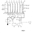
- a high pressure pump 11 has a pump inlet 12 and a pump outlet 13.
- the pump input is via a cleaning device 33 directly to a Fresh water inlet 34 connected without the interposition of a reservoir.
- the supplied from the fresh water network via the fresh water inlet 34 Water is descaled in the cleaning device 33, by reverse Osmosis purified and passes from there as fully demineralized water directly to the high-pressure pump 11. From the high-pressure pump 11 performs a common supply line 35 into a humidification chamber 32nd
- the nozzle block 26 for attachment of injection means 14, 15, 27, 28, 29, 30, 31 are formed (see FIG 2).
- one group of injectors is connected to a power train 36 A, B, C, D, E, F, G arranged.
- Each group A, ..., G comprises identical Injection means, group A the injection means 14, group B the injection means 15, group C, the injection means 27, group D, the injection means 28, group E, the injection means 29, group F, the injection means 30th and group G the injection means 31.
- the basic structure of the injection means 14, 15, 27, ..., 31 corresponds to FIG 2.
- Each injection means 14, 15, 27, 28, 29, 30, 31 is designed such that it from a threshold pressure P A1 , P B1 , P C1 , P D1 , P E1 , P F1 , P G1 opens independently in the lines 35, 36, that is, from a closed state to an open state, and from a closing pressure P A2 , P B2 , P C2 , P D2 , P E2 , P F2 , P G2 in the lines 35, 36 independently again from the open to the closed state pass.
- the threshold pressure P A1 , ..., P G1 and the closing pressure P A2 , ..., P G2 substantially are the same size.
- the identical injection means 14, 15, 27,..., 31 of a group A,..., G have a substantially identical threshold pressure P A1 ,..., P G1 , and a substantially identical closing pressure P A2 , ..., P G2 .
- the injection means 14, 15, 27, ..., 31 different group A, ..., G differ in terms of their threshold pressure P A1 , ..., P G1 and its closing pressure P A2 , ..., P G2 .
- the pressures in the illustrated embodiment are selected such that both the threshold pressures P A1 ,..., P G1 and the closing pressures P A2 ,..., P G2 of the injection means 14, 15, 27,. 31 differ between the individual groups A, ..., G by about 15 bar.
- the injection means 14 of group A have the smallest threshold pressure, about 0.5 bar.
- the threshold pressure of the injection means 15 of group B is about 15 bar larger and is about 15.5 bar
- the threshold pressure of the injection means 27 of group C is again about 15 bar larger and is at about 30.5 bar, etc. (analogous to group D, E, F and finally G).
- each of the line strands is connected 36 each have five identical injection means 14, 15, 27, ..., 31 arranged.
- each of the groups A, ..., G each includes five injection means 14, 15, 27, ..., 31.
- the groups A, ..., G each includes five injection means 14, 15, 27, ..., 31.
- a different number to injection elements in the respective groups possible and in many Use cases also useful.
- the embodiment described here is for operation in a humidification chamber 32 designed. In principle, however, the arrangement can also be included apply direct humidification. Uses are in addition to humidification a room to be humidified, alternatively and / or additionally the Cooling of an air or gas stream or of coolants or recooling media.
- the latter applications include adiabatic cooling and free cooling, as is traditional with cooling towers be achieved. For such cooling methods is on the disclosure content PCT / EP 02/08760.
- a room humidity sensor 37 the optional can be arranged in the room to be humidified or in the exhaust duct, and a Zuluftfeuchtetler 38 are provided, wherein the Zu povertyfeuchtereler 38 is disposed immediately after the humidification chamber 32.
- the humidity control 39 is in communication with a pump controller 40.
- the pump control 40 controls the high-pressure pump 11 via a frequency converter 41 based on the signal of the already mentioned humidity control 39.
- a pressure sensor 42 the pressure in the supply line 35 capture and possibly in the pump control 40 supplementary be taken into account. But according to the invention is a pressure detection in the Supply line 35 is not necessary, since the injection means 27 to 31 the each required amount of water through the specified pump pressure set yourself.
- the humidification takes place in the humidification device, by entering the air or air flow in the humidification chamber 32 a certain total amount of water is sprayed.
- the total amount of water is adjustable over the water pressure, the High pressure pump 11 is generated in the lines 35, 36.
- the individual groups are switched off by lowering the water pressure generated by the high-pressure pump 11 below the respective closing pressure P A2 ,..., P G2 of the injection means in the reverse order.
- the control of the high-pressure pump and thus of the generated by this Water pressure in the lines takes place in the described processes via the pump control 40, the signals of the humidity control 39th and optionally in addition, but not necessarily the pressure sensor 42 processed.
- the humidification device 1 shows that a small total amount of water only by a small number of injection means, for example only by the injection means 14 of the group A, is generated.
- the other injection means stay closed in this case.
- the one with one low water pressure associated risk of trickling of injectors is therefore significantly reduced by the described arrangement.
- the for the Generation of large quantities of water required number of injectors is achieved step by step by connecting the other groups B, ..., G.
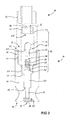
- FIG. 2 shows an exploded view of an embodiment of an inventive Injection means 14.
- the illustrated individual components are merged in a vertical direction. One can be seen each vertical section of the components.
- the injection means 14 comprises a nozzle housing 24 with a fluid inlet 16 at a first side 46 and a fluid outlet 17 at one of the first 46 opposite second side 49.
- the nozzle housing 24 has on the first side 46, a first internal thread 44.
- the first internal thread 44 defines a connecting piece 25, with which the injection means 14 can be screwed to a nozzle 26.
- the nozzle 26, a first external thread 45 which is connected to the first internal thread 44 of the Nozzle housing 24 corresponds.
- the injection means 14 supplied a pressurized fluid.
- a second internal thread 50 with a smaller compared to the first internal thread 44 thread diameter educated.
- the second internal thread 50 is a body 43 with a second, the second internal thread 44 corresponding external thread 51 attachable by screwing.
- the body 43 has in his Center on a through hole 48. Is the body 43 in the nozzle housing 24th attached, the through hole 48 forms the fluid inlet at its outer end 16 of the injection means 14 and at its inner end a valve seat 21 as part of a valve device 19th
- valve device 19 With the attachment of the body 43 in the nozzle housing 24 is simultaneously the valve device 19 in a first recess 47 of the nozzle housing 24, between a bottom 54 of the first recess 47 and the body 43, trained.
- the valve device 19 comprises a perforated disc 52, a Spiral spring 22, a valve piston 20, a shaft 55 and a front End 56 has, as well as the already mentioned valve seat 21st
- the coil spring 22 has a first side 57, one of the first side 57 opposite lying second side 58 and an interior 59.
- the shaft 55 of the valve piston 22 is located completely in the interior 59 of the coil spring, so that the coil spring with its second side 58 against a back 63 of the front end 56 of the valve piston 20 presses and the front end 56 of the valve piston thus pressed against the valve seat 21.
- valve seat 21 thus becomes closed fluid-tight by the front end 56 of the valve piston 20.
- the body 43 is screwed sealingly into the second internal thread 50.
- a second Recess 62 of the nozzle housing 24 At the bottom 54 of the first recess 47 is a second Recess 62 of the nozzle housing 24, whose diameter is smaller than the diameter of the first recess 47.
- This second recess 62nd connects the first recess 47 with the fluid outlet 17, which from a nozzle-like constriction 18 is formed.
- the fluid outlet 17 is embedded in a swirl generating device 23.
- the fluid passes after it has penetrated into the first recess 47 of the nozzle housing 24 via the second recess 62 of the nozzle housing 24 and the swirl generating device 23 to the fluid outlet 17. There, the fluid enters as a spray imprinted swirl from the nozzle housing 24 and thus from the injection means 14 off.
- an injection means 14 is provided that up to a threshold pressure P A1 closes and opens on reaching or exceeding the threshold pressure P A1, thereby generating a spray.
- the threshold pressure required for opening the injection means can be varied. In this way, for example, the injection means 14, 15, 27,..., 31 of the various groups A,..., G used in the air humidification device according to FIG. 1 and differing in their threshold pressure P A1, produce.
Landscapes
- Chemical & Material Sciences (AREA)
- Engineering & Computer Science (AREA)
- Dispersion Chemistry (AREA)
- Combustion & Propulsion (AREA)
- Mechanical Engineering (AREA)
- General Engineering & Computer Science (AREA)
- Air Humidification (AREA)
- Devices For Blowing Cold Air, Devices For Blowing Warm Air, And Means For Preventing Water Condensation In Air Conditioning Units (AREA)
- Air Conditioning Control Device (AREA)
- Thermotherapy And Cooling Therapy Devices (AREA)
Abstract
Description
- FIG 1
- eine Ausführungsform der erfindungsgemäßen Luftbefeuchtungseinrichtung in schematischer Darstellung und
- FIG 2
- eine Explosionsdarstellung einer Ausführungsform eines erfindungsgemäßen Einspritzmittels im Längsschnitt.
- 11
- Hochdruckpumpe
- 12
- Pumpeneingang
- 13
- Pumpenausgang
- 14, 15
- Einspritzmittel
- 16
- Fluideinlass
- 17
- Fluidauslass
- 18
- düsenartige Verengung
- 19
- Ventileinrichtung
- 20
- Ventilkolben
- 21
- Ventilsitz
- 22
- Spiralfeder
- 23
- Drallerzeugungseinrichtung
- 24
- Düsengehäuse
- 25
- Anschlussstutzen
- 26
- Düsenstock
- 27, 28, 29
- Einspritzmittel
- 30, 31
- Einspritzmittel
- 32
- Befeuchtungskammer
- 33
- Reinigungseinrichtung
- 34
- Frischwasserzulauf
- 35
- Versorgungsleitung
- 36
- Leitungsstränge
- 37
- Raumfeuchtefühler
- 38
- Zuluftfeuchtefühler
- 39
- Feuchtesteuerung
- 40
- Pumpensteuerung
- 41
- Frequenzumrichter
- 42
- Drucksensor
- 43
- Körper
- 44
- erstes Innengewinde
- 45
- erstes Außengewinde
- 46
- erste Seite
- 47
- erste Ausnehmung
- 48
- Durchgangsloch
- 49
- zweite Seite
- 50
- zweites Innengewinde
- 51
- zweits Außengewinde
- 52
- Lochscheibe
- 54
- Unterseite der Ausnehmung 47
- 55
- Schaft des Ventilkolbens 20
- 56
- vorderes Ende des Ventilkolbens 20
- 57
- erste Seite der Spiralfeder 22
- 58
- zweite Seite der Spiralfeder 22
- 59
- Innenraum der Spiralfeder 22
- 61
- Innenfläche
- 62
- zweite Ausnehmung
- 63
- Rückseite des vorderen Endes 56 des Ventilkolbens 20
- A, B, C, D, E, F, G
- Gruppen von Einspritzmitteln
- PA1, PB1, ..., PG1
- Schwellendrücke
- PA2, PB2, ..., PG2
- Schließdrücke
Claims (11)
- Luftbefeuchtungsvorrichtung, umfassend wenigstens eine Hochdruckpumpe mit einem Pumpeneingang (12) und einem Pumpenausgang (13) und mindestens zwei Gruppen (A, B, ...., G) von Einspritzmitteln (14, 15), wobei die Hochdruckpumpe (11) den Einspritzmitteln (14, 15, 27, ..., 31) bedarfsweise Wasser zuführt, insbesondere zur direkten oder indirekten Befeuchtung eines Raumes oder zu Kühlzwecken,
dadurch gekennzeichnet, dass die Einspritzmittel (14, 15, 27, ..., 31) der verschiedenen Gruppen (A, B, ...., G) derart ausgebildet und angeschlossen sind, dass sie bei unterschiedlichen Schwellendrücken PA1, PB1, ... PG1 selbständig öffnen. - Luftbefeuchtungsvorrichtung nach Anspruch 1,
dadurch gekennzeichnet, dass die Einspritzmittel (14) einer ersten Gruppe (A) bei einem Schwellendruck PA1 < 10 bar, insbesondere < 1 bar, insbesondere sofort bei Wasserzufuhr durch die Hochdruckpumpe öffnen, wobei die Einspritzmittel (15, 27, ..., 31) einer zweiten und ggf. weiterer Gruppen (B, ..., G) bei PA1 zunächst geschlossen bleiben. - Luftbefeuchtungsvorrichtung nach Anspruch 1 oder 2,
dadurch gekennzeichnet, dass die Einspritzmittel (14, 15, 27, ..., 31) in geöffnetem Zustand bei abfallendem Druck bei einem Schließdruck PA2, PB2, ... PG2 schließen, wobei die Einspritzmittel der verschiedenen Gruppen (A, B, ... G) derart ausgebildet und angeschlossen sind, dass der jeweilige Schließdruck PA2, PB2, ... PG2 den jeweiligen Schwellendruck PA1, PB1, ... PG1 um nicht mehr als 10 bar, vorzugsweise um nicht mehr als 3 bar unterschreitet. - Luftbefeuchtungsvorrichtung nach einem der Ansprüche 1 bis 3,
dadurch gekennzeichnet, dass drei bis sieben Gruppen (A, B, C, D, E, F, G) von Einspritzmitteln (14, 15, 27, ..., 31) mit unterschiedlichen Schwellendrücken (PA1, PB1, ... PG1) vorgesehen sind und dass die Einspritzmittel (14, 15, 27, ..., 31) der verschiedenen Gruppen (A, B, ... G) derart ausgebildet und angeschlossen sind, dass sich die Schwellendrücke (PA1, PB1, ... PG1) der verschiedenen Gruppen sich um mindestens 10 bar, vorzugsweise um mindestens 15 bar unterscheiden. - Luftbefeuchtungsvorrichtung nach einem der Ansprüche 1 bis 4,
dadurch gekennzeichnet, dass drei bis sieben Gruppen (A, B, C, D, E, F, G) von Einspritzmitteln (14, 15, 27, ..., 31) mit unterschiedlichen Schwellendrücken (PA1, PB1, ... PG1) vorgesehen sind und dass die Einspritzmittel (14, 15, 27, ..., 31) der verschiedenen Gruppen (A, B, ... G) derart ausgebildet und angeschlossen sind, dass die Schwellendrücke (PA1, PB1, ... PG1) im Wesentlichen in gleichen Schritten ansteigen. - Einspritzmittel zum Einspritzen von Befeuchtungsfluid in Luft, vorzugsweise in einen Luftstrom, insbesondere zur direkten oder indirekten Befeuchtung eines Raumes oder zu Kühlzwecken, insbesondere zur Verwendung in einer Luftbefeuchtungsvorrichtung nach Patentanspruch 1, umfassend einen Fluideinlass (16) und einen Fluidauslass (17) mit einer düsenartigen Verengung (18),
dadurch gekennzeichnet, dass eine mit einer definierten Vorspannung beaufschlagte Ventileinrichtung (19) umfassend einen Ventilkolben (20) und einen Ventilsitz (21) vorgesehen ist, die erst bei einem vorbestimmten Schwellendruck (PA1, PB1, ... PG1) öffnet und dabei eine Fluidverbindung zwischen Fluideinlass (16) und Fluidauslass (17) bewirkt. - Einspritzmittel nach Anspruch 6,
dadurch gekennzeichnet, dass die mit Vorspannung beaufschlagte Ventileinrichtung (19) eine Feder, insbesondere eine Spiralfeder (22) umfasst, welche die definierte Vorspannung bewirkt. - Einspritzmittel nach einem der Ansprüche 6 oder 7,
dadurch gekennzeichnet, dass der Ventilkolben (20) gegen die Strömungsrichtung des Befeuchtungsfluids durch die Vorspannung, insbesondere die Feder bzw. Spiralfeder (22) in Richtung auf den Ventilsitz (21) beaufschlagt wird. - Einspritzmittel nach einem der Ansprüche 6 bis 8,
dadurch gekennzeichnet, dass zwischen Fluidauslass (17) und Ventileinrichtung (19) eine Drallerzeugungseinrichtung (23) angeordnet ist, um einem erzeugten Sprühstrahl von Befeuchtungsfluid einen gewünschten Drall aufzuprägen. - Einspritzmittel nach einem der Ansprüche 6 bis 9,
dadurch gekennzeichnet, dass der Fluidauslass (17) mit der düsenartigen Verengung (18) und die Ventileinrichtung (19) in einer gemeinsamen Baueinheit, insbesondere in einem gemeinsamen Düsengehäuse (24) angeordnet sind. - Einspritzmittel nach einem der Ansprüche 6 bis 10,
dadurch gekennzeichnet, dass die Baueinheit bzw. das Düsengehäuse (24) über einen Anschlussstutzen (25), der den Fluideinlasss (16) definiert, an einem Düsenstock (26) anschließbar, insbesondere anschraubbar ist.
Priority Applications (4)
| Application Number | Priority Date | Filing Date | Title |
|---|---|---|---|
| DE20321005U DE20321005U1 (de) | 2003-09-05 | 2003-09-05 | Luftbefeuchtungsvorrichtung |
| EP03020139A EP1512920B1 (de) | 2003-09-05 | 2003-09-05 | Luftbefeuchtungsvorrichtung |
| AT03020139T ATE353131T1 (de) | 2003-09-05 | 2003-09-05 | Luftbefeuchtungsvorrichtung |
| DE50306435T DE50306435D1 (de) | 2003-09-05 | 2003-09-05 | Luftbefeuchtungsvorrichtung |
Applications Claiming Priority (1)
| Application Number | Priority Date | Filing Date | Title |
|---|---|---|---|
| EP03020139A EP1512920B1 (de) | 2003-09-05 | 2003-09-05 | Luftbefeuchtungsvorrichtung |
Publications (2)
| Publication Number | Publication Date |
|---|---|
| EP1512920A1 true EP1512920A1 (de) | 2005-03-09 |
| EP1512920B1 EP1512920B1 (de) | 2007-01-31 |
Family
ID=34130146
Family Applications (1)
| Application Number | Title | Priority Date | Filing Date |
|---|---|---|---|
| EP03020139A Expired - Lifetime EP1512920B1 (de) | 2003-09-05 | 2003-09-05 | Luftbefeuchtungsvorrichtung |
Country Status (3)
| Country | Link |
|---|---|
| EP (1) | EP1512920B1 (de) |
| AT (1) | ATE353131T1 (de) |
| DE (2) | DE50306435D1 (de) |
Cited By (3)
| Publication number | Priority date | Publication date | Assignee | Title |
|---|---|---|---|---|
| EP1830137A3 (de) * | 2006-02-21 | 2008-10-22 | Carel S.p.A. | Luftbefeuchtungssystem für große geschlossene Räume sowie Befeuchtungsmodul zur Verwendung in einem solchen System |
| DE202008013622U1 (de) | 2008-10-14 | 2008-12-18 | Michelbach, Ludwig | Druckgesteuerte Ventildüse |
| WO2018108746A1 (de) * | 2016-12-15 | 2018-06-21 | Eisenmann Se | Vorrichtung zum befeuchten eines luftstroms |
Citations (9)
| Publication number | Priority date | Publication date | Assignee | Title |
|---|---|---|---|---|
| GB774604A (en) * | 1954-11-29 | 1957-05-15 | William Murray | Improvements in and relating to self-actuating valves |
| US2921747A (en) * | 1958-08-14 | 1960-01-19 | Bosch Arma Corp | Nozzle |
| US4830046A (en) * | 1988-04-22 | 1989-05-16 | Hose Specialties/Capri, Inc. | Excess flow control valve |
| US5441202A (en) * | 1994-04-20 | 1995-08-15 | Wintering; Gary F. | Misting system with improved couplers |
| DE19614446C1 (de) * | 1996-04-12 | 1998-01-29 | Umeta Hermann Ulrichskoetter M | Fettpresse |
| US5765752A (en) * | 1996-01-26 | 1998-06-16 | Dgh Systems, L.L.C. | Airless atomizing nozzle and system for humidity control |
| DE19807683C1 (de) * | 1998-02-25 | 1999-09-30 | Ludwig Michelbach | Luftbefeuchtungsvorrichtung |
| DE10105397A1 (de) * | 2001-02-07 | 2002-08-08 | Draabe Industrietechnik Gmbh | Ansteuerung bei Luftbefeuchtern mit Nachverdunster |
| US20030034072A1 (en) * | 2001-08-20 | 2003-02-20 | Bui Quy B. | Valve assembly design |
-
2003
- 2003-09-05 DE DE50306435T patent/DE50306435D1/de not_active Expired - Lifetime
- 2003-09-05 DE DE20321005U patent/DE20321005U1/de not_active Expired - Lifetime
- 2003-09-05 AT AT03020139T patent/ATE353131T1/de active
- 2003-09-05 EP EP03020139A patent/EP1512920B1/de not_active Expired - Lifetime
Patent Citations (9)
| Publication number | Priority date | Publication date | Assignee | Title |
|---|---|---|---|---|
| GB774604A (en) * | 1954-11-29 | 1957-05-15 | William Murray | Improvements in and relating to self-actuating valves |
| US2921747A (en) * | 1958-08-14 | 1960-01-19 | Bosch Arma Corp | Nozzle |
| US4830046A (en) * | 1988-04-22 | 1989-05-16 | Hose Specialties/Capri, Inc. | Excess flow control valve |
| US5441202A (en) * | 1994-04-20 | 1995-08-15 | Wintering; Gary F. | Misting system with improved couplers |
| US5765752A (en) * | 1996-01-26 | 1998-06-16 | Dgh Systems, L.L.C. | Airless atomizing nozzle and system for humidity control |
| DE19614446C1 (de) * | 1996-04-12 | 1998-01-29 | Umeta Hermann Ulrichskoetter M | Fettpresse |
| DE19807683C1 (de) * | 1998-02-25 | 1999-09-30 | Ludwig Michelbach | Luftbefeuchtungsvorrichtung |
| DE10105397A1 (de) * | 2001-02-07 | 2002-08-08 | Draabe Industrietechnik Gmbh | Ansteuerung bei Luftbefeuchtern mit Nachverdunster |
| US20030034072A1 (en) * | 2001-08-20 | 2003-02-20 | Bui Quy B. | Valve assembly design |
Cited By (5)
| Publication number | Priority date | Publication date | Assignee | Title |
|---|---|---|---|---|
| EP1830137A3 (de) * | 2006-02-21 | 2008-10-22 | Carel S.p.A. | Luftbefeuchtungssystem für große geschlossene Räume sowie Befeuchtungsmodul zur Verwendung in einem solchen System |
| US7823865B2 (en) | 2006-02-21 | 2010-11-02 | Carel S.P.A. | Air humidification system for large enclosed spaces and humidification module usable in such system |
| DE202008013622U1 (de) | 2008-10-14 | 2008-12-18 | Michelbach, Ludwig | Druckgesteuerte Ventildüse |
| WO2018108746A1 (de) * | 2016-12-15 | 2018-06-21 | Eisenmann Se | Vorrichtung zum befeuchten eines luftstroms |
| CN110073150A (zh) * | 2016-12-15 | 2019-07-30 | 艾森曼欧洲公司 | 用于加湿气体流的设备 |
Also Published As
| Publication number | Publication date |
|---|---|
| ATE353131T1 (de) | 2007-02-15 |
| EP1512920B1 (de) | 2007-01-31 |
| DE20321005U1 (de) | 2005-09-15 |
| DE50306435D1 (de) | 2007-03-22 |
Similar Documents
| Publication | Publication Date | Title |
|---|---|---|
| CH699322A1 (de) | Verfahren zum einstellen eines helmholtz-resonators sowie helmholtz-resonator zur durchführung des verfahrens. | |
| DE10123775A1 (de) | Kraftstoff-Einspritzvorrichtung für Brennkraftmaschinen, insbesondere Common-Rail-Injektor, sowie Kraftstoffsystem und Brennkraftmaschine | |
| AT503660B1 (de) | Vorrichtung zum einspritzen von kraftstoff in den brennraum einer brennkraftmaschine | |
| EP3180104B1 (de) | Vorrichtung und verfahren zur auftrennung eines gasgemisches in einer membraneinheit | |
| DE2504892A1 (de) | Integrierte kraftlenkvorrichtung | |
| EP1213485B1 (de) | Vakuumerzeugervorrichtung sowie Verfahren zum Betreiben einer Vakuumerzeugervorrichtung | |
| DE2453734B2 (de) | ||
| DE10250532B3 (de) | Treibgas betriebene Ejektoranordnung | |
| DE112020001063T5 (de) | Hochdruck- SCR- System zur Belüftung und Druckstabilisierung für Dieselmotoren | |
| DE19807683C1 (de) | Luftbefeuchtungsvorrichtung | |
| EP1512920B1 (de) | Luftbefeuchtungsvorrichtung | |
| EP2415533B1 (de) | Reinigungsanordnung zum Reinigen von Behältnisbehandlungsanlagen | |
| EP2258952B1 (de) | Pneumatischer Stellungsregler mit piezopneumatischer Ventileinheit | |
| DE69722419T2 (de) | Verfahren und vorrichtung zur kontrolle des einspritzdrucks von flüssigem brennstoff | |
| DE29623516U1 (de) | Düsenabschlußventil sowie Druckzerstäuberdüse mit einem solchen Düsenabschlußventil | |
| DE3710830C2 (de) | ||
| DE10304676A1 (de) | Ventilvorrichtung | |
| DE102004062008A1 (de) | Kraftstofffilter mit Auslassöffnungen, die vorzugsweise mit einem hydroerosiven Verfahren bearbeitet sind | |
| DE3039613A1 (de) | Verfahren und vorrichtung zum regeln der leerlaufdrehzahl von ottomotoren | |
| DE2825983A1 (de) | Vorrichtung (mischkopf) zum erzeugen eines reaktionsfaehigen gemisches aus mindestens zwei kunststoffkomponenten | |
| DE4330651C2 (de) | Zusatzeinrichtung für eine Wasserentnahmestelle | |
| EP2407694A2 (de) | Ventil zur Druckbegrenzung sowie Vorrichtung hierzu | |
| DE4010134A1 (de) | Luftzufuehrungsvorrichtung fuer die raumklimatisierung | |
| DE3533363C1 (de) | Sicherheitsueberstroemventil | |
| DE19829571B4 (de) | Ventilanordnung zur Steuerung eines Flüssigkeitsdurchflusses |
Legal Events
| Date | Code | Title | Description |
|---|---|---|---|
| PUAI | Public reference made under article 153(3) epc to a published international application that has entered the european phase |
Free format text: ORIGINAL CODE: 0009012 |
|
| AK | Designated contracting states |
Kind code of ref document: A1 Designated state(s): AT BE BG CH CY CZ DE DK EE ES FI FR GB GR HU IE IT LI LU MC NL PT RO SE SI SK TR |
|
| AX | Request for extension of the european patent |
Extension state: AL LT LV MK |
|
| 17P | Request for examination filed |
Effective date: 20050729 |
|
| AKX | Designation fees paid |
Designated state(s): AT BE BG CH CY CZ DE DK EE ES FI FR GB GR HU IE IT LI LU MC NL PT RO SE SI SK TR |
|
| GRAP | Despatch of communication of intention to grant a patent |
Free format text: ORIGINAL CODE: EPIDOSNIGR1 |
|
| GRAS | Grant fee paid |
Free format text: ORIGINAL CODE: EPIDOSNIGR3 |
|
| GRAA | (expected) grant |
Free format text: ORIGINAL CODE: 0009210 |
|
| AK | Designated contracting states |
Kind code of ref document: B1 Designated state(s): AT BE BG CH CY CZ DE DK EE ES FI FR GB GR HU IE IT LI LU MC NL PT RO SE SI SK TR |
|
| PG25 | Lapsed in a contracting state [announced via postgrant information from national office to epo] |
Ref country code: IE Free format text: LAPSE BECAUSE OF FAILURE TO SUBMIT A TRANSLATION OF THE DESCRIPTION OR TO PAY THE FEE WITHIN THE PRESCRIBED TIME-LIMIT Effective date: 20070131 Ref country code: NL Free format text: LAPSE BECAUSE OF FAILURE TO SUBMIT A TRANSLATION OF THE DESCRIPTION OR TO PAY THE FEE WITHIN THE PRESCRIBED TIME-LIMIT Effective date: 20070131 Ref country code: DK Free format text: LAPSE BECAUSE OF FAILURE TO SUBMIT A TRANSLATION OF THE DESCRIPTION OR TO PAY THE FEE WITHIN THE PRESCRIBED TIME-LIMIT Effective date: 20070131 Ref country code: SI Free format text: LAPSE BECAUSE OF FAILURE TO SUBMIT A TRANSLATION OF THE DESCRIPTION OR TO PAY THE FEE WITHIN THE PRESCRIBED TIME-LIMIT Effective date: 20070131 Ref country code: FI Free format text: LAPSE BECAUSE OF FAILURE TO SUBMIT A TRANSLATION OF THE DESCRIPTION OR TO PAY THE FEE WITHIN THE PRESCRIBED TIME-LIMIT Effective date: 20070131 |
|
| REG | Reference to a national code |
Ref country code: GB Ref legal event code: FG4D Free format text: NOT ENGLISH |
|
| REG | Reference to a national code |
Ref country code: CH Ref legal event code: EP |
|
| REG | Reference to a national code |
Ref country code: IE Ref legal event code: FG4D Free format text: LANGUAGE OF EP DOCUMENT: GERMAN |
|
| REF | Corresponds to: |
Ref document number: 50306435 Country of ref document: DE Date of ref document: 20070322 Kind code of ref document: P |
|
| PG25 | Lapsed in a contracting state [announced via postgrant information from national office to epo] |
Ref country code: SE Free format text: LAPSE BECAUSE OF FAILURE TO SUBMIT A TRANSLATION OF THE DESCRIPTION OR TO PAY THE FEE WITHIN THE PRESCRIBED TIME-LIMIT Effective date: 20070430 |
|
| PG25 | Lapsed in a contracting state [announced via postgrant information from national office to epo] |
Ref country code: BG Free format text: LAPSE BECAUSE OF EXPIRATION OF PROTECTION Effective date: 20070501 |
|
| PG25 | Lapsed in a contracting state [announced via postgrant information from national office to epo] |
Ref country code: ES Free format text: LAPSE BECAUSE OF FAILURE TO SUBMIT A TRANSLATION OF THE DESCRIPTION OR TO PAY THE FEE WITHIN THE PRESCRIBED TIME-LIMIT Effective date: 20070512 |
|
| PG25 | Lapsed in a contracting state [announced via postgrant information from national office to epo] |
Ref country code: PT Free format text: LAPSE BECAUSE OF FAILURE TO SUBMIT A TRANSLATION OF THE DESCRIPTION OR TO PAY THE FEE WITHIN THE PRESCRIBED TIME-LIMIT Effective date: 20070702 |
|
| NLV1 | Nl: lapsed or annulled due to failure to fulfill the requirements of art. 29p and 29m of the patents act | ||
| GBV | Gb: ep patent (uk) treated as always having been void in accordance with gb section 77(7)/1977 [no translation filed] |
Effective date: 20070131 |
|
| REG | Reference to a national code |
Ref country code: IE Ref legal event code: FD4D |
|
| EN | Fr: translation not filed | ||
| PG25 | Lapsed in a contracting state [announced via postgrant information from national office to epo] |
Ref country code: SK Free format text: LAPSE BECAUSE OF FAILURE TO SUBMIT A TRANSLATION OF THE DESCRIPTION OR TO PAY THE FEE WITHIN THE PRESCRIBED TIME-LIMIT Effective date: 20070131 Ref country code: GB Free format text: LAPSE BECAUSE OF FAILURE TO SUBMIT A TRANSLATION OF THE DESCRIPTION OR TO PAY THE FEE WITHIN THE PRESCRIBED TIME-LIMIT Effective date: 20070131 |
|
| PLBE | No opposition filed within time limit |
Free format text: ORIGINAL CODE: 0009261 |
|
| STAA | Information on the status of an ep patent application or granted ep patent |
Free format text: STATUS: NO OPPOSITION FILED WITHIN TIME LIMIT |
|
| PG25 | Lapsed in a contracting state [announced via postgrant information from national office to epo] |
Ref country code: CZ Free format text: LAPSE BECAUSE OF FAILURE TO SUBMIT A TRANSLATION OF THE DESCRIPTION OR TO PAY THE FEE WITHIN THE PRESCRIBED TIME-LIMIT Effective date: 20070131 Ref country code: RO Free format text: LAPSE BECAUSE OF FAILURE TO SUBMIT A TRANSLATION OF THE DESCRIPTION OR TO PAY THE FEE WITHIN THE PRESCRIBED TIME-LIMIT Effective date: 20070131 |
|
| 26N | No opposition filed |
Effective date: 20071101 |
|
| BERE | Be: lapsed |
Owner name: MICHELBACH, LUDWIG Effective date: 20070930 |
|
| PG25 | Lapsed in a contracting state [announced via postgrant information from national office to epo] |
Ref country code: GR Free format text: LAPSE BECAUSE OF FAILURE TO SUBMIT A TRANSLATION OF THE DESCRIPTION OR TO PAY THE FEE WITHIN THE PRESCRIBED TIME-LIMIT Effective date: 20070501 Ref country code: FR Free format text: LAPSE BECAUSE OF FAILURE TO SUBMIT A TRANSLATION OF THE DESCRIPTION OR TO PAY THE FEE WITHIN THE PRESCRIBED TIME-LIMIT Effective date: 20070921 Ref country code: IT Free format text: LAPSE BECAUSE OF FAILURE TO SUBMIT A TRANSLATION OF THE DESCRIPTION OR TO PAY THE FEE WITHIN THE PRESCRIBED TIME-LIMIT Effective date: 20070131 Ref country code: MC Free format text: LAPSE BECAUSE OF NON-PAYMENT OF DUE FEES Effective date: 20070930 |
|
| PG25 | Lapsed in a contracting state [announced via postgrant information from national office to epo] |
Ref country code: BE Free format text: LAPSE BECAUSE OF NON-PAYMENT OF DUE FEES Effective date: 20070930 |
|
| PG25 | Lapsed in a contracting state [announced via postgrant information from national office to epo] |
Ref country code: FR Free format text: LAPSE BECAUSE OF FAILURE TO SUBMIT A TRANSLATION OF THE DESCRIPTION OR TO PAY THE FEE WITHIN THE PRESCRIBED TIME-LIMIT Effective date: 20070131 |
|
| PG25 | Lapsed in a contracting state [announced via postgrant information from national office to epo] |
Ref country code: EE Free format text: LAPSE BECAUSE OF FAILURE TO SUBMIT A TRANSLATION OF THE DESCRIPTION OR TO PAY THE FEE WITHIN THE PRESCRIBED TIME-LIMIT Effective date: 20070131 |
|
| REG | Reference to a national code |
Ref country code: CH Ref legal event code: NV Representative=s name: CAVID GMBH |
|
| PG25 | Lapsed in a contracting state [announced via postgrant information from national office to epo] |
Ref country code: CY Free format text: LAPSE BECAUSE OF FAILURE TO SUBMIT A TRANSLATION OF THE DESCRIPTION OR TO PAY THE FEE WITHIN THE PRESCRIBED TIME-LIMIT Effective date: 20070131 |
|
| PG25 | Lapsed in a contracting state [announced via postgrant information from national office to epo] |
Ref country code: LU Free format text: LAPSE BECAUSE OF NON-PAYMENT OF DUE FEES Effective date: 20070905 |
|
| PG25 | Lapsed in a contracting state [announced via postgrant information from national office to epo] |
Ref country code: HU Free format text: LAPSE BECAUSE OF FAILURE TO SUBMIT A TRANSLATION OF THE DESCRIPTION OR TO PAY THE FEE WITHIN THE PRESCRIBED TIME-LIMIT Effective date: 20070801 Ref country code: TR Free format text: LAPSE BECAUSE OF FAILURE TO SUBMIT A TRANSLATION OF THE DESCRIPTION OR TO PAY THE FEE WITHIN THE PRESCRIBED TIME-LIMIT Effective date: 20070131 |
|
| REG | Reference to a national code |
Ref country code: CH Ref legal event code: NV Representative=s name: REUTELER & CIE S.A. |
|
| PGFP | Annual fee paid to national office [announced via postgrant information from national office to epo] |
Ref country code: CH Payment date: 20150925 Year of fee payment: 13 |
|
| PGFP | Annual fee paid to national office [announced via postgrant information from national office to epo] |
Ref country code: AT Payment date: 20150929 Year of fee payment: 13 |
|
| PGFP | Annual fee paid to national office [announced via postgrant information from national office to epo] |
Ref country code: DE Payment date: 20151127 Year of fee payment: 13 |
|
| REG | Reference to a national code |
Ref country code: DE Ref legal event code: R119 Ref document number: 50306435 Country of ref document: DE |
|
| REG | Reference to a national code |
Ref country code: CH Ref legal event code: PL |
|
| REG | Reference to a national code |
Ref country code: AT Ref legal event code: MM01 Ref document number: 353131 Country of ref document: AT Kind code of ref document: T Effective date: 20160905 |
|
| PG25 | Lapsed in a contracting state [announced via postgrant information from national office to epo] |
Ref country code: LI Free format text: LAPSE BECAUSE OF NON-PAYMENT OF DUE FEES Effective date: 20160930 Ref country code: CH Free format text: LAPSE BECAUSE OF NON-PAYMENT OF DUE FEES Effective date: 20160930 Ref country code: DE Free format text: LAPSE BECAUSE OF NON-PAYMENT OF DUE FEES Effective date: 20170401 |
|
| PG25 | Lapsed in a contracting state [announced via postgrant information from national office to epo] |
Ref country code: AT Free format text: LAPSE BECAUSE OF NON-PAYMENT OF DUE FEES Effective date: 20160905 |