EP1511115A1 - Polymerelektrolyt Brennstoffzellenstapel und damit zusammenhängende Methode zur Druckabfallüberprüfung - Google Patents
Polymerelektrolyt Brennstoffzellenstapel und damit zusammenhängende Methode zur Druckabfallüberprüfung Download PDFInfo
- Publication number
- EP1511115A1 EP1511115A1 EP04009577A EP04009577A EP1511115A1 EP 1511115 A1 EP1511115 A1 EP 1511115A1 EP 04009577 A EP04009577 A EP 04009577A EP 04009577 A EP04009577 A EP 04009577A EP 1511115 A1 EP1511115 A1 EP 1511115A1
- Authority
- EP
- European Patent Office
- Prior art keywords
- unit cells
- pressure loss
- fuel cell
- manifold
- reaction gases
- Prior art date
- Legal status (The legal status is an assumption and is not a legal conclusion. Google has not performed a legal analysis and makes no representation as to the accuracy of the status listed.)
- Withdrawn
Links
Images


Classifications
-
- H—ELECTRICITY
- H01—ELECTRIC ELEMENTS
- H01M—PROCESSES OR MEANS, e.g. BATTERIES, FOR THE DIRECT CONVERSION OF CHEMICAL ENERGY INTO ELECTRICAL ENERGY
- H01M8/00—Fuel cells; Manufacture thereof
- H01M8/02—Details
-
- H—ELECTRICITY
- H01—ELECTRIC ELEMENTS
- H01M—PROCESSES OR MEANS, e.g. BATTERIES, FOR THE DIRECT CONVERSION OF CHEMICAL ENERGY INTO ELECTRICAL ENERGY
- H01M8/00—Fuel cells; Manufacture thereof
- H01M8/04—Auxiliary arrangements, e.g. for control of pressure or for circulation of fluids
- H01M8/04082—Arrangements for control of reactant parameters, e.g. pressure or concentration
- H01M8/04089—Arrangements for control of reactant parameters, e.g. pressure or concentration of gaseous reactants
-
- H—ELECTRICITY
- H01—ELECTRIC ELEMENTS
- H01M—PROCESSES OR MEANS, e.g. BATTERIES, FOR THE DIRECT CONVERSION OF CHEMICAL ENERGY INTO ELECTRICAL ENERGY
- H01M8/00—Fuel cells; Manufacture thereof
- H01M8/04—Auxiliary arrangements, e.g. for control of pressure or for circulation of fluids
- H01M8/04223—Auxiliary arrangements, e.g. for control of pressure or for circulation of fluids during start-up or shut-down; Depolarisation or activation, e.g. purging; Means for short-circuiting defective fuel cells
- H01M8/04225—Auxiliary arrangements, e.g. for control of pressure or for circulation of fluids during start-up or shut-down; Depolarisation or activation, e.g. purging; Means for short-circuiting defective fuel cells during start-up
-
- H—ELECTRICITY
- H01—ELECTRIC ELEMENTS
- H01M—PROCESSES OR MEANS, e.g. BATTERIES, FOR THE DIRECT CONVERSION OF CHEMICAL ENERGY INTO ELECTRICAL ENERGY
- H01M8/00—Fuel cells; Manufacture thereof
- H01M8/24—Grouping of fuel cells, e.g. stacking of fuel cells
- H01M8/241—Grouping of fuel cells, e.g. stacking of fuel cells with solid or matrix-supported electrolytes
-
- H—ELECTRICITY
- H01—ELECTRIC ELEMENTS
- H01M—PROCESSES OR MEANS, e.g. BATTERIES, FOR THE DIRECT CONVERSION OF CHEMICAL ENERGY INTO ELECTRICAL ENERGY
- H01M8/00—Fuel cells; Manufacture thereof
- H01M8/24—Grouping of fuel cells, e.g. stacking of fuel cells
- H01M8/2465—Details of groupings of fuel cells
- H01M8/2483—Details of groupings of fuel cells characterised by internal manifolds
-
- H—ELECTRICITY
- H01—ELECTRIC ELEMENTS
- H01M—PROCESSES OR MEANS, e.g. BATTERIES, FOR THE DIRECT CONVERSION OF CHEMICAL ENERGY INTO ELECTRICAL ENERGY
- H01M8/00—Fuel cells; Manufacture thereof
- H01M8/24—Grouping of fuel cells, e.g. stacking of fuel cells
- H01M8/2465—Details of groupings of fuel cells
- H01M8/2484—Details of groupings of fuel cells characterised by external manifolds
-
- Y—GENERAL TAGGING OF NEW TECHNOLOGICAL DEVELOPMENTS; GENERAL TAGGING OF CROSS-SECTIONAL TECHNOLOGIES SPANNING OVER SEVERAL SECTIONS OF THE IPC; TECHNICAL SUBJECTS COVERED BY FORMER USPC CROSS-REFERENCE ART COLLECTIONS [XRACs] AND DIGESTS
- Y02—TECHNOLOGIES OR APPLICATIONS FOR MITIGATION OR ADAPTATION AGAINST CLIMATE CHANGE
- Y02E—REDUCTION OF GREENHOUSE GAS [GHG] EMISSIONS, RELATED TO ENERGY GENERATION, TRANSMISSION OR DISTRIBUTION
- Y02E60/00—Enabling technologies; Technologies with a potential or indirect contribution to GHG emissions mitigation
- Y02E60/30—Hydrogen technology
- Y02E60/50—Fuel cells
Definitions
- the present invention relates to a polymer electrolyte fuel cell stack (PEFC stack), each provided with a plurality of stacks of unit cells employing solid polymer membranes as electrolytes (polymer electrolyte membranes) and a related method, and more particularly, to a polymer electrolyte fuel cell stack with optimized distributing characteristics of reaction gases to be supplied to respective unit cells relating to a supply manifold and an exhaust manifold and its related method.
- PEFC stack polymer electrolyte fuel cell stack
- Electrode reactions proceed on both electrodes of a fuel electrode and an oxidizer electrode as shown below.
- both the fuel electrode and the oxidizer electrode need to have respective chemical species for contribution to reactions and, to this end, reaction gases must be uniformly supplied to reaction surfaces.
- reaction gases must be uniformly supplied onto the reaction surfaces as same as one unit cell, and optimizing a structure between the supply manifold and the exhaust manifold in respect of the unit cells enables realization to ideally supply reaction gases to the respective unit cells.
- Japanese Patent Application Laid-Open Publication No. 8-213044 discloses, in FIG. 8 and its corresponding description on page 5, a fuel cell stack wherein porous material is inserted to a supply manifold to rectify the flows of reaction gases for thereby providing improved flow distributing capability of reaction gases to be supplied to respective unit cells.
- Japanese Patent Application Laid-Open Publication No. 2001-202984 discloses, in FIG. 1 and its corresponding description on page 5, a fuel cell stack wherein a rectifier manifold and a supply manifold, which are individually provided, enables flow distributing capability to be improved.
- the fuel cell stack as a whole encounters increased pressure under which gases are supplied, and a pump or compressor, by which reaction gases are supplied to the stack, bear increased load, leading to deteriorated efficiency of the whole system.
- the present invention has been completed upon such studies conducted by the present inventors and has an object to provide a polymer electrolyte fuel cell stack and its related method by which optimum gas distribution property can be obtained corresponding to electric power generating conditions of and the flow rates of reaction gases in a fuel cell stack.
- a polymer electrolyte fuel cell stack comprises: a plurality of unit cells, each of which is provided with: a membrane electrode assembly having a pair of electrodes between which a solid polymer membrane is sandwiched; and separators between which the membrane electrode assembly is sandwiched; a gas supply manifold supplying reaction gases to each of the plurality of unit cells; a gas exhaust manifold through which the reaction gases are exhausted; and a pressure loss control mechanism controlling the reaction gases passing trough the gas supply manifold, respective flow passages of the plurality of unit cells and the exhaust manifold to control pressure loss of at least one of the gas supply manifold and the gas exhaust manifold corresponding to the flow rates of the reaction gases in a way to establish a predetermined ratio between the pressure loss of at least one of the gas supply manifold and the gas exhaust manifold and pressure loss in the respective flow passages of the plurality of unit cells.
- a polymer electrolyte fuel cell stack comprises: a plurality of unit cells, each of which is provided with: a membrane electrode assembly having a pair of electrodes between which a solid polymer membrane is sandwiched; and separators between which the membrane electrode assembly is sandwiched; a gas supply manifold supplying reaction gases to each of the plurality of unit cells; a gas exhaust manifold through which the reaction gases are exhausted; and pressure loss control means for controlling the reaction gases passing trough the gas supply manifold, respective flow passages of the plurality of unit cells and the exhaust manifold to control pressure loss of at least one of the gas supply manifold and the gas exhaust manifold corresponding to the flow rates of the reaction gases in a way to establish a predetermined ratio between the pressure loss of at least one of the gas supply manifold and the gas exhaust manifold and pressure loss in the respective flow passages of the plurality of unit cells.
- the present invention provides a method of controlling pressure loss in a polymer electrolyte fuel cell stack having a plurality of unit cells, each of which is provided with: a membrane electrode assembly having a pair of electrodes between which a solid polymer membrane is sandwiched; and separators between which the membrane electrode assembly is sandwiched; and a gas supply manifold supplying reaction gases to each of the plurality of unit cells; a gas exhaust manifold through which the reaction gases are exhausted, the method comprising: controlling the reaction gases passing trough the gas supply manifold, respective flow passages of the plurality of unit cells and the exhaust manifold to control pressure loss of at least one of the gas supply manifold and the gas exhaust manifold corresponding to the flow rates of the reaction gases in a way to establish a predetermined ratio between the pressure loss of at least one of the gas supply manifold and the gas exhaust manifold and pressure loss in the respective flow passages of the plurality of unit cells.
- FIGS. 1 to 10 a polymer electrolyte fuel cell stack and its related method of each of various embodiments according to the present invention are described principally with reference to the accompanying drawings FIGS. 1 to 10.
- X, Y, and Z axes form a rectangular coordinate system in the drawing figures.
- the numbers of layers, bores and the like are exemplified representations, and no limitation is intended.
- FIG. 1 is a perspective view schematically illustrating a polymer electrolyte fuel cell stack of the presently filed embodiment
- FIG. 2 is an enlarged schematic view of an exhaust manifold section of the polymer electrolyte fuel cell stack of the presently filed embodiment
- FIG. 3 is a schematic view illustrating a mechanism for driving a movable member of the polymer electrolyte fuel cell stack of the presently filed embodiment.
- FIG. 1 shows an intake manifold 4 and an exhaust manifold 5 each in a single piece
- FIG. 2 shows a movable member 7 located in a position obliquely dislocated from an actual position on which the exhaust manifold 5 is placed.
- a fuel cell stack 1 is comprised with a plurality of stacks of unit cells 2.
- Each unit cell 2 is comprised with a membrane electrode assembly 8, formed with a solid polymer electrolyte membrane with both surfaces formed with electrodes, and separators 3, 3' that are disposed on both surfaces of the membrane electrode assembly 8 and serve as delivery paths for supplying reaction gases to the unit cell 2 and partition walls between adjacent unit cells.
- the membrane electrode assembly 8 is comprised with an electrolyte membrane E, made of the solid polymer electrolyte membrane, and a pair of electrodes (fuel electrode A and oxidizer electrode C) formed on both surfaces of the electrolyte membrane to sandwich the electrolyte membrane.
- the electrolyte membrane is formed by use of fluoride-based resin in a film with proton conductivity.
- the pair of electrodes formed on the both surfaces of the electrolyte membrane are made of carbon cloth or carbon paper containing catalysts, composed of platinum or combination of platinum and other metal, so as to be formed in a way to allow the surfaces, on which the catalysts are present, to be brought into contact with the electrolyte membrane.
- the pair of separators 3 and 3' are formed by use of dense carbon materials and each has a large number of ribs formed on one surface or both surfaces to ensure passageways for fuel gas, oxidizer gas and coolant medium.
- the unit cell 2 includes appropriate numbers of intake manifolds 4 and exhaust manifolds 5, communicating therewith, both of which are formed so as to extend in a stacked direction of the fuel cell stack 1 (along a direction parallel to the Y-axis), and these component parts form the intake manifold and the exhaust manifold of the fuel cell stack 1, respectively.
- Oxidizer gas and fuel gas, serving as reaction gases, are fed to the respective unit cells 2 through the associated intake manifolds 4, and then exhausted from the associated exhaust manifolds 5 via passageways (as schematically designated by a numeral 11 shown in FIG. 1) of respective unit cells 2. Disposed to be open to each exhaust manifold 5 are exhaust ports 6 through which reaction gases are exhausted from the unit cells 2.
- a movable member 7 Located in the respective exhaust manifolds 5 is a movable member 7 that forms a pressure loss control mechanism operative to block the exhaust ports 6 through which exhaust gas is discharged from the unit cells 2, specifically from the separators 3 to the exhaust manifolds 5.
- the movable member 7 is movable along a movable direction 10 oriented in the stacked direction of the fuel cell stack 1.
- the movable member 7 has through-holes 9, which are disposed in opposition to the exhaust ports 6 of the unit cells 2, respectively.
- the movable member 7 is set to assume a position such that although pressure loss dpm of reaction gases in the exhaust manifold 5 results in slight increase, still, the exhaust ports 6 and the through-holes 9 are displaced from each other by a given extent to compel apertures, through which exhaust gas passes, not to have the maximum area with a view to causing the ratio Rdp between unit-cell flow-passage pressure loss and manifold pressure loss to lie at an adequately large value.
- pressure loss dpm of reaction gases in the exhaust manifolds needs to be set to a lower value than that occurring when the flow rates of reaction gases to be supplied increase and, hence, the movable member 7 is set to assume a position such that the exhaust ports 6 and the associated through-holes 9 are fully opened in complete alignment to allow the apertures through which exhaust gas passes to have the maximum area.
- the ratio Rdp between unit-cell flow-passage pressure loss and manifold pressure loss increases even when the flow rates of reaction gases to be supplied to the fuel cell stack 7 decreases, enabling the distribution rates of reaction gases being supplied to the respective unit cells 2 to be uniformed.
- the movable member 7 is made of a magnetic body, such as iron, or a base substrate, formed of non-magnetic body, to which the magnetic body is attached.
- a surface of the movable plate 7 is coated with insulating corrosion-resistant resin such as fuluorocarbon polymer.
- an electromagnet MG including a yoke 23 and a coil 24 is located in a position opposite to the movable member 7 such that an end plate 21 placed on an end of the fuel cell stack 1 is sandwiched.
- a return spring 25 disposed between the end plate 21 and the movable member 7 is a return spring 25 by which the movable member 7 is urged toward an end plate 21' opposing to the end plate 21.
- turning on electric current to the coil 24 or turning off the same corresponding to the flow rates of reaction gases enables the movable member 7 to be attracted to the end plate 21 or to be depressed to the end plate 21' such that the movable member 7 can be moved to vary the area of the aperture through which reaction gases pass.
- a stepping motor may be adopted as the moving mechanism.
- the pressure loss control mechanism decreases the manifold pressure loss with a view to utilizing the right region of FIG. 14 where the ratio between unit-cell flow-passage pressure loss and manifold pressure loss further increases such that an optimum gas distributing capability can be obtained corresponding to electric power generating conditions of the fuel cell stack and the flow rates of reaction gases to be supplied thereto.
- the structure of the presently filed embodiment is not only effective to increase unit-cell flow-passage pressure loss but also to perform control for increasing the ratio between unit-cell flow-passage pressure loss and manifold pressure loss to some extent, no increased loads are applied to a pump and compressor that supply reaction gases to the fuel cell stack, enabling the fuel cell system as a whole to be substantially avoided from any losses.
- the presently filed embodiment takes the form of the pressure loss control mechanism that includes the movable member 7 internally disposed in the exhaust manifolds 5, the presently filed embodiment is not limited to such a structure and it may, of course, be possible to take a pressure loss control mechanism, with a movable member 7' that is internally located in the supply manifolds 4, which has supply ports 9' to supply reaction gases to the respective unit cells 2, for thereby controlling pressure loss of reaction gases passing through the supply manifolds 4 to control the ratio between unit-cell flow-passage pressure loss and manifold pressure loss.
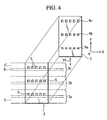
- FIG. 4 is an enlarged schematic view of an exhaust manifold section of a polymer electrolyte fuel cell stack of the presently filed embodiment. Incidentally, the positional relationship of FIG. 4 corresponds to that of FIG. 3.
- the presently filed embodiment differs from the first embodiment in that the movable member 7 is formed with the through-holes with shapes different pending upon the positions of the unit cells.
- Other component parts are similar to those of the first embodiment and, so, like component parts bear the same reference numerals to omit or simplify redundant description.
- the shapes of the through-holes 9a, 9b, 9c formed in the movable member 7 are different in association with the unit cells 2 such that the exhaust ports 6 and the through-holes 9c are aligned in shape; the through-holes 9b are shorter and smaller in area than those of the through-holes 9c; and the through-holes 9a are further shorter and smaller in area than those of the through-holes 9b.
- the setting may be made in a way to avoid the exhaust ports 6 from full alignment with the through-holes, that is, the through-holes 9a, 9b of the movable member 7, and it becomes possible to make setting such that moving the movable member 7 allows an area reduction ratio of the aperture, through which exhaust gas passes, to vary for each flow passage depending upon locations in which the flow passages are present.
- the setting is so made as to allow the surfaces areas of the through-holes 9a. 9b, 9c to be made smaller in this order than those of the associated exhaust ports 6.
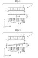
- FIG. 5 is an enlarged schematic view of a movable member of a polymer electrolyte fuel cell stack of the presently filed embodiment. Incidentally in the drawing figure, for the sake of convenience, the respective movable members are shown in an obliquely displaced status to one another.
- the presently filed embodiment differs from the second embodiment in that the movable members formed in the exhaust manifolds 5 include a plurality of component parts 7a, 7b, 7c which are independently controlled with individual moving mechanisms, respectively.
- Other component parts are similar to those of the second embodiment and, so, like component parts bear the same reference numerals to omit or simplify redundant description.
- the movable member 7a has the through-holes 9a with the shape described in connection with the second embodiment; the movable member 7b has the through-holes 9b with the shape described in connection with the second embodiment; and the movable member 7c has the through-holes 9c with the shape described in connection with the second embodiment.
- the movable members 7a, 7b, 7c are coupled to moving mechanisms with a structure as shown in FIG. 3, respectively, and moved by the associated moving mechanisms so as to appropriately overlap the associated exhaust ports 6 corresponding to operating conditions in which electric power is generated by the fuel cell stack and the flow rates of reaction gases to be supplied thereto.
- the fuel cell stack can be operated, in consideration of the characteristic shown in FIG. 15, to control the area reduction ratios at respective optimum values independently from one another for the number of pieces of the movable members corresponding to the operating condition in which electric power is generated by the fuel cell stack and the flow rates of supplied reaction gases, making it possible to control the value of the ratio between unit-cell flow-passage pressure loss and manifold pressure loss in a further minute manner within the right region as shown in FIG. 14 while enabling distributions of reaction gases to be controlled in a further minute fashion.
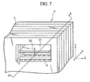
- FIG. 6 is a perspective view schematically illustrating a polymer electrolyte fuel cell stack of the presently filed embodiment
- FIG. 7 is an enlarged schematic view of an exhaust manifold section of the polymer electrolyte fuel cell stack of the presently filed embodiment
- FIG. 8 is a cross sectional view taken on line A-A of FIG. 7.
- the presently filed embodiment differs from the first embodiment in that the movable member has a structure which is disposed in the exhaust manifolds 5 and formed with a single sheet of plate with no through-hole and which is arranged to be moved closer to or away from the exhaust ports 6.
- Other component parts are similar to those of the first embodiment and, so, like component parts bear the same reference numerals to omit or simplify redundant description.
- the movable member 17 is disposed in the exhaust manifolds 5 so as to block exhaust gas from directly flowing out from the respective exhaust ports 6 to the outside of the exhaust manifolds 5, and arranged to be operative to move closer to or away from the respective exhaust ports 6 along a movable direction 20 to allow a distance L between the movable member 17 and the respective exhaust ports 6 to be variable.
- the movable member 17 may include a magnetic body or a base substrate on which the magnetic body is adhered, and the electromagnet may be located on an upper end face, along Z-axis, of the fuel cell stack 1 shown in FIG 6.
- FIG. 9 is a cross sectional view, corresponding to FIG. 8, of an exhaust manifold section of a polymer electrolyte fuel cell stack of the presently filed embodiment.
- the presently filed embodiment is similar to the fourth embodiment in that the movable member disposed in the exhaust manifolds 5 is operative to move closer to or away from the exhaust ports 6 but differs from the fourth embodiment in that the movable member is not necessarily parallel to a plane S on which the exhaust ports 6 are present.
- Other component parts are similar to those of the fourth embodiment and, so, like component parts bear the same reference numerals to omit or simplify redundant description.
- the movable member 27 is set to be operative to variably move closer to or away from the respective exhaust ports 6 along the movable direction 20 such that a distance between the movable member 27 and the respective exhaust ports 6 increases from the left to the right in FIG. 9 (L1 ⁇ L2).
- the movable member 27 is movable to allow the distance between the movable member 27 and the exhaust ports 6 of the respective unit cells 2 to be different depending upon the respective unit cells 2, moving the movable member 27 enables the setting to be made such that the area reduction ratios of the apertures through which reaction gases pass differ for each flow passage depending on the position of the flow passage.
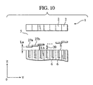
- FIG. 10 is a cross sectional view, corresponding to FIG. 8, of an exhaust manifold section of a polymer electrolyte fuel cell stack of the presently filed embodiment.
- the presently filed embodiment differs from the fifth embodiment in that the movable member disposed in the exhaust manifolds 5 is comprised with a plurality of component parts 27a, 27b, ⁇ .
- Other component parts are similar to those of the fifth embodiment and, so, like component parts bear the same reference numerals to omit or simplify redundant description.
- the movable member 27a, 27b, ⁇ are set to move closer to or away from the respective exhaust ports 6 along the movable direction 20 in the exhaust manifolds 6 such that a distance between the respective movable members and respective exhaust ports 6 variably increases from the left to the right in FIG. 10 (La ⁇ Lb) ⁇ ).
- moving the movable members 27 enables the setting to be made such that the area reduction ratios of the apertures through which reaction gases pass differ for each flow passage depending on the position of the flow passage.
- FIG. 11 is a perspective representation typically showing the polymer electrolyte fuel cell stack of the presently filed embodiment
- FIG. 12 is a flowchart illustrating a basic sequence of pressure loss control to be executed when a clogged condition occurs in a flow passage of a unit cell of the polymer electrolyte fuel cell stack shown in FIG. 11
- FIG. 13 is a flowchart illustrating a basic sequence of pressure loss control to be executed in the presence of residual hydrogen in the flow passage of the unit cell of the polymer electrolyte fuel cell stack shown in FIG. 11.
- the polymer electrolyte fuel cell stack has a structure including a clogged condition detector that detects the presence of a clogged condition resulting from condensed water in a gas flow passage inside a unit cell.
- oxidant gas such as air
- exhaust gases are exhausted, through the gas flow passages 11 inside the unit cells, from the exhaust manifold 5 to the outside.
- static pressure detectors 13a, 13b for detecting static pressure in the gas flow passage 11 of each unit cell 2 are disposed.
- the static pressure detectors 13a, 13b may be possible to use semiconductor pressure sensors each of which incorporates a silicone diaphragm formed with a bridge circuit using a piezoelectric element.
- the static pressure detector 13a is disposed in close proximity to an intermediate point of the gas flow passage 11, and the static pressure detector 13b is disposed in close proximity to an outlet of the gas flow passage 11.
- a probability occurs in which as reaction gases are progressively consumed at the downstream side at a higher rate than that of the upstream side in the gas flow passage 11 of the unit cell 2, product water resulting from reaction accumulates to cause condensed water W to form a clogged condition in the gas flow passage 11 at the downstream side thereof.
- static pressure detected values are obtained to compare these values to enable discrimination to be made that when resulting data exceeds a predetermined value, the clogged condition resulting from condensed water occurs in the gas flow passage 11.
- the detection signals delivered from the static pressure detectors 13a, 13b are applied to a controller that is not shown. Then, if the clogged condition resulting condensed water W occurs in the gas flow passage 11, gas static pressure increases at an upstream of condensed water W and a difference between the detected value of the static pressure detector 13a and the detected value of the static pressure detector 13b increases, resulting in a capability of discriminating the clogged condition.
- Map for enabling discrimination of such a static pressure difference may include data obtained by plotting the detected value of the static pressure detector 13a on the ordinate and plotting a difference between the detected value of the static pressure detector 13a and the detected value of the static pressure detector 13b on the abscissa.
- the static pressure difference based on which discrimination is made that the gas flow passage encounters the clogged condition can be determined without utilizing map that is preliminarily stored.
- the static pressure detector 13a is disposed in close proximate to the intermediate point of the gas flow passage 11 and the static pressure detector 13b is disposed in close proximate to the outlet of the gas flow passage 11 in each unit cell 2 that forms the fuel cell stack 1, and the static pressure difference is detected for each unit cell 2, thereby obtaining a representative value (including an average value, a middle value, or an intermediate value between the maximum value and the minimum value of the entire unit cells) of the static pressure difference of the fuel cell stack 1 as a whole.
- discrimination may be made that the unit cell 2, which exhibits the static pressure difference indicative of a certain value or a value exceeding a certain ratio, includes the gas flow passage encountered with the clogged condition.
- the controller operates to read the detected values of the static pressure detectors 13a, 13b for each given control cycle, such as for each 10 [mS], during operation of the fuel cell and discriminates whether the clogged condition resulting from condensed water occurs in the gas flow passage whereupon if the clogged condition occurs in the gas flow passage11, the movable member 7 is moved in a way to cause fluctuations in pressure loss to eliminate the clogged condition.
- step S10 the controller operates to read in a demanded electric current value Id required for the fuel cell stack 1.
- a demanded electric current value is able to include a value proportionate to a product resulting from an accelerator displacement value and a vehicle speed.
- step S11 the reaction gas flow rate Fg, that is, the hydrogen gas flow rate and the air flow rate are calculated, thereby operating a hydrogen flow regulator valve, an air supply compressor and an air pressure regulator valve.
- the clogged condition detector operates to read information D related to the clogged condition resulting from condensed water W in the gas flow passage 11 of each unit cell 2.
- the clogged condition detector includes the static pressure detector 13a disposed in close proximity to the intermediate point of the gas flow passage 11 and the static pressure detector 13b disposed in close proximity to the outlet, and concretely, information D related to the clogged condition is read concretely by receiving these detection signals.
- step S13 discrimination is made whether there exists the unit cell 2 whose gas flow passage 11 encounters with the clogged condition resulting from condensed water W. If discrimination is made that the unit cell 2 in which clogged condition occurs is present, operation is routed to step S14 whereas if discrimination is made that no unit cell 2 being clogged is present, operation is routed back to main routine.
- step S14 the movable member 7 is moved to variably control pressure loss in the gas flow passage 11 to cause fluctuations to occur in pressure loss for thereby pushing condensed water W toward the outlet of the gas flow passage 11 to be expelled through the exhaust port 6 to the exhaust manifold 6. And, operation is routed back to step S12 whereupon operations in step S12 and step S14 are repeatedly executed until condensed water W is completely discharged from the exhaust port 6 to the exhaust manifold 5, and when condensed water W is completely discharged, discrimination in step S13 is negative and operation is routed back to main routine.
- the cell resistance detector 14 detects alternating electric current resistance between the anode and the cathode of the unit cell 2. That is, the cell resistance detector 14 measures alternating electric current by applying alternating voltage across the anode and the cathode of each unit cell 2 and calculates alternating impedance in terms of alternating voltage and alternating electric current.
- measuring alternating impedance enables the clogged condition resulting from condensed water W to be detected.
- the discriminating value enabling discrimination
- the discriminating value associated with alternating impedance is derived from the detected value of the cell resistance detector 14 whereupon the discriminating value associated with alternating impedance is stored as map in the controller.
- alternating impedance based on which the presence of the clogged condition is discriminated, can be determined without using map that is preliminarily stored.
- the cell resistance detectors 14 are provided in the respective unit cells 2 that form the fuel cell stack 1, and alternating impedance is detected for each unit cell whereupon operation is executed to obtain a representative value (such as an average value, a middle value and an intermediate value) of alternating impedances of the entire fuel cell stacks 1.
- discrimination may be made that the clogged condition occurs in the gas flow passage 11 of the unit cell 2 when this unit cell 2 exhibits a certain value or a value that decreases by a rate exceeding a certain ratio in terms of such a representative value.
- the cell voltage detector 15 serves to detect a voltage across the anode and the cathode of the unit cell 2, and larger the amount of condensed water W in the gas flow passage 11 is, the lower will be the voltage of the unit cell 2. Accordingly, measuring the cell voltage of the unit cell 2 enables the clogged condition resulting from condensed water W to be detected.
- the discriminating value enabling discrimination
- a condition is preliminarily and experimentally created for enabling the clogged condition resulting from condensed water W to be discriminated
- a voltage discriminating value based on which discrimination is made that the clogged condition occurs, is derived from the detected value of the cell voltage detector 15 whereupon the voltage discriminating value is stored as map in the controller.
- the cell voltage based on which the presence of the clogged condition for the gas flow passage of each unit cell 2 is discriminated, can be determined without using map that is preliminarily stored.
- the cell voltage detectors 15 are provided in the respective unit cells 2 that form the fuel cell stack 1, and the cell voltage is detected for each unit cell whereupon operation is executed to obtain a representative value (such as an average value, a middle value and an intermediate value) of the cell voltages of the fuel cell stack 1 as a whole.
- discrimination may be made that the clogged condition occurs in the gas flow passage 11 of the unit cell 2 when this unit cell 2 exhibits a certain value or a value that decreases by a rate exceeding a certain ratio in terms of such a representative value.
- the temperature detector 16 serves to detect the temperature of a position close proximity to the inlet of the gas flow passage 11 of the unit cell 2, that is, a position in the vicinity of the supply manifold 4 of the gas flow passage 11.
- the clogged condition resulting from condensed water W occurs in the gas flow passage 11 of the unit cell 2 at an outlet thereof at an increased frequency and, hence, the unit cell 2 generates electric power in a concentrated area near the inlet of the gas flow passage 11. From this phenomenon, with the unit cell 2 in which the clogged condition occurs, the temperature in close proximity to the inlet of the gas flow passage 11 becomes higher than that experienced during a normal condition, and using the temperature detector 16 to detect this temperature enables the clogged condition to be discriminated.
- the discriminating value enabling discrimination
- the discriminating value is derived in such a way that a condition is preliminarily and experimentally created for enabling the clogged condition resulting from condensed water W to be discriminated to allow a voltage discriminating value, based on which discrimination is made that the clogged condition occurs, to be derived from the detected value of the temperature detector 16 whereupon the voltage discriminating value is stored as map in the controller.
- the cell voltage based on which discrimination is made for each unit cell 2 that the clogged condition occurs in the gas flow passage 11, can also be determined without using map that is preliminarily stored.
- the temperature detectors 16 are provided in the respective unit cells 2 that form the fuel cell stack 1, and the temperatures are detected for each unit cell whereupon operation is executed to obtain a representative value (such as an average value, a middle value and an intermediate value) of the temperatures of the fuel cell stack 1 as a whole.
- discrimination may be made that the clogged condition occurs in the gas flow passage 11 of the unit cell 2 when this unit cell 2 exhibits a certain value or a value that decreases by a rate exceeding a certain ratio in terms of such a representative value.
- each gas flow passage to be objective is the fuel gas (hydrogen) flow passage that is representatively shown as the flow passage 11 in FIG. 11 for the sake of explanation.
- the cell voltage detector 15 detects the voltage of each unit cell 2 during start-up of the fuel cell system and derives residual hydrogen quantity ratio distribution of each unit cell 2 within the stack 1 from a distribution pattern in the cell voltages of the fuel cell stack 1. The larger the residual hydrogen quantity in the fuel gas flow passage 11 of the unit cell 2 is, the higher will be the cell voltage to be detected by the cell voltage detector 15.
- Pressure loss control to be executed based on residual hydrogen in the flow passage 11 inside the fuel cell 2, is explained below with reference to FIG. 13.
- the controller executes such control during start-up of the fuel cell system.
- step S20 non-load voltage Vi of each unit cell 2 is detected by the cell voltage detector 15 and read into the controller.
- next step S21 the controller calculates a fluctuation ⁇ Vi from non-load voltage detected values Vi of the respective unit cells 2 and makes discrimination whether the fluctuation ⁇ Vi is equal to or exceeds a predetermined value PD.
- a mean value V ⁇ and a variance V ⁇ of the non-load voltage detected values Vi of the respective unit cells 2 of the fuel cell stack 1 as a whole are calculated and if the variance V ⁇ of the non-load voltage detected values Vi is equal to or exceeds a predetermined value, then, discrimination is made that the fluctuation ⁇ Vi is equal to or exceeds the predetermined value PD.
- this discriminating value results from values that are effective for adequately suppressing deterioration in the fuel cell stack 1 and obtained through preliminary simulation and experimental tests.
- step S21 if discrimination is made that the fluctuation ⁇ Vi is equal to or exceeds the predetermined value PD, operation is routed to step S22 where the movable member 7 is controlled such that pressure loss in the fuel gas flow passage 11 of the fuel cell 2, with a low level in the non-load voltage detected values Vi, decreases in accordance with the non-load voltage detected values Vi, that is, such that the smaller the residual hydrogen quantity in a unit cell among the plurality of unit cells is, the larger a quantity of hydrogen is supplied to this unit cell.
- step S23 supply of hydrogen, serving as fuel, is commenced and, then, the fuel cell stack 1 shifts to a normal operation control mode.
- step S23 if discrimination is made that the fluctuation ⁇ Vi is less than the predetermined value PD, operation is routed to step S23 without executing step S22.
Landscapes
- Life Sciences & Earth Sciences (AREA)
- Engineering & Computer Science (AREA)
- Manufacturing & Machinery (AREA)
- Sustainable Development (AREA)
- Sustainable Energy (AREA)
- Chemical & Material Sciences (AREA)
- Chemical Kinetics & Catalysis (AREA)
- Electrochemistry (AREA)
- General Chemical & Material Sciences (AREA)
- Fuel Cell (AREA)
Applications Claiming Priority (2)
| Application Number | Priority Date | Filing Date | Title |
|---|---|---|---|
| JP2003118415 | 2003-04-23 | ||
| JP2003118415 | 2003-04-23 |
Publications (1)
| Publication Number | Publication Date |
|---|---|
| EP1511115A1 true EP1511115A1 (de) | 2005-03-02 |
Family
ID=33296363
Family Applications (1)
| Application Number | Title | Priority Date | Filing Date |
|---|---|---|---|
| EP04009577A Withdrawn EP1511115A1 (de) | 2003-04-23 | 2004-04-22 | Polymerelektrolyt Brennstoffzellenstapel und damit zusammenhängende Methode zur Druckabfallüberprüfung |
Country Status (2)
| Country | Link |
|---|---|
| US (1) | US20040214062A1 (de) |
| EP (1) | EP1511115A1 (de) |
Families Citing this family (8)
| Publication number | Priority date | Publication date | Assignee | Title |
|---|---|---|---|---|
| JP4924790B2 (ja) * | 2005-06-30 | 2012-04-25 | トヨタ自動車株式会社 | 燃料電池システム |
| JP2007048507A (ja) * | 2005-08-08 | 2007-02-22 | Nippon Soken Inc | 燃料電池システム |
| JP2008041646A (ja) * | 2006-07-11 | 2008-02-21 | Canon Inc | 燃料電池システム、燃料電池の活性化処理方法 |
| US20080192442A1 (en) * | 2007-02-13 | 2008-08-14 | Lupton Michael B | Dual Hinge Bracket |
| US7816050B2 (en) | 2007-02-16 | 2010-10-19 | Daimler Ag | Unit cell header flow enhancement |
| TWI395367B (zh) * | 2010-03-18 | 2013-05-01 | Univ Nat Central | Fuel cell flow adjustment mechanism |
| WO2011155930A1 (en) * | 2010-06-09 | 2011-12-15 | Empire Technology Development Llc | Adjustable pressure microreactor |
| JP7302528B2 (ja) * | 2020-05-15 | 2023-07-04 | トヨタ自動車株式会社 | 燃料電池システム |
Citations (3)
| Publication number | Priority date | Publication date | Assignee | Title |
|---|---|---|---|---|
| WO2001001508A1 (en) * | 1999-06-25 | 2001-01-04 | Ballard Power Systems Inc. | Method and apparatus for operating an electrochemical fuel cell with periodic reactant starvation |
| JP2001202984A (ja) * | 2000-01-19 | 2001-07-27 | Toshiba Corp | 固体高分子型燃料電池スタック |
| US20010014415A1 (en) * | 2000-02-16 | 2001-08-16 | Nissan Motor Co., Ltd. | Fuel cell system and method |
Family Cites Families (2)
| Publication number | Priority date | Publication date | Assignee | Title |
|---|---|---|---|---|
| JP3775618B2 (ja) * | 1997-06-30 | 2006-05-17 | アイシン精機株式会社 | 燃料電池 |
| US6759016B2 (en) * | 2000-11-30 | 2004-07-06 | Ballard Power Systems Inc. | Compact multiple tube steam reformer |
-
2004
- 2004-04-21 US US10/828,273 patent/US20040214062A1/en not_active Abandoned
- 2004-04-22 EP EP04009577A patent/EP1511115A1/de not_active Withdrawn
Patent Citations (3)
| Publication number | Priority date | Publication date | Assignee | Title |
|---|---|---|---|---|
| WO2001001508A1 (en) * | 1999-06-25 | 2001-01-04 | Ballard Power Systems Inc. | Method and apparatus for operating an electrochemical fuel cell with periodic reactant starvation |
| JP2001202984A (ja) * | 2000-01-19 | 2001-07-27 | Toshiba Corp | 固体高分子型燃料電池スタック |
| US20010014415A1 (en) * | 2000-02-16 | 2001-08-16 | Nissan Motor Co., Ltd. | Fuel cell system and method |
Non-Patent Citations (3)
| Title |
|---|
| PATENT ABSTRACTS OF JAPAN vol. 0133, no. 54 (E - 802) 8 August 1989 (1989-08-08) * |
| PATENT ABSTRACTS OF JAPAN vol. 1996, no. 12 26 December 1996 (1996-12-26) * |
| PATENT ABSTRACTS OF JAPAN vol. 2000, no. 24 11 May 2001 (2001-05-11) * |
Also Published As
| Publication number | Publication date |
|---|---|
| US20040214062A1 (en) | 2004-10-28 |
Similar Documents
| Publication | Publication Date | Title |
|---|---|---|
| CA2647802C (en) | Fuel cell with hydrogen leak detection | |
| EP2269257B1 (de) | Brennstoffzellensystem und verfahren zum betreiben einer brennstoffzelle | |
| CN101868879B (zh) | 燃料电池系统 | |
| US7348083B2 (en) | Fuel cell system | |
| US7354670B2 (en) | Fuel cell with fuel gas adjustment mechanism | |
| EP2800184A1 (de) | Brennstoffzellensystem | |
| EP1511115A1 (de) | Polymerelektrolyt Brennstoffzellenstapel und damit zusammenhängende Methode zur Druckabfallüberprüfung | |
| US8815463B2 (en) | Fuel cell system and its control method | |
| JP2011044290A (ja) | 燃料電池システムおよび燃料電池システムの運転方法 | |
| US9853316B2 (en) | Fuel cell system | |
| US7442456B2 (en) | Current control for parallel fuel cell stacks | |
| US6682835B2 (en) | Method and apparatus for increasing the operational efficiency of a fuel cell power plant | |
| JP4529373B2 (ja) | 燃料電池および燃料電池の運転方法 | |
| EP2669978B1 (de) | Brennstoffzellensystem | |
| US20050208349A1 (en) | Method for detecting undersupply of fuel gas and method for controlling fuel cell | |
| JP2004342596A (ja) | 固体高分子型燃料電池スタック | |
| JP2011258396A (ja) | 燃料電池システム | |
| US9455460B2 (en) | Method of controlling and maximizing the electric efficiency and the power output of a fuel cell | |
| JP2006302578A (ja) | 燃料電池の運転方法及び燃料電池システム | |
| WO2010058704A1 (ja) | 燃料電池システムの運転方法 | |
| CN114628746B (zh) | 燃料电池系统 | |
| JP4935446B2 (ja) | 燃料電池システム | |
| JP2014142997A (ja) | 燃料電池システム | |
| JP2023127704A (ja) | 燃料電池システム | |
| JP5385525B2 (ja) | 燃料電池システム |
Legal Events
| Date | Code | Title | Description |
|---|---|---|---|
| PUAI | Public reference made under article 153(3) epc to a published international application that has entered the european phase |
Free format text: ORIGINAL CODE: 0009012 |
|
| 17P | Request for examination filed |
Effective date: 20040422 |
|
| AK | Designated contracting states |
Kind code of ref document: A1 Designated state(s): AT BE BG CH CY CZ DE DK EE ES FI FR GB GR HU IE IT LI LU MC NL PL PT RO SE SI SK TR |
|
| AX | Request for extension of the european patent |
Extension state: AL HR LT LV MK |
|
| AKX | Designation fees paid |
Designated state(s): DE FR GB |
|
| 17Q | First examination report despatched |
Effective date: 20070605 |
|
| STAA | Information on the status of an ep patent application or granted ep patent |
Free format text: STATUS: THE APPLICATION HAS BEEN WITHDRAWN |
|
| 18W | Application withdrawn |
Effective date: 20070830 |