EP1511114A2 - Brennstoffzellenanlage - Google Patents
Brennstoffzellenanlage Download PDFInfo
- Publication number
- EP1511114A2 EP1511114A2 EP04255173A EP04255173A EP1511114A2 EP 1511114 A2 EP1511114 A2 EP 1511114A2 EP 04255173 A EP04255173 A EP 04255173A EP 04255173 A EP04255173 A EP 04255173A EP 1511114 A2 EP1511114 A2 EP 1511114A2
- Authority
- EP
- European Patent Office
- Prior art keywords
- fuel
- layer
- layers
- anode
- migration
- Prior art date
- Legal status (The legal status is an assumption and is not a legal conclusion. Google has not performed a legal analysis and makes no representation as to the accuracy of the status listed.)
- Withdrawn
Links
Images



Classifications
-
- H—ELECTRICITY
- H01—ELECTRIC ELEMENTS
- H01M—PROCESSES OR MEANS, e.g. BATTERIES, FOR THE DIRECT CONVERSION OF CHEMICAL ENERGY INTO ELECTRICAL ENERGY
- H01M8/00—Fuel cells; Manufacture thereof
- H01M8/10—Fuel cells with solid electrolytes
- H01M8/1007—Fuel cells with solid electrolytes with both reactants being gaseous or vaporised
-
- H—ELECTRICITY
- H01—ELECTRIC ELEMENTS
- H01M—PROCESSES OR MEANS, e.g. BATTERIES, FOR THE DIRECT CONVERSION OF CHEMICAL ENERGY INTO ELECTRICAL ENERGY
- H01M8/00—Fuel cells; Manufacture thereof
- H01M8/02—Details
- H01M8/0271—Sealing or supporting means around electrodes, matrices or membranes
-
- H—ELECTRICITY
- H01—ELECTRIC ELEMENTS
- H01M—PROCESSES OR MEANS, e.g. BATTERIES, FOR THE DIRECT CONVERSION OF CHEMICAL ENERGY INTO ELECTRICAL ENERGY
- H01M8/00—Fuel cells; Manufacture thereof
- H01M8/10—Fuel cells with solid electrolytes
- H01M8/1097—Fuel cells applied on a support, e.g. miniature fuel cells deposited on silica supports
-
- H—ELECTRICITY
- H01—ELECTRIC ELEMENTS
- H01M—PROCESSES OR MEANS, e.g. BATTERIES, FOR THE DIRECT CONVERSION OF CHEMICAL ENERGY INTO ELECTRICAL ENERGY
- H01M8/00—Fuel cells; Manufacture thereof
- H01M8/24—Grouping of fuel cells, e.g. stacking of fuel cells
- H01M8/241—Grouping of fuel cells, e.g. stacking of fuel cells with solid or matrix-supported electrolytes
- H01M8/2418—Grouping by arranging unit cells in a plane
-
- H—ELECTRICITY
- H01—ELECTRIC ELEMENTS
- H01M—PROCESSES OR MEANS, e.g. BATTERIES, FOR THE DIRECT CONVERSION OF CHEMICAL ENERGY INTO ELECTRICAL ENERGY
- H01M8/00—Fuel cells; Manufacture thereof
- H01M8/24—Grouping of fuel cells, e.g. stacking of fuel cells
- H01M8/2457—Grouping of fuel cells, e.g. stacking of fuel cells with both reactants being gaseous or vaporised
-
- Y—GENERAL TAGGING OF NEW TECHNOLOGICAL DEVELOPMENTS; GENERAL TAGGING OF CROSS-SECTIONAL TECHNOLOGIES SPANNING OVER SEVERAL SECTIONS OF THE IPC; TECHNICAL SUBJECTS COVERED BY FORMER USPC CROSS-REFERENCE ART COLLECTIONS [XRACs] AND DIGESTS
- Y02—TECHNOLOGIES OR APPLICATIONS FOR MITIGATION OR ADAPTATION AGAINST CLIMATE CHANGE
- Y02E—REDUCTION OF GREENHOUSE GAS [GHG] EMISSIONS, RELATED TO ENERGY GENERATION, TRANSMISSION OR DISTRIBUTION
- Y02E60/00—Enabling technologies; Technologies with a potential or indirect contribution to GHG emissions mitigation
- Y02E60/30—Hydrogen technology
- Y02E60/50—Fuel cells
Definitions
- the present invention relates to a fuel-cell device utilizing surface-migration on organic solid, and more particularly to a fuel-cell device utilizing surface-migration on organic solid comprising a cathode layer and an anode layer formed a prescribed distance apart on one surface of a solid organic substrate, wherein provisions are made to supply a fuel to the anode layer via a fuel supply layer formed thereon and to supply air to the cathode layer, thereby accomplishing a simple structure obviating the need to hermetically seal the fuel-cell device, and thus achieving a compact and thin construction while, at the same time, achieving a lower operating temperature for power generation.
- fuel cells have been developed and commercially implemented as a low-pollution power generating means to replace traditional power generation such as thermal power generation, or as an electric energy source for electric vehicles that replaces the internal combustion engine which uses gasoline or the like as the fuel.
- traditional power generation such as thermal power generation
- electric energy source for electric vehicles that replaces the internal combustion engine which uses gasoline or the like as the fuel.
- Fuel cells can be classified into various types according to the method of power generation, one being the type of fuel cell that uses a solid electrolyte.
- a fuel cell that uses a calcined structure made of yttria (Y 2 O 3 )-doped stabilized zirconia as an oxygen ion conducting solid electrolyte layer.
- This type of fuel cell comprises a cathode layer formed on one surface of the solid electrolyte layer and an anode layer on the opposite surface thereof, and oxygen or an oxygen-containing gas is fed to the cathode layer, while a fuel gas such as methane is fed to the anode layer.
- the oxygen (O 2 ) fed to the cathode layer is converted into oxygen ions (O 2- ) at the boundary between the cathode layer and the solid electrolyte layer, and the oxygen ions are conducted through the solid electrolyte layer into the anode layer where the ions react with the fuel gas, for example, a methane gas (CH 4 ), fed to the anode layer, the end products of the reaction being water (H 2 O) and carbon dioxide (CO 2 ).
- the fuel gas for example, a methane gas (CH 4 )
- CH 4 methane gas
- CO 2 carbon dioxide
- the cathode layer and the anode layer are electrically connected by a lead wire, the electrons in the anode layer flow into the cathode layer via the lead wire, and the fuel cell thus generates electricity.
- the operating temperature of this type of fuel cell is about 1000°C.
- this type of fuel cell requires the provision of separate chambers, one being an oxygen or oxygen-containing gas supply chamber on the cathode layer side and the other a fuel gas supply chamber on the anode layer side; furthermore, as the fuel cell is exposed to oxidizing and reducing atmospheres at high temperatures, it has been difficult to increase the durability of the fuel cell.
- a fuel cell of the type that comprises a cathode layer and an anode layer formed on opposite surfaces of a solid electrolyte layer, and that generates an electromotive force between the cathode layer and the anode layer by placing the fuel cell in a mixed fuel gas consisting of a fuel gas, for example, a methane gas, and an oxygen gas.
- a fuel gas for example, a methane gas, and an oxygen gas.
- the principle of generating an electromotive force between the cathode layer and the anode layer is the same for this type of fuel cell as for the above-described separate-chamber type fuel cell but, as the whole fuel cell can be exposed to substantially the same atmosphere, the fuel cell can be constructed as a single-chamber type cell to which the mixed fuel gas is supplied, and this serves to increase the durability of the fuel cell.
- the fuel-cell device described above is of the type that is constructed by housing individual fuel cells in a single chamber; on the other hand, an apparatus has been proposed that does not require the provision of a special chamber, and that generates electricity by placing a solid electrolyte fuel cell in or near a flame and thereby holding the solid electrolyte fuel cell at its operating temperature.
- the fuel cell used in this electric power generating apparatus comprises a zirconia solid electrolyte layer formed in a tubular structure, an anode layer as a fuel electrode formed on the outer circumference of the tubular structure, and a cathode layer as an air electrode formed on the inner circumference of the tubular structure.
- This solid electrolyte fuel cell is operated with the anode layer exposed to a reducing flame portion of a flame generated from a combustion apparatus to which the fuel gas is supplied.
- radical components, etc. present in the reducing flame are utilized as the fuel, while air is supplied by convection or diffusion to the cathode layer inside the tubular structure, and the fuel cell thus generates electricity.
- Such a fuel-cell device is proposed, for example, in Japanese Unexamined Patent Publication No. 6-196176.
- the solid electrolyte layer functions as an oxygen ion conductor, and the oxygen ions conducted through the solid electrolyte layer react with fuel species to generate an electromotive force.
- a fuel cell is proposed that operates on the principle that an electromotive force can be generated by the two reactant species migrating over the surface of an insulating substrate and reacting with each other.
- two electrodes are arranged in close proximity to each other on the same surface of an insulating substrate, and both electrodes are exposed to a mixed gas of oxygen and hydrogen.
- oxygen ions are formed by chemisorption and, at the other electrode, hydrogen ions are formed by chemisorption; then, the thus formed oxygen ions and hydrogen ions migrate over the surface of the insulating substrate and react with each other. It is claimed that, in this way, an electromotive force can be generated between the two electrodes.
- the earlier described single-chamber fuel-cell device obviates the necessity of strictly separating the fuel and the air, as was the case with conventional solid electrolyte fuel-cell devices, but has to employ an explosion-proof, hermetically sealed construction. Further, to increase the electromotive force, a plurality of plate-like solid electrolyte fuel cells need to be stacked and, since they are operated at high temperatures, an interconnect material having high heat resistance and high electrical conductivity must be used to electrically connect the plurality of plate-like solid electrolyte fuel cells. As a result, the single-chamber fuel-cell device constructed from a stack of plate-like solid electrolyte fuel cells has the problem that the construction is not only large but also costly.
- this type of single-chamber fuel-cell device has had the problem that it requires a significant startup time and hence extra trouble to operate; that is, with this type of fuel-cell device, it has not been possible to generate electricity in a simple manner.
- the oxygen ion conducting solid electrolyte fuel-cell device formed in a tubular structure employs the fuel cell of the type that directly utilizes a flame; this type of fuel cell has the characteristic of being an open type, the solid electrolyte fuel cell not needing to be housed in a hermetically sealed container.
- this type of fuel cell can have a reduced startup time, is simple in structure, and is therefore advantageous when it comes to reducing the size, weight, and cost of the fuel cell, and it can be said that this fuel cell is a handy power plant.
- this type of fuel cell can be incorporated in a conventional combustion apparatus or an incinerator or the like, and is thus expected to be used as an electricity supply device.
- the earlier cited paper provides no more than a report that the proposed fuel cell can theoretically generate an electromotive force, and this type of fuel cell has not been implemented in practice for such reasons as: it has been difficult to form the two electrodes close enough together; an electrode material that can form a specific reactant species by selectively chemisorbing one of the reaction components is not easily found; the insulating substrate must have good desorption for the reaction product formed on its surface; and experiments must be performed outside the explosion range of the mixed gas.
- a fuel-cell device utilizing surface-migration on organic solid in which a cathode layer and an anode layer are arranged parallel to each other on one surface of a solid organic substrate, wherein provisions are made to supply air to the cathode layer and to supply a fluid fuel directly to the anode layer, thereby achieving reductions in the size and cost of the fuel-cell device while, at the same time, achieving lower operating temperature for power generation.
- the present invention provides a fuel-cell device utilizing surface-migration on organic solid in which a cathode layer, to which air is supplied, and an anode layer, to which a fluid fuel is supplied, are arranged on one surface of a solid organic substrate in such a manner as to oppose each other across a given surface region of the solid organic substrate, wherein a fuel supply layer for supplying the fluid fuel to the surface region via the anode layer is provided in contacting relationship with the anode layer.
- the solid organic substrate is formed from a material selected from the group consisting of a polyethylene terephthalate resin, a polyester resin, an epoxy resin, a polyimide resin, a polyvinylidene chloride resin, and a polyethylene resin, wherein the solid organic substrate can be formed on a reinforcing substrate, a semiconductor substrate, or a heat-exchange substrate.
- the cathode layer and the anode layer are porous layers each formed in the shape of a strip.
- the cathode layer is a porous layer formed in the shape of a strip and the anode layer is a metal powder filled layer formed in the shape of a strip
- the cathode layer is a porous layer formed in the shape of a strip and the anode layer is a metal plate formed in the shape of a strip.
- the anode layer is formed from a material selected from the group consisting of rhenium, tungsten, nickel, molybdenum, and copper, while the cathode layer is formed from a material selected from the group consisting of samarium strontium cobaltite, lanthanum strontium cobaltite, and lanthanum strontium manganite.
- the fuel supply layer is placed along the length of the anode layer in contacting relationship with an upper surface or a side surface of the anode layer so that the fluid fuel permeates from one end of the fuel supply layer and is supplied to the surface region, wherein the fuel supply layer is formed from an inorganic powder filled material or an inorganic fiber aggregate; further, the fuel supply layer has, on a surface thereof opposite from the anode layer, a cover layer for preventing the fluid fuel from scattering or evaporating, wherein the cover layer can be formed in such a manner as to cover all surfaces of the fuel supply layer except the surface thereof contacting the anode layer.
- a plurality of cathode layers and a plurality of anode layers are formed on the solid organic substrate, wherein the plurality of cathode layers extending from a common cathode layer and the plurality of anode layers extending from a common anode layer are arranged parallel to each other in interlocking comb-shaped patterns on the solid organic substrate.
- a plurality of common cathode layers and a plurality of common anode layers are provided, wherein the common cathode layers and the common anode layers are respectively connected together electrically and the common cathode layers and the common anode layers are connected in parallel; alternatively, a plurality of common cathode layers and a plurality of common anode layers are provided, wherein the common cathode layers and the common anode layers are alternately connected electrically and the common cathode layers and the common anode layers are connected in series.
- a plurality of common cathode layers and a plurality of common anode layers are provided, wherein the common cathode layers and the common anode layers are respectively connected together electrically, forming a plurality of parallel connection groups of the common cathode layers and the common anode layers, and the plurality of parallel connection groups are connected in series.
- the fuel supply layer is placed between two adjacent ones of the anode layers in contacting relationship with side surfaces of the adjacent anode layers so that the fluid fuel permeates from one end of the fuel supply layer and is supplied to the surface region via each of the adjacent anode layers, wherein each of the cathode layers is disposed on either side of the anode layers opposite from the fuel supply layer in such a manner as to sandwich the surface region therebetween, and a cover layer is provided that covers the upper surfaces of the adjacent anode layers as well as the fuel supply layer placed between the anode layers.
- Embodiments of a fuel-cell device utilizing surface-migration on organic solid according to the present invention will be described below with reference to the drawings. However, before proceeding to the description of the fuel-cell devices utilizing surface-migration on organic solid of the embodiments according to the present invention, prior art solid electrolyte fuel-cell devices related to the fuel-cell devices utilizing surface-migration on organic solid of the embodiments will be described in order to clarify the features and advantages of the respective embodiments.
- FIGs 9A and 9B show the structures of the single-chamber fuel-cell devices proposed in the prior art.
- the fuel-cell device shown in Figure 9A has a structure in which individual fuel cells each containing a solid electrolyte layer are stacked one on top of another with each cell oriented parallel to the flow direction of the mixed fuel gas.
- Each fuel cell comprises a solid electrolyte layer 1 of a closely compacted structure and a cathode layer 2 and an anode layer 3 as porous layers formed on opposite surfaces of the solid electrolyte layer 1, and the plurality of fuel cells C1 to C4 of identical structure are stacked in a ceramic container 4. Then, the fuel cells are hermetically sealed in the container 4, after adding fillers 7 and 8, by closing them with end plates 9 and 10.
- the container 4 is provided with a supply pipe 5 for supplying the mixed fuel gas containing oxygen and a fuel such as methane and an exhaust pipe 6 for ejecting the exhaust gas.
- Vacant spaces in the container 4, where the mixed fuel gas and the exhaust gas flow i.e., the areas in the container 4 other than the area occupied by the fuel cells, are filled with the fillers 7 and 8, and a suitable gap is provided therebetween, thereby preventing the mixed fuel gas from igniting even when the mixed fuel gas within the ignitability limit is contained therein when the fuel-cell device is operated.
- each fuel cell comprises a solid electrolyte layer 1 of a porous structure and a cathode layer 2 and an anode layer 3 as porous layers formed on opposite surfaces of the solid electrolyte layer 1, and the plurality of fuel cells C1 to C5 of identical structure are stacked in the container 4.
- An oxygen ion conducting solid electrolyte fuel-cell device that directly utilizes a flame has been developed as a fuel-cell device that can be used as a handy power plant without requiring a hermetically sealed structure.
- this type of solid electrolyte fuel-cell device unlike the fuel-cell device that uses separate chambers according to the prior art, the oxygen to be fed to the cathode layer and the fuel to be fed to the anode layer can be reliably separated despite its open type construction but, as the solid electrolyte layer is formed in the shape of a tube, the flame has not been able to be applied efficiently to the anode layer formed on the outer circumference of the solid electrolyte layer, and therefore, its power generation efficiency has been low.
- the fuel should be supplied uniformly over the entire surface of the anode layer.
- a fluid fuel relatively easy to handle is employed as the fuel, and a fuel supply layer is provided that allows the fluid fuel to permeate therethrough so as to be fed uniformly over the entire surface of the anode layer.
- a fuel that easily permeates through the fuel supply layer is suitable for use as the fluid fuel and examples include hydrogen, vapor-phase hydrocarbons, etc. in the case of a gaseous fuel, and liquid-phase hydrocarbons, alcohol, ketone, ester, ether, etc. in the case of a liquid fuel.
- the anode layer of each fuel cell is formed from a ceramic having electrical conductivity or a metal having oxidation resistance to the mixed fuel gas supplied at the operating temperature of the fuel cell; here, it has been proposed to increase the power generation performance by adding a transition metal or its oxide to the anode layer, the transition metal being selected from the group consisting of rhodium (Rh), platinum (Pt), ruthenium (Ru), palladium (Pd), rhenium (Re), and iridium (Ir).
- the anode layer of the oxygen ion conducting solid electrolyte fuel cell from a transition metal selected from the group consisting of rhodium (Rh), platinum (Pt), ruthenium (Ru), palladium (Pd), rhenium (Re), and iridium (Ir). Further, as it is required that the anode layer formed from such a transition metal be permeable to the fluid fuel supplied, it has been found that the anode layer should be formed from a porous layer or a layer filled with powder particles.
- the anode layer can be formed on the solid electrolyte layer by sputtering or evaporating a rhenium metal; here, since a rhenium powder with a purity of 99.995% and a grain size of 100 to 325 mesh (manufactured by Aldrich) is commercially available, this rhenium powder can be conveniently used as-is as the anode layer.
- the rhenium powder has the property that its electrical conductivity is high even in a powder state; therefore, the rhenium powder is advantageous because the internal resistance of the anode layer itself can be reduced even if the rhenium metal powder is used, as-is, as the anode layer.
- rhenium in the powder state has the advantage that the specific surface area increases, increasing the number of points at which the powder particles contact each other.
- the catalytic activity can be enhanced because the contact condition of particle surfaces improves and the specific surface area increases; therefore, it has been confirmed that not only rhenium, but also other transition metals, can also be used in a powder state to form the anode layer.
- a porous anode layer can be easily formed by preparing a metal powder in the form of a paste and sintering the paste but, in the case of the rhenium metal powder, it is known that when it is heated, for example, in the atmosphere, if the temperature exceeds about 400°C, its weight decreases, and also that when it is heated in a nitrogen atmosphere, if the temperature exceeds about 418°C, its weight decreases.
- the rhenium metal powder is prepared in the form of a paste and the paste is sintered, the rhenium metal vaporizes and the anode layer cannot be formed; therefore, it can be understood that the rhenium metal should be used in a powder form.
- the operating temperature for power generation was about 1000°C; on the other hand, when the anode layer is formed from the rhenium metal, it can be understood from the above property of the rhenium metal that the fuel cell should be operated for power generation at temperatures of about 300°C or lower, considering variations in heat balance, and preferably at temperatures of about 200°C or lower. This means that the operating temperature for power generation can be reduced in the case of the solid electrolyte fuel cell whose anode layer is formed from a rhenium metal powder. For the transition metals other than rhenium, it was confirmed that an electromotive force appears between the cathode layer and the anode layer at 300°C or lower or even at room temperature.
- the embodiments of the present invention are each directed to the provision of a fuel-cell device utilizing surface-migration on organic solid which uses a solid organic substrate as the substrate, and in which the cathode layer, which directly contacts air, and the anode layer, to which a fluid fuel is directly supplied from the fuel supply layer, are arranged in parallel and in close proximity to each other on one surface of the solid organic substrate and an electromotive force is generated between the cathode layer and the anode layer.
- This configuration obviates the need to place the fuel cells in an explosive atmosphere of the mixed gas and also the need to house them in a hermetically sealed chamber. Further, as the cathode layer can be maintained in an oxygen-rich condition, and the anode layer in a fuel-rich condition, the catalytic activity of each layer can be enhanced. Moreover, when a transition metal such as rhenium is used for the anode layer, the operating temperature for power generation can be reduced compared with the prior art fuel cells, and it becomes possible to generate electricity even at room temperature.
- the power generation operating temperature of the fuel-cell device can be reduced; as a result, there is no need to take into account possible cracking of the solid layer due to thermal history, nor is it necessary to provide a hermetically sealed construction, and an inexpensive and handy fuel-cell device can thus be achieved.
- the power generation operating temperature is lowered, it becomes easier to use a fluid fuel such as hydrogen, vapor-phase hydrocarbons, liquid-phase hydrocarbons, alcohol, ketone, ester, ether, etc. as the fuel for the fuel-cell device; furthermore, the substrate need not necessarily be formed from a heat resistant material, allowing the use of widely available inexpensive materials. Further, by using an organic material for the substrate, a flexible fuel-cell device can be achieved.
- Figure 1A a first embodiment of a fuel-cell device utilizing surface-migration on organic solid according to the present invention, which is constructed based on the above-stated reason, will be shown in Figure 1A.
- Figure 1A the structure of the fuel-cell device utilizing surface-migration on organic solid is schematically shown in cross section.
- Figure 2 shows a top plan view of the fuel-cell device utilizing surface-migration on organic solid; a portion of the cross section taken along line A-A in the figure corresponds to the cross section shown in Figure 1A.
- strip-shaped anode layers (fuel electrodes) 3 1 and 3 2 are formed in parallel and in close proximity to the respective sides of a strip-shaped cathode layer (air electrode) 2 on one surface (in Figure 1A, on the upper surface) of a solid organic substrate 1 having a prescribed thickness.
- a strip-shaped cathode layer (air electrode) 2 on one surface (in Figure 1A, on the upper surface) of a solid organic substrate 1 having a prescribed thickness.
- Fuel supply layers 11 1 and 11 2 are placed on the upper surfaces of the respective anode layers 3 1 and 3 2 .
- the fuel supply layers 11 1 and 11 2 are provided to supply a fluid fuel directly to the entire surfaces of the respective anode layers; the fluid fuel is fed through one end of each fuel supply layer, permeates through the fuel supply layer while being diffused therein, and is supplied to the anode layer.
- the cathode layers and the anode layers are arranged in parallel and in close proximity to each other on the surface of the solid organic substrate 1, ion conducting surface regions are formed between the cathode layer and its adjacent anode layers, thus forming fuel cells C1 and C2. Since these fuel cells are placed in an open air space, the cathode layer 2 is in an oxygen-rich condition, so that oxygen ions are formed there and supplied to the surface regions on the substrate 1.
- the fuel is supplied from the fuel supply layers 11 1 and 11 2 to the respective anode layers 3 1 and 3 2 , where the fuel is activated to form fuel species which react with the oxygen ions that migrated over the surface regions. With this reaction, an electromotive force is generated between the cathode layer and the respective anode layers.
- FIG 2 which shows the top plan view of the fuel-cell device utilizing surface-migration on organic solid
- the anode layers are hidden from view by the fuel supply layers formed thereon, but it will be noted that surface regions are formed between each cathode layer and the anode layers on both sides thereof, forming a plurality of fuel cells.
- the cathode layers and the anode layers are arranged in interlocking comb-shaped patterns with alternate layers connected together at one end, the plurality of fuel cells are connected in parallel to form one fuel-cell device.
- FIG 1B shows another specific example of the fuel-cell device utilizing surface-migration on organic solid shown in Figure 1A.
- the basic structure of the fuel-cell device utilizing surface-migration on organic solid shown in Figure 1B is the same as that shown in Figure 1A, except that a cover layer is formed on the upper surface of each fuel supply layer.
- the cover layers 12 1 and 12 2 are formed on the surfaces of the respective fuel supply layers 11 1 and 11 2 opposite from the surfaces thereof contacting the anode layers 3 1 and 3 2 . This reduces the possibility of the fluid fuel evaporating during permeation through the fuel layers, and thus secures a fuel supply passage through which the fuel is effectively transported to the entire surfaces of the anode layers.
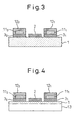
- Figure 3 shows a second embodiment which is a modified example of the fuel-cell device utilizing surface-migration on organic solid shown in Figure 1B.
- the basic structure of this modified example is the same as that of the fuel-cell device utilizing surface-migration on organic solid shown in Figure 1B, the only difference being that all the surfaces of the fuel supply layers 11 1 and 11 2 , except the surfaces contacting the anode layers 3 1 and 3 2 , are covered with the respective cover layers 12 1 and 12 2 .
- This structure prevents the fluid fuel from leaking or evaporating from the fuel supply layers, and enhances the fuel-rich condition of each anode layer while ensuring the oxygen-rich condition of the cathode layer, as the air can be clearly separated from the fluid fuel. It also becomes possible to forcefully blow air to the cathode layer so that the cathode layer can be effectively exposed to the air. When air is blown in this way, reaction products can also be removed forcefully, and the power generation efficiency improves.
- Figure 4 shows a third embodiment which concerns a specific example in which the fuel-cell device utilizing surface-migration on organic solid shown in any one of Figures 1 to 3 is mounted on a second substrate 13.
- Any fuel-cell device utilizing surface-migration on organic solid shown in Figures 1 to 3 can be mounted on the second substrate 13, though Figure 4 specifically shows the case of the fuel-cell device utilizing surface-migration on organic solid of Figure 3.
- the second substrate 13 may be a reinforcing substrate for reinforcing the structure of the fuel-cell device itself, or may be a heat-exchange substrate for dissipating the heat generated during power generation.
- a printed wiring board may be used as the second substrate, or alternatively, the fuel-cell device may be formed directly on a semiconductor substrate, for example, on an insulating film of a semiconductor chip.
- a fourth embodiment shown in Figures 5A and 5B concerns a specific example in which the fuel supply layers are arranged differently than those described above.
- Figure 5A shows a cross-sectional view taken along line A-A in Figure 5B.
- strip-shaped cathode layers and strip-shaped anode layers are arranged parallel to each other on one surface of the solid organic substrate 1, and the surface regions are formed on the substrate between the respective layers, thus forming fuel cells; in this respect, there is no difference from the fuel-cell devices utilizing surface-migration on organic solid described above, but the difference is that, rather than arranging the cathode layers and the anode layers one alternating with the other, pairs of anode layers, 3 1 and 3 2 , and 3 3 and 3 4 , are arranged so as to be sandwiched alternately between the respective cathode layers 2 1 , 2 2 , and 2 3 . Then, the fuel supply layers 11 1 and 11 2 are each interposed between the corresponding pair of anode layers in contacting relationship with the side surfaces of the anode layers.
- This structure serves to reduce the number of fuel supply layers, while ensuring effective supply of the fluid fuel. Further, as the fuel supply layers are arranged on the same plane as the anode layers in contacting relationship with their sides, the thickness of the fuel-cell device can be further reduced, making it easier to stack a plurality of fuel-cell devices.
- FIG. 6 shows a modified example of the fourth embodiment shown in Figures 5A and 5B.
- a cover layer is provided on each of the fuel supply layers of the fuel-cell device utilizing surface-migration on organic solid.
- the air supply and the fuel supply can be separated from each other as long as the cover layer is formed to cover at least the fuel supply layer; in Figure 6, however, to ensure an even more reliable separation, the cover layers 12 1 and 12 2 are formed to also cover the anode layers 3 1 and 3 2 , and 3 3 and 3 4 , respectively.
- the fuel-cell device utilizing surface-migration on organic solid of the fourth embodiment shown in Figures 5 and 6 can also be formed on a second substrate.
- the solid organic substrate used in the fuel-cell devices utilizing surface-migration on organic solid of the embodiments described above can be formed, for example, from a polyethylene terephthalate resin, a polyester resin, an epoxy resin, a polyimide resin, polyvinylidene chloride, polyethylene, or the like. Using such resins, the solid organic substrate may be formed in the form of a block or in the form of a sheet. Further, the substrate may be formed in a laminated structure.
- the anode layers formed on one surface of the solid organic substrate are constructed using rhenium (Re), tungsten (W), nickel (Ni), molybdenum (Mo), copper (Cu), or the like. These metals are used in the powdered or powder particle state to directly form the layers, or sintered into a porous structure. Alternatively, metal plates made of an iron-nickel-chromium alloy may be used directly as the anode layers.
- the cathode layers arranged in parallel to the anode layers on the same surface of the solid organic substrate can be constructed using, for example, samarium strontium cobaltite or other known material such as lanthanum manganite doped with an element, for example, strontium (Sr), from group III of the periodic table (for example, lanthanum strontium manganite) or a lanthanum gallium oxide or cobalt oxide compound doped with such an element (for example, lanthanum strontium cobaltite).
- the cathode layers and anode layers of the fuel-cells utilizing surface-migration on organic solid of the above embodiments are both formed from porous materials, it is preferable to form the surface of the solid organic substrate as smooth as possible, because the surface regions over which the oxygen ions migrate need to be formed on the surface. Accordingly, it will be advantageous to form the solid organic substrate as a very compact structure.
- the operating temperature for power generation can be lowered; as a result, unlike the solid electrolyte fuel-cell devices of the prior art, there is no concern of possible cracking of the substrate due to thermal history.
- the fuel-cells utilizing surface-migration on organic solid according to the above embodiments are fabricated, for example, in the following manner.
- Strip-shaped or bar-shaped cathode layers preformed by calcining or other means and strip-shaped or bar-shaped anode layers likewise preformed are placed in parallel to each other, one spaced apart from another by a prescribed distance, on one surface of a flat plate-like organic substrate, and fuel supply layers are placed in contacting relationship with the anode layers.
- a fuel cell is formed between each cathode layer and its adjacent anode layer, and an electromotive force is induced between the lead wires respectively connected to the cathode layer and the anode layer.
- each strip of metal powder is formed on the substrate surface between the respective cathode layers with a prescribed spacing provided relative to each cathode layer.
- the metal powder may be prepared, for example, in the form of a paste, and the paste may be applied in a strip-like pattern and then dried to form the strip-shaped anode layers.
- metal layers preformed in a porous structure, or metal plates themselves, may be placed as the anode layers.
- the fuel supply layers for example, unwoven fabrics, having the same width as the anode layers, in the case of the fuel-cell device utilizing surface-migration on organic solid shown in Figures 1A and 1B, are pressed thereon, to complete the fabrication of the solid organic surface-utilizing fuel cells.
- a metal mesh that functions as an extraction electrode as well as a reinforcing member may be embedded in or fixed to the upper surface of each cathode layer.
- the substrate is formed from an organic material and is therefore flexible, it is important to take into account the possible cracking of the hard cathode layers formed by sintering or the like.
- the embedding method after embedding the metal mesh in the paste or green sheet forming the cathode layer, the resulting structure is calcined.
- the metal mesh is not completely embedded in the cathode layer material but may be fixed on a surface of it, followed by sintering.
- a material that has excellent heat resistance, and that well matches the thermal expansion coefficient of the cathode layer which the metal mesh is to be embedded in or fixed to is suitable.
- Specific examples include platinum metal and a platinum-containing metal alloy formed in the shape of a mesh.
- stainless steel of SUS 300 series (304, 316, etc.) or SUS 400 series (430, etc.) may be used; these materials are advantageous in terms of cost.
- metal wires may be embedded in or fixed to the cathode layer.
- the metal wires are formed using the same metal material as that used for the metal mesh, and the number of wires and the configuration of the wire arrangement are not limited to any particular number or configuration.
- the metal mesh or metal wires embedded in or fixed to the cathode layer serve to reinforce the structure so that the cathode layer, if cracked, will not disintegrate into pieces; furthermore, the metal mesh or the metal wires act to electrically connect the cracked portions, and function as a current collecting electrode, so that the power generation performance of the fuel cell does not degrade and the fuel cell can continue to generate electricity.
- the anode layers are formed from metal powder particles
- the anode layers need not necessarily be provided with a metal mesh or metal wires, since the anode layers themselves flexibly deform because of the powder particles, accommodating the flexible structure of the solid organic substrate. Accordingly, when each anode layer is formed from powder particles, the effective area of the anode layer is maintained, and thus, the durability of the fuel-cell device utilizing surface-migration on organic solid can be enhanced.
- Figure 7A shows a configuration in which a plurality of fuel-cell devices utilizing surface-migration on organic solid, each identical to that shown in Figure 2, are fabricated on one solid organic substrate.
- a plurality of groups, each comprising a plurality of cathode layers, are each connected at one end to a common cathode 2
- a plurality of groups, each comprising a plurality of anode layers are each connected at one end to a common anode 3; in this manner, all the fuel cells formed on the substrate are connected in parallel.
- a lead wire L1 is brought out of the common cathode 2, while a lead wire L2 is brought out of the common anode 3, and the power generation capacity to be output between the lead wires L1 and L2 is thus increased.
- Figure 7A the common cathode 2 and the common anode 3 are used to connect the fuel cells in parallel between the plurality of groups; on the other hand, Figure 7B shows an example in which all the fuel cells are connected in parallel by using connecting wires W1 and W2 instead of using the common cathode 2 and the common anode 3.
- two fuel-cell device utilizing surface-migration on organic solid groups are fabricated on one solid organic substrate; here, the common cathode 2 of the first group is overlaid on the common anode 3 of the second group to form a common anode 32, and the lead wire L2 is brought out of the common anode 31 of the first group, while the lead wire L1 is brought out of the common cathode 22 of the second group.
- the electromotive force to be induced between the lead wires L1 and L2 can be increased, while retaining the power generation capacity of the fuel-cell device utilizing surface-migration on organic solid shown in Figure 7A. If it is desired to further increase the electromotive force, this can be accomplished by sequentially connecting a plurality of fuel-cell device utilizing surface-migration on organic solid groups by overlaying the common cathode of one group on the common anode of the next group as shown in Figure 8.
- a polyester film was used as the solid organic substrate.
- a strip of sintered SSC-SDC containing 50% by weight of Sm 0.5 Sr 0.5 CoO 3 was placed as a cathode layer on one surface of the film substrate.
- a strip of rhenium metal powder was applied on the same surface to form an anode layer by providing a spacing of about 0.1 mm or less relative to the cathode layer. Then, ethanol-impregnated gauze was placed in contact with the anode layer.
- test leads were connected to the cathode layer and the anode layer, at room temperature, an open circuit voltage of about 0.8 V and a short-circuit current of about 120 ⁇ A were obtained.
- a polyester film was used as the solid organic substrate.
- a strip of sintered SSC-SDC as a cathode layer and a strip-shaped tungsten plate as an anode layer were placed, one spaced apart from the other by about 0.1 mm or less, on one surface of the film substrate. Then, gauze dampened with ethanol was placed near the anode layer.
- test leads were connected to the cathode layer and the anode layer, at room temperature, an open circuit voltage of about 0.3 V was obtained, and the short-circuit current at this time was about 6 ⁇ A.
- a strip of sintered SSC-SDC as a cathode layer was placed on a polyimide resin layer formed on a silicon wafer, and a strip of rhenium metal powder was placed to form an anode layer by providing a spacing of about 0.1 mm or less relative to the cathode layer. Then, gauze dampened with ethanol was placed near the anode layer to impregnate the anode layer with the ethanol.
- test leads were connected to the cathode layer and the anode layer, at room temperature, an open circuit voltage of about 0.3 V was obtained, and the short-circuit current at this time was about 90 ⁇ A.
- the cathode layers and the anode layers are arranged in parallel and in close proximity to each other on a solid organic substrate, and the cathode layers are exposed to the air in the atmosphere, while the anode layers are arranged each contacting a fuel supply layer so that a fluid fuel is supplied directly to the anode layers; as a result, an oxygen-rich condition can be easily maintained at the cathode layers, and a fuel-rich condition at the anode layers, by employing a simple structure that does not require a special hermetically sealed construction, thus achieving reductions in the size and cost of the fuel-cell device utilizing surface-migration on organic solid.
- a fuel-cell device utilizing surface-migration on organic solid can be achieved that can reduce the operating temperature for power generation. Further, as the reduced operating temperature makes it easier to use an organic material for the substrate, a fuel-cell device can be achieved that is highly flexible, inexpensive, and simple in structure, and the usability of the fuel-cell device can thus be enhanced.
Landscapes
- Life Sciences & Earth Sciences (AREA)
- Engineering & Computer Science (AREA)
- Manufacturing & Machinery (AREA)
- Sustainable Development (AREA)
- Sustainable Energy (AREA)
- Chemical & Material Sciences (AREA)
- Chemical Kinetics & Catalysis (AREA)
- Electrochemistry (AREA)
- General Chemical & Material Sciences (AREA)
- Fuel Cell (AREA)
- Inert Electrodes (AREA)
Applications Claiming Priority (2)
| Application Number | Priority Date | Filing Date | Title |
|---|---|---|---|
| JP2003209384 | 2003-08-28 | ||
| JP2003209384A JP2005071659A (ja) | 2003-08-28 | 2003-08-28 | 固体有機物表面利用燃料電池 |
Publications (2)
| Publication Number | Publication Date |
|---|---|
| EP1511114A2 true EP1511114A2 (de) | 2005-03-02 |
| EP1511114A3 EP1511114A3 (de) | 2006-04-19 |
Family
ID=34100735
Family Applications (1)
| Application Number | Title | Priority Date | Filing Date |
|---|---|---|---|
| EP04255173A Withdrawn EP1511114A3 (de) | 2003-08-28 | 2004-08-26 | Brennstoffzellenanlage |
Country Status (3)
| Country | Link |
|---|---|
| US (1) | US20050048355A1 (de) |
| EP (1) | EP1511114A3 (de) |
| JP (1) | JP2005071659A (de) |
Cited By (1)
| Publication number | Priority date | Publication date | Assignee | Title |
|---|---|---|---|---|
| WO2006058357A3 (de) * | 2004-12-03 | 2007-01-18 | Fotec Forschungs Und Technolog | Mikroreaktor, insbesondere brennstoffzelle und verfahren zur herstellung |
Families Citing this family (2)
| Publication number | Priority date | Publication date | Assignee | Title |
|---|---|---|---|---|
| JP6225450B2 (ja) * | 2013-03-28 | 2017-11-08 | 凸版印刷株式会社 | 膜電極接合体、および、固体高分子形燃料電池 |
| RU196629U1 (ru) * | 2019-12-13 | 2020-03-10 | Публичное акционерное общество "КАМАЗ" | Мембранно-электродный блок твердооксидного топливного элемента с контактными слоями |
Family Cites Families (7)
| Publication number | Priority date | Publication date | Assignee | Title |
|---|---|---|---|---|
| US4248941A (en) * | 1979-12-26 | 1981-02-03 | United Tecnologies Corporation | Solid electrolyte electrochemical cell |
| US6183898B1 (en) * | 1995-11-28 | 2001-02-06 | Hoescht Research & Technology Deutschland Gmbh & Co. Kg | Gas diffusion electrode for polymer electrolyte membrane fuel cells |
| EP1190460A4 (de) * | 1999-05-06 | 2003-03-12 | Sandia Corp | Brennstoffzelle und membran |
| US6890677B2 (en) * | 1999-05-06 | 2005-05-10 | Sandia Corporation | Fuel cell and membrane |
| US6541149B1 (en) * | 2000-02-29 | 2003-04-01 | Lucent Technologies Inc. | Article comprising micro fuel cell |
| JP3860733B2 (ja) * | 2001-09-17 | 2006-12-20 | 新光電気工業株式会社 | 燃料電池 |
| US6649211B2 (en) * | 2002-02-28 | 2003-11-18 | The United States Of America As Represented By The Secretary Of The Navy | Selective deposition of hydrous ruthenium oxide thin films |
-
2003
- 2003-08-28 JP JP2003209384A patent/JP2005071659A/ja active Pending
-
2004
- 2004-08-26 EP EP04255173A patent/EP1511114A3/de not_active Withdrawn
- 2004-08-30 US US10/928,130 patent/US20050048355A1/en not_active Abandoned
Cited By (1)
| Publication number | Priority date | Publication date | Assignee | Title |
|---|---|---|---|---|
| WO2006058357A3 (de) * | 2004-12-03 | 2007-01-18 | Fotec Forschungs Und Technolog | Mikroreaktor, insbesondere brennstoffzelle und verfahren zur herstellung |
Also Published As
| Publication number | Publication date |
|---|---|
| US20050048355A1 (en) | 2005-03-03 |
| EP1511114A3 (de) | 2006-04-19 |
| JP2005071659A (ja) | 2005-03-17 |
Similar Documents
| Publication | Publication Date | Title |
|---|---|---|
| US5312700A (en) | Solid oxide fuel cell and method for producing the same | |
| US20040076868A1 (en) | Fuel cell and method for forming | |
| US8182658B2 (en) | Electrochemical device and exhaust gas purification apparatus | |
| US7163759B2 (en) | Solid oxide fuel cell stack assembly having tapered diffusion layers | |
| JP5254588B2 (ja) | 固体酸化物形燃料電池モジュール | |
| US7449261B2 (en) | Holding member for holding an electrochemical cell, a holding substrate for the same, an electrochemical system and a connecting member for electrochemical cells | |
| EP1508932B1 (de) | Festelektrolytbrennstoffzellenvorrichtung | |
| US5326650A (en) | Solid oxide fuel electrodes and process for producing | |
| US7470480B2 (en) | Solid electrolyte fuel-cell device | |
| JP4249960B2 (ja) | 燃料電池セル | |
| US20050048352A1 (en) | Fuel-cell device utilizing surface-migration on solid oxide | |
| US20050048355A1 (en) | Fuel-cell device utilizing surface-migration on organic solid | |
| JP2004172062A (ja) | 燃料電池及び多層燃料電池用セル | |
| US20070141435A1 (en) | Fuel cell with a brazed interconnect and method of assembling the same | |
| JP5114999B2 (ja) | 固体酸化物形燃料電池及びそのスタック構造 | |
| JPH0722058A (ja) | 平板状固体電解質燃料電池 | |
| US20080193816A1 (en) | Fuel cell with substrate-patterned lower electrode | |
| JP5168865B2 (ja) | 単室型固体酸化物形燃料電池のスタック構造 | |
| EP4503209A2 (de) | Elektrochemischer festoxidzellenstapel | |
| JP2008021596A (ja) | 固体電解質形燃料電池モジュール | |
| US10680270B2 (en) | Fuel cell ink trace interconnect | |
| US20190157705A1 (en) | Multiple fuel cell secondary interconnect bonding pads and wires | |
| JPH04282566A (ja) | 固体電解質型燃料電池用インターコネクター及びこれを有する固体電解質型燃料電池 | |
| JP2013093181A (ja) | 燃料電池の構造体 | |
| KR20190057015A (ko) | 연료 전지 시스템의 이차 상호접속부 |
Legal Events
| Date | Code | Title | Description |
|---|---|---|---|
| PUAI | Public reference made under article 153(3) epc to a published international application that has entered the european phase |
Free format text: ORIGINAL CODE: 0009012 |
|
| AK | Designated contracting states |
Kind code of ref document: A2 Designated state(s): AT BE BG CH CY CZ DE DK EE ES FI FR GB GR HU IE IT LI LU MC NL PL PT RO SE SI SK TR |
|
| AX | Request for extension of the european patent |
Extension state: AL HR LT LV MK |
|
| RIN1 | Information on inventor provided before grant (corrected) |
Inventor name: SUGANUMA, S,SHINKO ELECTRIC INDUSTRIES CO., LTD. Inventor name: WATANABE, M.,SHINKO ELECTRIC INDUSTRIES CO., LTD. Inventor name: HORIUCHI, M.,SHINKO ELECTRIC INDUSTRIES CO., LTD. |
|
| PUAL | Search report despatched |
Free format text: ORIGINAL CODE: 0009013 |
|
| AK | Designated contracting states |
Kind code of ref document: A3 Designated state(s): AT BE BG CH CY CZ DE DK EE ES FI FR GB GR HU IE IT LI LU MC NL PL PT RO SE SI SK TR |
|
| AX | Request for extension of the european patent |
Extension state: AL HR LT LV MK |
|
| RIC1 | Information provided on ipc code assigned before grant |
Ipc: H01M 8/24 20060101ALI20050107BHEP Ipc: H01M 8/10 20060101AFI20060228BHEP |
|
| AKX | Designation fees paid | ||
| REG | Reference to a national code |
Ref country code: DE Ref legal event code: 8566 |
|
| STAA | Information on the status of an ep patent application or granted ep patent |
Free format text: STATUS: THE APPLICATION IS DEEMED TO BE WITHDRAWN |
|
| 18D | Application deemed to be withdrawn |
Effective date: 20061020 |