EP1511098B1 - Brennstoffzellenstapel und Verfahren zu seiner Herstellung - Google Patents
Brennstoffzellenstapel und Verfahren zu seiner Herstellung Download PDFInfo
- Publication number
- EP1511098B1 EP1511098B1 EP04020302A EP04020302A EP1511098B1 EP 1511098 B1 EP1511098 B1 EP 1511098B1 EP 04020302 A EP04020302 A EP 04020302A EP 04020302 A EP04020302 A EP 04020302A EP 1511098 B1 EP1511098 B1 EP 1511098B1
- Authority
- EP
- European Patent Office
- Prior art keywords
- gas diffusion
- diffusion layer
- load
- fuel cell
- gas
- Prior art date
- Legal status (The legal status is an assumption and is not a legal conclusion. Google has not performed a legal analysis and makes no representation as to the accuracy of the status listed.)
- Expired - Lifetime
Links
Images


Classifications
-
- H—ELECTRICITY
- H01—ELECTRIC ELEMENTS
- H01M—PROCESSES OR MEANS, e.g. BATTERIES, FOR THE DIRECT CONVERSION OF CHEMICAL ENERGY INTO ELECTRICAL ENERGY
- H01M4/00—Electrodes
- H01M4/86—Inert electrodes with catalytic activity, e.g. for fuel cells
- H01M4/88—Processes of manufacture
- H01M4/8817—Treatment of supports before application of the catalytic active composition
- H01M4/8821—Wet proofing
-
- H—ELECTRICITY
- H01—ELECTRIC ELEMENTS
- H01M—PROCESSES OR MEANS, e.g. BATTERIES, FOR THE DIRECT CONVERSION OF CHEMICAL ENERGY INTO ELECTRICAL ENERGY
- H01M4/00—Electrodes
- H01M4/86—Inert electrodes with catalytic activity, e.g. for fuel cells
- H01M4/88—Processes of manufacture
- H01M4/8803—Supports for the deposition of the catalytic active composition
- H01M4/8807—Gas diffusion layers
-
- H—ELECTRICITY
- H01—ELECTRIC ELEMENTS
- H01M—PROCESSES OR MEANS, e.g. BATTERIES, FOR THE DIRECT CONVERSION OF CHEMICAL ENERGY INTO ELECTRICAL ENERGY
- H01M4/00—Electrodes
- H01M4/86—Inert electrodes with catalytic activity, e.g. for fuel cells
- H01M4/88—Processes of manufacture
- H01M4/8817—Treatment of supports before application of the catalytic active composition
-
- H—ELECTRICITY
- H01—ELECTRIC ELEMENTS
- H01M—PROCESSES OR MEANS, e.g. BATTERIES, FOR THE DIRECT CONVERSION OF CHEMICAL ENERGY INTO ELECTRICAL ENERGY
- H01M8/00—Fuel cells; Manufacture thereof
- H01M8/02—Details
- H01M8/0202—Collectors; Separators, e.g. bipolar separators; Interconnectors
- H01M8/023—Porous and characterised by the material
- H01M8/0234—Carbonaceous material
-
- H—ELECTRICITY
- H01—ELECTRIC ELEMENTS
- H01M—PROCESSES OR MEANS, e.g. BATTERIES, FOR THE DIRECT CONVERSION OF CHEMICAL ENERGY INTO ELECTRICAL ENERGY
- H01M8/00—Fuel cells; Manufacture thereof
- H01M8/02—Details
- H01M8/0202—Collectors; Separators, e.g. bipolar separators; Interconnectors
- H01M8/023—Porous and characterised by the material
- H01M8/0241—Composites
- H01M8/0245—Composites in the form of layered or coated products
-
- H—ELECTRICITY
- H01—ELECTRIC ELEMENTS
- H01M—PROCESSES OR MEANS, e.g. BATTERIES, FOR THE DIRECT CONVERSION OF CHEMICAL ENERGY INTO ELECTRICAL ENERGY
- H01M8/00—Fuel cells; Manufacture thereof
- H01M8/24—Grouping of fuel cells, e.g. stacking of fuel cells
- H01M8/2465—Details of groupings of fuel cells
- H01M8/247—Arrangements for tightening a stack, for accommodation of a stack in a tank or for assembling different tanks
-
- Y—GENERAL TAGGING OF NEW TECHNOLOGICAL DEVELOPMENTS; GENERAL TAGGING OF CROSS-SECTIONAL TECHNOLOGIES SPANNING OVER SEVERAL SECTIONS OF THE IPC; TECHNICAL SUBJECTS COVERED BY FORMER USPC CROSS-REFERENCE ART COLLECTIONS [XRACs] AND DIGESTS
- Y02—TECHNOLOGIES OR APPLICATIONS FOR MITIGATION OR ADAPTATION AGAINST CLIMATE CHANGE
- Y02E—REDUCTION OF GREENHOUSE GAS [GHG] EMISSIONS, RELATED TO ENERGY GENERATION, TRANSMISSION OR DISTRIBUTION
- Y02E60/00—Enabling technologies; Technologies with a potential or indirect contribution to GHG emissions mitigation
- Y02E60/30—Hydrogen technology
- Y02E60/50—Fuel cells
-
- Y—GENERAL TAGGING OF NEW TECHNOLOGICAL DEVELOPMENTS; GENERAL TAGGING OF CROSS-SECTIONAL TECHNOLOGIES SPANNING OVER SEVERAL SECTIONS OF THE IPC; TECHNICAL SUBJECTS COVERED BY FORMER USPC CROSS-REFERENCE ART COLLECTIONS [XRACs] AND DIGESTS
- Y02—TECHNOLOGIES OR APPLICATIONS FOR MITIGATION OR ADAPTATION AGAINST CLIMATE CHANGE
- Y02P—CLIMATE CHANGE MITIGATION TECHNOLOGIES IN THE PRODUCTION OR PROCESSING OF GOODS
- Y02P70/00—Climate change mitigation technologies in the production process for final industrial or consumer products
- Y02P70/50—Manufacturing or production processes characterised by the final manufactured product
-
- Y—GENERAL TAGGING OF NEW TECHNOLOGICAL DEVELOPMENTS; GENERAL TAGGING OF CROSS-SECTIONAL TECHNOLOGIES SPANNING OVER SEVERAL SECTIONS OF THE IPC; TECHNICAL SUBJECTS COVERED BY FORMER USPC CROSS-REFERENCE ART COLLECTIONS [XRACs] AND DIGESTS
- Y10—TECHNICAL SUBJECTS COVERED BY FORMER USPC
- Y10T—TECHNICAL SUBJECTS COVERED BY FORMER US CLASSIFICATION
- Y10T29/00—Metal working
- Y10T29/49—Method of mechanical manufacture
- Y10T29/49002—Electrical device making
- Y10T29/49108—Electric battery cell making
- Y10T29/49115—Electric battery cell making including coating or impregnating
Definitions
- This invention relates to a fuel cell stack which uses a polymer electrolyte membrane.
- a fuel cell converts chemical energy contained in fuel directly into electric energy by causing a fuel gas such as hydrogen and an oxidizer gas such as air to react electrochemically.
- a fuel gas such as hydrogen
- an oxidizer gas such as air
- One type of fuel cell is a polymer electrolyte fuel cell (PEFC), which uses a polymer electrolyte as an electrolyte.
- PEFC polymer electrolyte fuel cell
- reaction gas fuel gas and oxidizer gas
- a reaction surface i.e. the surface of the electrolyte membrane
- the gas diffusion layer is disposed in contact with a separator, in which a passage allowing gas flow is formed. More specifically, the gas diffusion layer contacts a rib defining the passage in the separator.
- a fuel cell stack is typically fastened together in the lamination direction by bolts or bands, and hence the gas diffusion layer receives a load (or pressure) from the rib of the separator.
- the region of the gas diffusion layer which contacts the rib and is subjected to a load from the rib is known as a compressed region (or rib-contacting part).
- a non-compressed region (or gas diffusion portion) of the gas diffusion layer which faces the passage in the separator does not receive the stack-fastening load (i.e. pressure from the rib) that is received by the compressed region.
- the non-compressed region which faces the passage swells toward the passage side.
- the cross-sectional area of the passage decreases, inhibiting the gas flow through the passage, and swelling of the gas diffusion layer toward the gas passage must therefore be suppressed.
- gas diffusivity differs within the gas diffusion layer according to the state of compression. Since the state of compression differs between the non-compressed region and compressed region, a difference arises in the gas diffusivity of the two regions. It is therefore desirable that the gas diffusivity be as uniform as possible in the non-compressed region and the compressed region.
- Tokkai 2002-343379 published by the Japan Patent Office in 2002, discloses a technique of regulating the gas diffusivity within the gas diffusion layer. By pressing the gas diffusion layer in the direction of thickness during manufacture, the gas diffusivity within the gas diffusion layer is regulated to a design value.
- WO 03034519 describes a fuel-cell carbon fiber woven fabric and the use thereof for an electrode diffusion layer on an electrode element of a fuel cell, wherein the fabric has a defined average size of warps and wefts and a certain density.
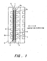
- FIG. 1 is a schematic sectional view showing the constitution of a fuel cell stack to which this invention is applied.
- FIG. 2 is a graph showing the relationship between a load (pressure) applied to a gas diffusion layer and the thickness of the gas diffusion layer.
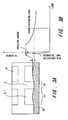
- FIG. 3A is an enlarged sectional view of the gas diffusion layer and a gas passage.
- FIG. 3B is a graph showing the relationship between the thickness of the gas diffusion layer and a load (pressure) applied in a stack lamination direction.
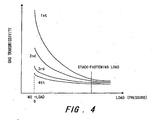
- FIG. 4 is a graph showing the relationship between the load (pressure) applied to the gas diffusion layer and the gas transmissivity of the gas diffusion layer.
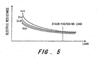
- FIG. 5 is a graph showing the relationship between the load (pressure) applied to the gas diffusion layer and the electric resistance of the gas diffusion layer.
- FIG. 6 is a graph showing the relationship between the load (pressure) applied to the gas diffusion layer and the thickness of the gas diffusion layer.
- FIG. 7 is a diagram illustrating a manufacturing method of the gas diffusion layer.
- FIG. 8 is a diagram illustrating another manufacturing method of the gas diffusion layer.
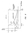
- FIG. 9 is a graph showing the relationship between the load (pressure) applied to a surface-processed gas diffusion layer and the thickness of the gas diffusion layer.
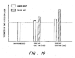
- FIG. 10 is a diagram, illustrating the effects of this invention.
- FIG. 1 is a sectional view showing the constitution of a polymer electrolyte fuel cell stack of this invention.
- the fuel cell stack is constituted by laminating a plurality of single cells.
- the fuel cell stack is fastened in the lamination direction by bolts or bands, for example.
- a single cell is constituted by a membrane electrode assembly (MEA) and a separator 3.
- the MEA comprises a polymer electrolyte membrane 1, and two electrodes (a fuel electrode and an oxidizer electrode) 2 disposed on either side of the electrolyte membrane 1.
- the electrodes 2 are constituted by a catalyst electrode layer 2a on which a catalyst is carried, and a gas diffusion layer 2b.
- the separator 3 comprises a gas passage, through which fuel gas and oxidizer gas are supplied to the electrodes 2 to generate power, and a cooling water passage, through which a refrigerant for cooling the stack flows. Two of the separators 3 sandwich the membrane electrode assembly (MEA). More precisely, the gas passage 6 is defined by the electrode 2 and the body of the separator 3.
- Sealing members 5 are provided between the separator 3 and electrolyte membrane 1 so as to face the electrodes 2.
- the sealing members 5 are positioned on the outer edge parts of the separator 3.
- the sealing members 5 prevent fuel gas containing hydrogen, oxidizer gas containing oxygen, and refrigerant (e.g. cooling water) from leaking outside.
- the electrolyte membrane 1 is formed from a solid polymer material such as a fluororesin, and has a proton conducting property.
- the two catalyst electrode layers 2a disposed on each surface of the electrolyte membrane 1 are formed from carbon black comprising a catalyst that is constituted by platinum and/ or another metal.
- the gas diffusion layer 2b is formed from a porous material having gas transmissivity (i.e. gas diffusivity).
- the material of the gas diffusion layer 2b is either carbon cloth or carbon paper. Commercially available carbon cloth or carbon paper may be used.
- the separator 3 is formed from a molded carbon material having gas impermeability. A large number of grooves corresponding to fuel gas and oxidizer gas passages 6, 7 are formed on one or both surfaces of the separator 3.
- a refrigerant passage 8 for removing the heat that is generated from the fuel cell itself is provided in the separator 3 on the oxidizer electrode side.
- the refrigerant passage 8 does not necessarily have to be disposed in each cell, but it is desirable that as many as possible be provided.
- Oxidizer gas and fuel gas are supplied to each fuel cell from their respective gas inlets, and after contributing to power generation, are exhausted from gas outlets.
- FIG. 2 shows change in the thickness of the gas diffusion layer 2b when a load (in other words, pressure) is applied repeatedly to the gas diffusion layer 2b in the lamination direction of the stack during manufacture.
- the load is applied up to a maximum value Lmax , and then released.
- Lmax is 3MPa.
- the thickness of the gas diffusion layer decreases in accordance with the load, and recovers to a certain extent when the load is removed.
- the thickness of the gas diffusion layer decreases by an amount of thickness change ( ⁇ T) corresponding to the plastic deformation which occurs during a single cycle of load application and removal.
- ⁇ T thickness change
- the amount of change (Dn) in the thickness of the gas diffusion layer 2b during load application decreases such that the gas diffusion layer 2b becomes durable in relation to loads.
- the amount of change in the thickness of the gas diffusion layer 2b (or swelling toward the gas passage side) caused by the application of a load is suppressed during fastening of the stack in particular.
- irregularities in the thickness of the gas diffusion layer 2b in each of the cells are suppressed even when pressure irregularities occur among the cells as a result of stack fastening.
- FIG. 3A shows a schematic cross section of the gas passages 6, 7 and gas diffusion layer 2b in the stack lamination direction.
- FIG. 3B shows change in the thickness of the gas diffusion layer 2b in relation to a load in the stack fastening direction, in other words, pressure on the gas diffusion layer from the separator.
- a gas diffusion part 2c (non-compressed region) of the gas diffusion layer 2b, which faces the gas passages 6, 7, receives less stack fastening pressure than a rib-contacting part 2d (compressed region) which contacts a rib 9.
- the thickness of the gas diffusion part 2c undergoes substantially no change when the load is applied, and as a result, the gas diffusion part 2c takes a form which swells toward the gas passage side.
- the rate of change in the thickness of the gas diffusion layer 2b upon the application of a load during stack fastening is suppressed to a low level by repeatedly applying a load to the gas diffusion layer 2b in the lamination direction during manufacture.
- swelling of the gas diffusion part 2c toward the gas passages 6, 7 is suppressed, enabling the sectional area of the gas passages 6, 7 to be largely ensured.
- the gas flow property can be ensured, and reductions in the generation efficiency of the fuel cell stack can be prevented.
- FIG. 4 shows the relationship between the load (surface pressure) on the gas diffusion layer 2b and the gas transmissivity or diffusivity.
- the gas transmissivity through the gas diffusion layer decreases gradually in accordance with the repeated application of the load.
- the gas transmissivity converges at a predetermined value, and the pattern of change in the gas transmissivity converges into a fixed pattern.
- the difference in gas transmissivity under a non-loaded condition and a loaded condition contracts gradually, and thus the difference in gas transmissivity between the gas diffusion part 2c and the rib-contacting part 2d is suppressed.
- gas transmissivity to the catalyst electrode layer 2a worsens slightly, but the concentration of the diffused gas becomes uniform over the reaction surface, which is perpendicular to the lamination direction.
- FIG. 5 shows the relationship between the load on the gas diffusion layer 2b and the electric resistance.
- the electric resistance of the gas diffusion layer 2b is measured using a four-terminal method by disposing electrodes on each side of the gas diffusion layer 2b. As the load increases, the electric resistance of the gas diffusion layer 2b decreases, and then converges at a fixed value. Similarly to the thickness of the gas diffusion layer in FIG. 2 and the gas transmissivity in FIG. 4 , the electric resistance converges at a fixed value when the load is applied repeatedly. By applying the load repeatedly in this manner, the electric resistance of the gas diffusion layer 2b can be reduced. Moreover, the rate of change in the electric resistance value is greatly reduced by load application, and hence resistance irregularities in the cell lamination direction, occurring in the gas diffusion layer 2b within the perpendicular surface to the lamination direction, are suppressed to a low level.
- the thickness of the gas diffusion layer 2b following the (n-1)th load application and removal cycle is expressed by T n-1
- the thickness of the gas diffusion layer 2b following the nth load application and removal cycle is expressed by T n .
- the rate of change is defined as ⁇ T n /T n-1 ⁇ 100(%).
- the thickness of the gas diffusion layer 2b converges at a fixed value as the load increases, and it is therefore preferable to compare the thickness during the non-loaded period before and after one load application in order to ascertain the change in thickness.
- the thickness may be measured in micrometers.
- a feature of the manufactured gas diffusion layer is that when a load (in particular, a load equal to or less than the maximum value Lmax ) is applied and removed in the lamination direction, the rate of change in the thickness of the gas diffusion layer during the non-loaded period before and after load application falls to or below a predetermined value.
- a load in particular, a load equal to or less than the maximum value Lmax
- a maximum pressure Pmax corresponding to the maximum load value Lmax is set to be greater than a pressure Pr which would presumably be produced in the rib-contacting part 2d when the stack is fastened.
- the stack fastening pressure Pr produced by stack fastening were applied to and removed from the manufactured gas diffusion layer, the rate of change in the thickness of the gas diffusion layer in a non-loaded state before and after application of the pressure would be no greater than the predetermined value.
- a rate of thickness change D n /T n-1 ⁇ 100(%) during load application may be used as a target for the change in thickness before and after load application, instead of ⁇ T n /T n-1 ⁇ 100(%).
- the load application and removal cycle may be repeated until the rate of thickness change D n /T n-1 during load application falls to or below the predetermined value.
- D n is the difference between the thickness (T n-1 ) at zero load and the thickness at the maximum load Lmax during the nth load application.
- the predetermined value for the rate of thickness change in the gas diffusion layer 2b constituted by a type of carbon paper may be comparatively large.
- the predetermined value for the rate of change ( ⁇ T n /T n-1 ⁇ 100%) is preferably less than 10%, and more preferably less than 5%. In an experiment, the rate of change ( ⁇ T n /T n-1 ⁇ 100%) fell below 5% after applying twice the load of 3MPa.
- the predetermined value for the rate of change is preferably set low.
- the predetermined value for the rate of change ( ⁇ T n /T n-1 ⁇ 100%) in the gas diffusion layer 2b constituted by a type of carbon cloth is preferably less than 5%, and more preferably less than 3%. In an experiment, the rate of change ( ⁇ T n /T n-1 ⁇ 100%) fell below 3% after applying 6-times the load of 3MPa.
- a typical method of assembling the membrane electrode assembly comprises a step of disposing the two catalyst electrode layers 2a on each side of the electrolyte membrane 1, a step of sandwiching the electrolyte membrane 1 and the two catalyst electrode layers 2a between the gas diffusion layers 2b from the two outside surfaces of the catalyst electrode layers 2a, and a step of hot-pressing all of the electrolyte membrane 1, catalyst electrode layers 2a, and gas diffusion layers 2b.
- a method of manufacturing the membrane electrode assembly of this invention comprises a step of applying a load repeatedly to the gas diffusion layer 2b alone before assembling the membrane electrode assembly.
- the gas diffusion layer 2b is cut corresponding to the size of the planned membrane electrode assembly, and then a load is applied to the gas diffusion layer 2b repeatedly before the membrane electrode assembly is assembled by the typical method described above.
- one method of applying a load to the gas diffusion layer 2b involves applying the load batchwise. This can be achieved by performing batch processing of the gas diffusion layer 2b intermittently, as shown in FIG. 7 . Having been subjected to repeated load application, the gas diffusion layer 2b is used to assemble the electrolyte membrane assembly.
- another method of applying a load to the gas diffusion layer 2b involves rolling the gas diffusion layer 2b. By providing a plurality of roller presses in a pressing process, the load can be applied to the gas diffusion layer 2b repeatedly.
- the maximum value Pmax of the pressure that is produced during application of a load on the gas diffusion layer 2b during manufacture is set to be greater than the stack-fastening pressure Pr to be applied to the rib-contacting part 2d of the gas diffusion layer 2b from the separator during stack fastening.
- the thickness of the gas diffusion layer 2b can be adjusted to the design thickness of the gas diffusion layer 2b during stack fastening.
- a large load is applied, and hence the load can be applied effectively with a comparatively small number of applications.
- the applied pressure is larger than the pressure required for fastening the stack, creeping of the gas diffusion layer 2b following stack fastening can be suppressed.
- the maximum pressure value Pmax is set to be lower than the stack-fastening pressure Pr .
- the number of repeated load applications increases, but the physical properties of the gas diffusion layer 2b (for example, the gas diffusion layer thickness, the gas transmissivity through the gas diffusion layer, and the electric resistance) can be controlled more precisely. Further, by applying a smaller load than the buckling load of the material (carbon cloth, carbon paper, and so on) constituting the gas diffusion layer 2b, damage to the gas diffusion layer 2b can be prevented.
- a cold press When a load is applied repeatedly to the gas diffusion layer 2b, a cold press may be used. Alternatively, the load may be applied after heating the gas diffusion layer 2b in advance. Particularly when a resin or the like which serves as a binding agent for binding the carbon fiber material forming the gas diffusion layer 2b is present within the gas diffusion layer, the bond between the binding agent and the carbon fibers can be reconstituted through heating.
- the temperature of the gas diffusion layer 2b is preferably no less than 80°C and no more than 350°C, and more preferably no less than 120°C and no more than 250°C.
- the gas diffusion layer 2b in which the amount of change caused by repeated load application has converged within the predetermined value, may be used only on the cathode side since the width of the passage facing the separator 3 is large on the cathode side.
- swelling of the gas diffusion layer 2b into the gas passage which is likely to occur on the cathode side where the passage is wide, can be prevented.
- Reductions in the sectional area of the passage caused by swelling of the gas diffusion layer 2b can also be prevented in the entire stack.
- the gas diffusion layer 2b having decreased gas transmissivity on at least the cathode side uniform gas diffusion can be obtained on the cathode side.
- the gas diffusivity of air, which serves as the cathode gas deteriorates in the interior of the gas diffusion layer 2b to a greater degree than the hydrogen which serves as the anode gas, but by reducing the gas transmissivity, the amount of gas circulating in the rib-contacting part 2d can be increased, enabling gas to be supplied to the electrolyte membrane 1 evenly.
- a second embodiment will be described.
- surface processing is implemented after forming the gas diffusion layer 2b characterized by the rate of thickness change under load being limited within the predetermined value.
- each step of a method for manufacturing a gas diffusion layer of the second embodiment will be described in sequence.
- a load is applied repeatedly to the gas diffusion layer 2b.
- the number of repetitions may be decreased depending on the load application time, enabling a reduction in cost.
- the optimum length of time for a single load application is selected in accordance with the tact time of the step.
- predetermined surface processing or surface coating is performed on the gas diffusion layer 2b.
- Water repellent processing is typically selected as the surface processing.
- hydrophilic processing may be selected, depending on the design concept of the stack or the operating conditions of the fuel cell.
- the electrolyte membrane 1 When hydrophilic processing is performed on the gas diffusion layer 2b, the electrolyte membrane 1 can be prevented from drying out. As a result, the moisture retention property of the electrolyte membrane 1 can be secured, and proton conductivity within the electrolyte membrane, which is necessary for power generation, can be sufficiently secured. This is effective on the upstream side of the gas passage, for example, where the electrolyte membrane 1 tends to dry out easily.
- Water repellent processing will be described below. First, the gas diffusion layer 2b is submerged in a water repellent processing liquid, and then the gas diffusion layer 2b is removed from the processing liquid and dried. As a result of this processing, the gas diffusion layer 2b becomes surface-processed.
- a water repellent processing liquid that is in general use may be used in the water repellent processing.
- the water repellent processing liquid include a fluororesin aqueous dispersion which includes fluororesin dispersed in an aqueous dispersion medium, a fluororesin alcohol dispersion which includes fluororesin dispersed in an alcohol dispersion medium, and so on.
- aqueous dispersions are often selected for their ease of handling during drying.
- fluororesins include polytetrafluoroethylene, tetrafluororethylene-ethylene copolymer, tetrafluoroethylene-hexafluoropropylene copolymer, and so on.
- the drying time is selected appropriately in consideration of the thickness of the gas diffusion layer 2b, the amount of surface treatment (or the amount of surface processing liquid) applied to the gas diffusion layer 2b, and the drying temperature. With regard to workability, the drying time is typically between fifteen and ninety minutes.
- FIG. 9 is a graph illustrating the amount of surface treatment applied to the surface-processed gas diffusion layer 2b and the thickness characteristic of the gas diffusion layer 2b in relation to surface pressure.
- the thickness of the gas diffusion layer decreases as the surface pressure increases, and then converges at a fixed value.
- the thickness of the gas diffusion layer 2b increases in accordance with the amount of applied surface treatment. Hence under the same stack fastening conditions, the gas diffusion layer 2b tends to be thicker when surface processing is implemented than when unprocessed.
- the results of the second embodiment will be described.
- a non-woven carbon material is used as the gas diffusion layer 2b.
- a gas diffusion layer that has not undergone surface processing is used as a reference.
- the samples are gas diffusion layers in which the amount (or weight) of applied surface treatment is approximately 10% and approximately 20% of the amount (weight) of the gas diffusion layer respectively.
- Teflon is the brand name of polytetrafluoroethylene
- the amount of surface treatment applied to the gas diffusion layer 2b was calculated from the weight of the gas diffusion layer 2b when removed from the Teflon solution.
- the thickness of the gas diffusion layer 2b of this invention can be reduced below that of the prior art. This is achieved in this invention by applying surface pressure to the gas diffusion layer repeatedly before surface processing to produce a certain degree of plastic deformation. The surface treatment is then filled into the exiting spaces. In this invention, surface pressure is applied to the gas diffusion layer repeatedly, and hence little space exists within the diffusion layer. Thus by reducing the required amount of surface treatment coating, the thickness of the gas diffusion layer is reduced when the stack is fastened. Reductions in the amount of applied surface treatment also lead to cost reductions.
- a problem that typically arises when surface processing is implemented on the gas diffusion layer 2b to improve the fuel cell performance is that the thickness of the cell increases. According to the manufacturing method of the gas diffusion layer 2b of this invention, however, the gaps between the cells can be reduced when the stack is fastened. As a result, the size of the fuel cell stack can be reduced and the output thereof can be increased, and thus a fuel cell which is suitable for use in a moving body (or vehicle) having limited disposal space is obtained.
- a fuel cell stack for use in a moving body requires several hundred cells, and hence even slight reductions in the thickness of each cell enables a great reduction in the overall size of the stack.
Landscapes
- Chemical & Material Sciences (AREA)
- Engineering & Computer Science (AREA)
- Manufacturing & Machinery (AREA)
- Chemical Kinetics & Catalysis (AREA)
- Electrochemistry (AREA)
- General Chemical & Material Sciences (AREA)
- Composite Materials (AREA)
- Life Sciences & Earth Sciences (AREA)
- Sustainable Development (AREA)
- Sustainable Energy (AREA)
- Fuel Cell (AREA)
- Inert Electrodes (AREA)
Claims (13)
- Herstellverfahren für einen Brennstoffzellenstapel, der durch Befestigen einer laminierten Zelle gebildet wird, wobei die Zelle Folgendes aufweist:- einen Membranelektrodenzusammenbau mit einer Polymer-Elektrolytmembran (1) und zwei Elektroden (2), wobei die beiden Elektroden, die durch eine katalytische Elektrodenschicht (2a) und eine poröse Gasdiffusionsschicht (2b) gebildet werden, die Polymer-Elektrolytmembran von beiden Seiten abstützen; und- einen Separator (3) mit einer Gasleitung (6, 7), die Brenngas oder gasförmiges Oxidationsmittel der Gasdiffusionsschicht zuführt,- wobei das Herstellverfahren für einen Brennstoffzellenstapel durch folgende Schritte gekennzeichnet ist:- Wiederholen eines Zyklus' des Aufbringens und Entfernens einer Last auf zumindest eine der Gasdiffusionsschichten in Laminierungsrichtung der Zelle vor dem Laminieren der Zelle, wobei der Zyklus wiederholt wird, bis ein Ausmaß der Änderung bei einer Dicke der Gasdiffusionsschicht (2b) in einem nicht belasteten Zustand, bevor und nachdem die Last aufgebracht ist, auf einen oder unter einen vorbestimmten Wert fällt, so dass der elektrische Widerstand der Gasdiffusionsschicht (2b) sich einem festgelegten Wert annähert; und- Laminieren der Zelle, und danach Befestigen der laminierten Zelle.
- Herstellverfahren für einen Brennstoffzellenstapel gemäß Anspruch 1, wobei ein Maximalwert (Pmax) eines Drucks, der in der Gasdiffusionsschicht (2b) erzeugt wird, wenn die Last aufgebracht wird, größer als ein Druck (Pr) ist, der auf die Gasdiffusionsschicht vom Separator aufgebracht wird, wenn der Brennstoffzellenstapel befestigt wird.
- Herstellverfahren für einen Brennstoffzellenstapel gemäß Anspruch 1 oder 2, wobei, wenn der Druck (Pr), der auf die Gasdiffusionsschicht vom Separator aufgebracht wird, während des Befestigens des Stapels näher an einem Druck ist, der bewirkt, dass die Gasdiffusionsschicht nachgibt, der Maximalwert (Pmax) des Drucks, der in der Gasdiffusionsschicht erzeugt wird, wenn die Last aufgebracht ist, kleiner eingestellt wird als der Druck (Pr), der während des Befestigens des Stapels aufgebracht wird.
- Herstellverfahren für einen Brennstoffzellenstapel gemäß Anspruch 1, wobei die Gasdiffusionsschicht (2b) durch ein Karbontuch gebildet wird, und- der Maximalwert (Pmax) des Drucks, der auf die Gasdiffusionsschicht während der Aufbringung der Last aufgebracht wird, kleiner als ein Druck ist, der bewirkt, dass das Karbontuch nachgibt.
- Herstellverfahren für einen Brennstoffzellenstapel gemäß Anspruch 1, wobei die Gasdiffusionsschicht (2b) durch Karbonpapier gebildet wird, und- der Maximalwert (Pmax) des Drucks, der auf die Gasdiffusionsschicht während der Aufbringung der Last aufgebracht wird, kleiner als ein Druck ist, der bewirkt, dass das Karbonpapier nachgibt.
- Herstellverfahren für einen Brennstoffzellenstapel gemäß einem der Ansprüche 1 bis 5, wobei die Last auf die Gasdiffusionsschicht (2b) bei einer vorbestimmten Temperatur, die größer als die Raumtemperatur ist, aufgebracht wird.
- Herstellverfahren für einen Brennstoffzellenstapel gemäß einem der Ansprüche 1 bis 6, wobei das Ausmaß der Änderung bei der Dicke durch ein Änderungsverhältnis (Tn-1 - Tn) / Tn-1 × 100 (%) definiert wird, wobei Tn-1 und Tn die Dicke der Gasdiffusionsschicht in einem nicht belasteten Zustand sind, die jeweils dem Ende eines (n-1)-ten-Zyklus' und eines n-ten-Zyklus' folgen.
- Brennstoffzellenstapel, der durch Befestigen einer laminierten Zelle gebildet ist, wobei die Zelle Folgendes aufweist:- einen Membranelektrodenzusammenbau mit einem Separator (3), der eine Gasleitung (6, 7), eine Polymer-Elektrolytmembran (1) und zwei Elektroden (2) aufweist, wobei jede Elektrode eine katalytische Elektrodenschicht (2a) und eine poröse Gasdiffusionsschicht (2b) aufweist und die die Polymer-Elektrolytmembran von beiden Seiten abstützen;- dadurch gekennzeichnet, dass der Brennstoffzellenstapel gemäß Anspruch 1 hergestellt ist.
- Brennstoffzellenstapel gemäß Anspruch 8, wobei ein Druck, der während der Aufbringung der Last erzeugt wird, im Wesentlichen gleich einem Druck ist, der auf die Gasdiffusionsschicht von zumindest einer Elektrode vom Separator aufgebracht wird, wenn der Stapel befestigt wird.
- Brennstoffzellenstapel gemäß Anspruch 8 oder 9, wobei die zumindest eine Elektrode eine Elektrode an einer Oxidationselektrodenseite ist.
- Brennstoffzellenstapel gemäß einem der Ansprüche 8 bis 10, wobei die Oberflächenbearbeitung auf zumindest einer Gasdiffusionsschicht ausgeführt wird.
- Brennstoffzellenstapel gemäß Anspruch 11, wobei die Oberflächenbearbeitung eine wasserabweisende oder hydrophile Bearbeitung ist.
- Membranelektrodenzusammenbau für eine laminierte Zelle innerhalb eines Brennstoffzellenstapels, wobei der Membranelektrodenzusammenbau eine Polymer-Elektrolytmembran (1) und zwei Elektroden (2) aufweist, die die Polymer-Elektrolytmembran auf beiden Seiten abstützt,- wobei jede Elektrode eine katalytische Elektrodenschicht (2a) und eine poröse Gasdiffusionsschicht (2b) aufweist; und- wobei das Herstellverfahren von zumindest einer der Gasdiffusionsschichten (2b) der Elektroden durch folgenden Schritt gekennzeichnet ist:- Wiederholen eines Zyklus' des Aufbringens und Entfernens einer Last auf die Gasdiffusionsschicht in Laminierungsrichtung der Zelle vor dem Laminieren der Zelle, wobei der Zyklus wiederholt wird, bis ein Ausmaß der Änderung bei einer Dicke der Gasdiffusionsschicht (2b) in einem nicht belasteten Zustand, bevor oder nachdem die Last aufgebracht ist, auf einen oder unter einen vorbestimmten Wert fällt, so dass der elektrische Widerstand der Gasdiffusionsschicht (2b) sich einem festgelegten Wert annähert.
Applications Claiming Priority (2)
| Application Number | Priority Date | Filing Date | Title |
|---|---|---|---|
| JP2003209209A JP4333246B2 (ja) | 2003-08-28 | 2003-08-28 | 燃料電池システム |
| JP2003209209 | 2003-08-28 |
Publications (3)
| Publication Number | Publication Date |
|---|---|
| EP1511098A2 EP1511098A2 (de) | 2005-03-02 |
| EP1511098A3 EP1511098A3 (de) | 2007-08-29 |
| EP1511098B1 true EP1511098B1 (de) | 2012-07-11 |
Family
ID=34100733
Family Applications (1)
| Application Number | Title | Priority Date | Filing Date |
|---|---|---|---|
| EP04020302A Expired - Lifetime EP1511098B1 (de) | 2003-08-28 | 2004-08-26 | Brennstoffzellenstapel und Verfahren zu seiner Herstellung |
Country Status (3)
| Country | Link |
|---|---|
| US (1) | US7718292B2 (de) |
| EP (1) | EP1511098B1 (de) |
| JP (1) | JP4333246B2 (de) |
Families Citing this family (6)
| Publication number | Priority date | Publication date | Assignee | Title |
|---|---|---|---|---|
| CN101617424B (zh) * | 2007-02-02 | 2012-11-28 | 旭硝子株式会社 | 固体高分子型燃料电池用膜电极接合体的制造方法及固体高分子型燃料电池的制造方法 |
| DE102007048184B3 (de) * | 2007-10-02 | 2009-01-22 | Reinz-Dichtungs-Gmbh | Elektrochemisches System und Biopolarplatte |
| KR101163466B1 (ko) | 2010-10-08 | 2012-07-18 | 현대자동차주식회사 | 연료전지 스택 체결 방법 |
| JP6054857B2 (ja) * | 2013-12-26 | 2016-12-27 | 本田技研工業株式会社 | 電解質膜・電極構造体 |
| KR101878034B1 (ko) * | 2016-05-24 | 2018-07-16 | 현대자동차주식회사 | 연료전지 및 그 제조방법 |
| CN115017741B (zh) * | 2022-08-05 | 2022-12-06 | 中汽研新能源汽车检验中心(天津)有限公司 | 一种燃料电池气体扩散层的重构方法、装置和电子设备 |
Citations (1)
| Publication number | Priority date | Publication date | Assignee | Title |
|---|---|---|---|---|
| WO2002089237A2 (en) * | 2001-05-02 | 2002-11-07 | Ballard Power Systems Inc. | Method of making fluid diffusion layers and electrodes having reduced surface roughness |
Family Cites Families (13)
| Publication number | Priority date | Publication date | Assignee | Title |
|---|---|---|---|---|
| JP3229025B2 (ja) | 1992-07-30 | 2001-11-12 | 三菱重工業株式会社 | ガス拡散電極の製造法 |
| JPH0778617A (ja) | 1993-09-09 | 1995-03-20 | Mitsubishi Heavy Ind Ltd | ガス拡散電極及びその製造方法 |
| EP0696860B1 (de) | 1994-08-12 | 2004-07-21 | Nippon Telegraph And Telephone Corporation | Optisches Zeitgetrenntlage-Übertragungssystem |
| JP2001185462A (ja) * | 1999-12-27 | 2001-07-06 | Daido Steel Co Ltd | 固体活性炭電極の製造方法 |
| JP5140898B2 (ja) | 2000-07-10 | 2013-02-13 | 東レ株式会社 | 膜−電極接合体の製造方法 |
| JP2002343379A (ja) | 2001-05-21 | 2002-11-29 | Aisin Seiki Co Ltd | 燃料電池、燃料電池用電極、燃料電池用電極の処理方法 |
| JP2002352807A (ja) | 2001-05-30 | 2002-12-06 | Toray Ind Inc | ガス拡散体及びその製造方法 |
| EP1445811A1 (de) * | 2001-10-16 | 2004-08-11 | Toray Industries, Inc. | Brennstoffzellen-benutzungskohlenfasergewebe, elektrodenelement, brennstoffzelle, mobileinheit und herstellungsverfahren für ein brennstoffzellen-benutzungskohlenfasergewebe |
| EP1440536B1 (de) * | 2001-10-29 | 2005-06-08 | Nokia Corporation | Verfahren zur bereitstellung von multicast- und/oder rundsendediensten zu benutzerendgeräten |
| JP4215979B2 (ja) * | 2001-12-17 | 2009-01-28 | 日本バルカー工業株式会社 | 拡散膜、該拡散膜を有する電極および拡散膜の製造方法 |
| AU2002366396A1 (en) | 2001-12-19 | 2003-06-30 | University Of Southampton | Sources of, and methods of generating, optical radiation |
| EP1341251A1 (de) * | 2002-02-28 | 2003-09-03 | OMG AG & Co. KG | PEM-Brennstoffzellenstapel |
| US20030219645A1 (en) * | 2002-04-22 | 2003-11-27 | Reichert David L. | Treated gas diffusion backings and their use in fuel cells |
-
2003
- 2003-08-28 JP JP2003209209A patent/JP4333246B2/ja not_active Expired - Fee Related
-
2004
- 2004-08-26 EP EP04020302A patent/EP1511098B1/de not_active Expired - Lifetime
- 2004-08-27 US US10/927,154 patent/US7718292B2/en not_active Expired - Fee Related
Patent Citations (1)
| Publication number | Priority date | Publication date | Assignee | Title |
|---|---|---|---|---|
| WO2002089237A2 (en) * | 2001-05-02 | 2002-11-07 | Ballard Power Systems Inc. | Method of making fluid diffusion layers and electrodes having reduced surface roughness |
Also Published As
| Publication number | Publication date |
|---|---|
| EP1511098A2 (de) | 2005-03-02 |
| JP4333246B2 (ja) | 2009-09-16 |
| US7718292B2 (en) | 2010-05-18 |
| EP1511098A3 (de) | 2007-08-29 |
| US20050048358A1 (en) | 2005-03-03 |
| JP2005071647A (ja) | 2005-03-17 |
Similar Documents
| Publication | Publication Date | Title |
|---|---|---|
| EP2357695B1 (de) | Brennstoffzelle und herstellungsverfahren dafür | |
| CN1416604B (zh) | 高分子电解质型燃料电池及其制造方法 | |
| EP1274142A2 (de) | Brennstoffzellenelektrode, Verfahren zur Herstellung und Brennstoffzelle mit solcher Elektrode | |
| EP2461401A1 (de) | Gasdiffusionsschichtelement für festpolymerbrennstoffzellen und festpolymerbrennstoffzelle | |
| JP4528386B2 (ja) | 固体高分子型燃料電池およびその製造方法 | |
| US7638227B2 (en) | Fuel cell having stack structure | |
| JP2009199877A (ja) | 燃料電池および燃料電池の製造方法 | |
| US6830840B1 (en) | Operation method for polymer electrolytic fuel cell | |
| EP1511098B1 (de) | Brennstoffzellenstapel und Verfahren zu seiner Herstellung | |
| US8586265B2 (en) | Method of forming membrane electrode assemblies for electrochemical devices | |
| KR100543483B1 (ko) | 연료 전지 | |
| EP1961062B1 (de) | Elektrisch leitfähiger poröser körper für eine brennstoffzelle damit und herstellungsverfahren dafür | |
| EP1168477A2 (de) | Verfahren zur Herstellung einer Phosphorsäure-Brennstoffzelle | |
| JP4606038B2 (ja) | 高分子電解質型燃料電池及びその運転方法 | |
| JP7076418B2 (ja) | 燃料電池システム及びその制御方法 | |
| JP2007311089A (ja) | 燃料電池セパレータ | |
| JP5002269B2 (ja) | 固体高分子型燃料電池 | |
| KR100928041B1 (ko) | 연료전지 분리판 및 이를 포함하는 연료전지 | |
| EP1984967B1 (de) | Verfahren zur herstellung von membranelektrodenanordnungen für elektrochemische vorrichtungen | |
| JP5450120B2 (ja) | 固体高分子型燃料電池のエージング方法 | |
| WO2009112922A2 (en) | Fuel cell and fuel cell system | |
| JP2004152744A (ja) | ガス拡散層およびそれを用いた高分子電解質型燃料電池 | |
| CN112448009B (zh) | 用于燃料电池的聚合物电解质膜及其制造方法 | |
| JP2011044399A (ja) | 燃料電池 | |
| JP2009009714A (ja) | 燃料電池 |
Legal Events
| Date | Code | Title | Description |
|---|---|---|---|
| PUAI | Public reference made under article 153(3) epc to a published international application that has entered the european phase |
Free format text: ORIGINAL CODE: 0009012 |
|
| 17P | Request for examination filed |
Effective date: 20040826 |
|
| AK | Designated contracting states |
Kind code of ref document: A2 Designated state(s): AT BE BG CH CY CZ DE DK EE ES FI FR GB GR HU IE IT LI LU MC NL PL PT RO SE SI SK TR |
|
| AX | Request for extension of the european patent |
Extension state: AL HR LT LV MK |
|
| PUAL | Search report despatched |
Free format text: ORIGINAL CODE: 0009013 |
|
| AK | Designated contracting states |
Kind code of ref document: A3 Designated state(s): AT BE BG CH CY CZ DE DK EE ES FI FR GB GR HU IE IT LI LU MC NL PL PT RO SE SI SK TR |
|
| AX | Request for extension of the european patent |
Extension state: AL HR LT LV MK |
|
| 17Q | First examination report despatched |
Effective date: 20071122 |
|
| AKX | Designation fees paid |
Designated state(s): DE FR GB |
|
| REG | Reference to a national code |
Ref country code: DE Ref legal event code: R079 Ref document number: 602004038477 Country of ref document: DE Free format text: PREVIOUS MAIN CLASS: H01M0004040000 Ipc: H01M0004880000 |
|
| GRAP | Despatch of communication of intention to grant a patent |
Free format text: ORIGINAL CODE: EPIDOSNIGR1 |
|
| RIC1 | Information provided on ipc code assigned before grant |
Ipc: H01M 4/88 20060101AFI20120131BHEP Ipc: H01M 8/02 20060101ALI20120131BHEP Ipc: H01M 8/24 20060101ALN20120131BHEP |
|
| RIC1 | Information provided on ipc code assigned before grant |
Ipc: H01M 8/24 20060101ALN20120203BHEP Ipc: H01M 4/88 20060101AFI20120203BHEP Ipc: H01M 8/02 20060101ALI20120203BHEP |
|
| RIC1 | Information provided on ipc code assigned before grant |
Ipc: H01M 8/24 20060101ALN20120215BHEP Ipc: H01M 4/88 20060101AFI20120215BHEP Ipc: H01M 8/02 20060101ALI20120215BHEP |
|
| GRAS | Grant fee paid |
Free format text: ORIGINAL CODE: EPIDOSNIGR3 |
|
| GRAA | (expected) grant |
Free format text: ORIGINAL CODE: 0009210 |
|
| AK | Designated contracting states |
Kind code of ref document: B1 Designated state(s): DE FR GB |
|
| REG | Reference to a national code |
Ref country code: GB Ref legal event code: FG4D |
|
| REG | Reference to a national code |
Ref country code: DE Ref legal event code: R096 Ref document number: 602004038477 Country of ref document: DE Effective date: 20120906 |
|
| PLBE | No opposition filed within time limit |
Free format text: ORIGINAL CODE: 0009261 |
|
| STAA | Information on the status of an ep patent application or granted ep patent |
Free format text: STATUS: NO OPPOSITION FILED WITHIN TIME LIMIT |
|
| 26N | No opposition filed |
Effective date: 20130412 |
|
| REG | Reference to a national code |
Ref country code: DE Ref legal event code: R097 Ref document number: 602004038477 Country of ref document: DE Effective date: 20130412 |
|
| REG | Reference to a national code |
Ref country code: FR Ref legal event code: PLFP Year of fee payment: 13 |
|
| PGFP | Annual fee paid to national office [announced via postgrant information from national office to epo] |
Ref country code: GB Payment date: 20160824 Year of fee payment: 13 Ref country code: DE Payment date: 20160823 Year of fee payment: 13 |
|
| PGFP | Annual fee paid to national office [announced via postgrant information from national office to epo] |
Ref country code: FR Payment date: 20160712 Year of fee payment: 13 |
|
| REG | Reference to a national code |
Ref country code: DE Ref legal event code: R119 Ref document number: 602004038477 Country of ref document: DE |
|
| GBPC | Gb: european patent ceased through non-payment of renewal fee |
Effective date: 20170826 |
|
| REG | Reference to a national code |
Ref country code: FR Ref legal event code: ST Effective date: 20180430 |
|
| PG25 | Lapsed in a contracting state [announced via postgrant information from national office to epo] |
Ref country code: GB Free format text: LAPSE BECAUSE OF NON-PAYMENT OF DUE FEES Effective date: 20170826 Ref country code: DE Free format text: LAPSE BECAUSE OF NON-PAYMENT OF DUE FEES Effective date: 20180301 |
|
| PG25 | Lapsed in a contracting state [announced via postgrant information from national office to epo] |
Ref country code: FR Free format text: LAPSE BECAUSE OF NON-PAYMENT OF DUE FEES Effective date: 20170831 |