EP1510685B2 - Dispositif de chauffage pour un milieu à chauffer - Google Patents
Dispositif de chauffage pour un milieu à chauffer Download PDFInfo
- Publication number
- EP1510685B2 EP1510685B2 EP03019850A EP03019850A EP1510685B2 EP 1510685 B2 EP1510685 B2 EP 1510685B2 EP 03019850 A EP03019850 A EP 03019850A EP 03019850 A EP03019850 A EP 03019850A EP 1510685 B2 EP1510685 B2 EP 1510685B2
- Authority
- EP
- European Patent Office
- Prior art keywords
- thermostat
- housing
- contact
- heating device
- contact plates
- Prior art date
- Legal status (The legal status is an assumption and is not a legal conclusion. Google has not performed a legal analysis and makes no representation as to the accuracy of the status listed.)
- Expired - Lifetime
Links
Images
Classifications
-
- F—MECHANICAL ENGINEERING; LIGHTING; HEATING; WEAPONS; BLASTING
- F23—COMBUSTION APPARATUS; COMBUSTION PROCESSES
- F23K—FEEDING FUEL TO COMBUSTION APPARATUS
- F23K5/00—Feeding or distributing other fuel to combustion apparatus
- F23K5/02—Liquid fuel
- F23K5/14—Details thereof
- F23K5/20—Preheating devices
-
- F—MECHANICAL ENGINEERING; LIGHTING; HEATING; WEAPONS; BLASTING
- F02—COMBUSTION ENGINES; HOT-GAS OR COMBUSTION-PRODUCT ENGINE PLANTS
- F02M—SUPPLYING COMBUSTION ENGINES IN GENERAL WITH COMBUSTIBLE MIXTURES OR CONSTITUENTS THEREOF
- F02M31/00—Apparatus for thermally treating combustion-air, fuel, or fuel-air mixture
- F02M31/02—Apparatus for thermally treating combustion-air, fuel, or fuel-air mixture for heating
- F02M31/12—Apparatus for thermally treating combustion-air, fuel, or fuel-air mixture for heating electrically
- F02M31/125—Fuel
-
- F—MECHANICAL ENGINEERING; LIGHTING; HEATING; WEAPONS; BLASTING
- F02—COMBUSTION ENGINES; HOT-GAS OR COMBUSTION-PRODUCT ENGINE PLANTS
- F02M—SUPPLYING COMBUSTION ENGINES IN GENERAL WITH COMBUSTIBLE MIXTURES OR CONSTITUENTS THEREOF
- F02M37/00—Apparatus or systems for feeding liquid fuel from storage containers to carburettors or fuel-injection apparatus; Arrangements for purifying liquid fuel specially adapted for, or arranged on, internal-combustion engines
- F02M37/22—Arrangements for purifying liquid fuel specially adapted for, or arranged on, internal-combustion engines, e.g. arrangements in the feeding system
- F02M37/30—Arrangements for purifying liquid fuel specially adapted for, or arranged on, internal-combustion engines, e.g. arrangements in the feeding system characterised by heating means
-
- Y—GENERAL TAGGING OF NEW TECHNOLOGICAL DEVELOPMENTS; GENERAL TAGGING OF CROSS-SECTIONAL TECHNOLOGIES SPANNING OVER SEVERAL SECTIONS OF THE IPC; TECHNICAL SUBJECTS COVERED BY FORMER USPC CROSS-REFERENCE ART COLLECTIONS [XRACs] AND DIGESTS
- Y02—TECHNOLOGIES OR APPLICATIONS FOR MITIGATION OR ADAPTATION AGAINST CLIMATE CHANGE
- Y02T—CLIMATE CHANGE MITIGATION TECHNOLOGIES RELATED TO TRANSPORTATION
- Y02T10/00—Road transport of goods or passengers
- Y02T10/10—Internal combustion engine [ICE] based vehicles
- Y02T10/12—Improving ICE efficiencies
Definitions
- the invention relates to a heating device for a gaseous or liquid medium to be heated according to the preamble of claim 1.
- Such a heater is from the EP 0 657 199 A2 known.
- the US 4,406,785 shows a heater which is integrated in a housing part of a fuel filter.
- This heater essentially shows two superimposed annular contact plates with a plurality of heating elements in the intermediate space.
- the contact plates extend substantially in each case in a plane and are arranged parallel to each other. From the plane of a contact plate stand out individual spring sections.
- a contact piece for connection to an electrical circuit extends from the surface of a heater housing, which is arranged parallel to the two contact plates.
- a thermostat for interrupting the circuit when reaching a certain operating temperature can be integrated into the contact piece.
- Such heaters have been used successfully for many years, yet the demands placed on such heating systems are constantly increasing. In particular, the market demands ever smaller, less expensive components with essentially the same functionality and reliability. In addition, such a heater to reduce energy consumption can be operated even more economical.
- the invention is therefore based on the object to significantly reduce the space consumption of a heater of the type mentioned and to improve the response of a thermostat.
- the object is achieved by the heating device according to claim 1, wherein the thermostat is arranged in the housing so that the thermostat housing intersects the plane of both contact plates.
- the "dead" space between the main planes of the two contact plates is ideally utilized.
- the entire arrangement is thus extremely compact and can be installed in a very small volume.
- the thermostat body protrudes into the space between the contact plates, he is thus at least partially in the immediate vicinity of the heating element.
- a rapid response is desirable, which is made possible by the solution according to the invention.
- the contact plates are substantially annular and arranged substantially parallel to each other.
- the heating device according to the invention is suitable for installation in the most common fuel filter.
- An annular contact plate has an interruption of the ring shape, wherein the thermostat is at least partially disposed within this interruption.
- the ring shape of the contact plates results from the double cylindrical filter housing form with an outer cylinder and an inner cylinder, through which the filtered fuel is led to the fuel drain of the filter housing.
- the thermostat housing has a cylindrical shape and is arranged so that the cylinder axis of the thermostat housing extends substantially perpendicular to the plane of the contact plate.
- the difference between the outer and inner radius of the annular contact plate substantially corresponds to the diameter of the thermostat housing.
- the thermostat fits exactly in the space between the outer and the inner cylinder of a fuel filter housing.
- the thermostat is fixedly connected to at least one of the contact plates and has a contact terminal for an electrical circuit, wherein the other, not connected to the thermostat contact plate having a further contact terminal. Over the firm connection of the thermostat with one of the two contact plates, a good conductive, electrical connection is ensured during operation.
- thermostat Two-point switch preferably a bimetallic switch, which automatically turns on the heater at a certain measured minimum temperature, preferably -2 ° C, and at a certain measured maximum temperature, preferably + 5 ° C, automatically turns off. If the ambient conditions do not require it, the fuel will not be unnecessarily heated and power will be saved.
- the heater is thus particularly well suited for the heating of engine operating materials.
- first and the second contact plate is provided with at least one opening, and the housing has at least one retaining pin which penetrates the openings of the first and the second contact plate.
- This holding mechanism is compact and produces a high contact pressure with few components. The heater can thus be made even more compact overall.
- the arrangement becomes particularly stable if at least three retaining pins are provided per heating element. The position of the heating element is thus secured against slipping in the space between the contact plates.
- plastics are generally inexpensive to buy, and the shape of plastic products is relatively simple. As a rule, plastics also act as an insulator for heat and electricity. Thus, e.g. unwanted heat loss through the housing can be prevented.
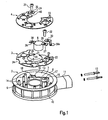
- FIG. 1 shows a housing part 2 made of plastic with an inner cylinder 7 and an outer cylinder 8. Both cylinders 7,8 are connected via a housing bottom 9. At the periphery of the outer cylinder 8 ribs 10 are arranged at a uniform spacing. In addition, a connection piece 11 for covering the electrical contact plug 12 is provided at one point. In the assembled state, the contact plug 12 protrude through two openings in the outer cylinder 8 into the interior of the housing 2.
- the bottom side 9 of the housing part 2 is flat, as are the upper edges of the inner and outer cylinders 7,8.
- a guide rail 38 is integrally formed. This runs parallel to the mounting direction A and serves to align the contact plates 3,4 during assembly.
- the retaining pins 14 are each identical in construction and especially arranged for the uniform attachment of the contact plates with respect to the heating elements 5.
- the orientation of the retaining pins 14 determines the Aufsteckutter A, in which the contact plates 3.4 are plugged.
- a total of twelve retaining pins 14 are provided.
- a portion 15 for receiving a thermostat body 6 is provided.
- two ringböcke 16,17 are arranged.
- In the RYböcken 16,17 on both sides of the section 15 holes 18,19 are provided for fixing the thermostat body 6 on the housing body 2.
- the entire housing 2 including the retaining pins 14 is a single component and may e.g. be made in a mold by spraying.
- the first contact plate 3 is plate-shaped and flat and describes a ring which is opened over about 90 °. Nevertheless, in order to make the first contact plate 2 rest on the largest possible circumference of the inner cylinder 7, the contact sections 21 are provided on the inner radius 20 of the first contact plate 3.
- the opening 22 is adapted to the size of the portion 15 which is intended to receive the thermostat body 6.
- a contact terminal 23 is provided, which is bent from the material of the first contact plate 3. Via guide sections 24 on the outer circumference, which engage with corresponding sections on the inner wall 13 of the outer cylinder 8, the position of the first contact plate 3 is additionally secured.
- the first contact plate 3 shows a total of twelve openings 25, which are intended to receive the twelve retaining pins 14 of the housing 2 and are tuned to their positions.
- the openings 25 are arrow-shaped, with the tips of the arrows pointing respectively to the center of the contact surface to the nearest heating element 5.
- the thermostat body 6 is substantially cylindrical and has at an upper end of the housing two oppositely projecting contact lugs 26,27, each with a bore hole 28,29. At the contact lug 27, a contact plate 30 is attached; this forms on the repellent from the thermostat body 6 end another contact terminal 30a.
- the boreholes 28, 29 are intended to receive screws 31, 32 which are screwed laterally to the section 15 for fixing the thermostat in the bores 18, 19 in the screw blocks 16, 17.
- the thermostat 6 comprises a bimetal switch, whereby the circuit is closed at about -2 ° C and at about + 5 ° C is opened.
- the second contact plate 4 is also plate-shaped, flat and annular and is interrupted over an area 40 of about 90 °.
- the openings 33 are matched to the retaining pins 14.
- a mounting portion 34 is bent up and provided with a borehole 35, which on the borehole 28 at the short holding portion 26 of the thermostat 6 is tuned.
- a guide portion 37 cooperates with a guide rail 38 on the inner side 13 of the outer cylinder 8 of the housing 2.
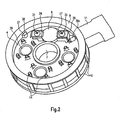
- FIG. 2 shows the heater in the assembled state.
- the thermostat body 6 is arranged in its intended position so that the cylinder axis extends substantially perpendicular to the contact plate planes.
- the contact plates 3,4 are mostly each flat and flat and thus each define a main plane that intersects the thermostat body 6 in the mounted state. Thus, for the space-saving accommodation of the thermostat body 6 in the interior of the housing 2, the "dead" space between the two contact plates 3,4 is utilized.
- the openings 33 in the second contact plate 4 are described below. They essentially show an H-profile and are arranged on circles at the center points of the heating elements 5. On two opposite sides of the spring tongues 36 are arranged, wherein the spring tongues 36 extend substantially tangentially to a circle around the nearest heating element 5.
- the cut-free spring tongues 36 each have sharp edges and are provided with barbs.
- the free ends of the spring tongues 36 are approximately adapted to the outer contour of the retaining pin 14 and concave.
- the particular for receiving the retaining pin 14, central opening of the opening 33 is dimensioned so that the opposite spring tongues 36 bend when plugging against the slip A direction.
- the second contact plate 4 extends, as well as the first contact plate 3, substantially in one plane.
- the circular contact surfaces 39 which protrude from the plane of the second contact plate 4 in the direction of the heating elements 5, are adapted in shape and size exactly the contact surfaces of the heating elements 5.
- the retaining pins 14 are distributed approximately uniformly around the circumference of these contact surfaces 39.
- the first contact plate 3 is attached to the retaining pins 14 until it comes to rest on a stop surface near the housing bottom 9.
- the guide section 37 is in this case with a corresponding, provided on the inner side 13 of the outer cylinder 8 guide rail 38 in engagement.
- the size of the holding openings 25 is determined so that the retaining pins 14 are bent slightly when plugging in a direction opposite to the respective arrow direction.
- the heating elements 5 are positioned on the designated places.
- four retaining pins 14 are provided per heating element 5 and arranged essentially on a circle around the respective nearest heating element 5.
- the thermostat 6 and the contact plate 30 is placed in the designated section 15 and first screwed with a screw 32 on one side with the provided screw 17.
- the contact terminals 23 and 30a thus lie directly next to one another and can receive the contact pins 12. In the assembled state thereby a conductive contact for heat and electricity between the second contact plate 4 and the thermostat 6 and the contact pin 12 is made on a holding portion 27 of the thermostat 6.
- the second contact plate 4 is plugged in Aufsteckcardi A on the retaining pins 14.
- the retaining pins 14 are tapered frustoconically at their free end. The tip of the retaining pins 14 fits in the undeformed state of the spring portions 26 exactly between the two spring tongues 26.
- the spring tongues 26 bend against the mounting direction A.
- the second contact plate 4 is pushed under the action of force on the retaining pins 14 and into abutment brought to all the heating elements 5.
- the retaining pins 14 are bent back into their original, straight shape and pressed in the arrow openings 25 of the first contact plate 4 against the flanks of the arrowheads.
- the first contact plate 3 is jammed against the retaining pins 14 and secured against wobbling.
- the spring tongues 26 of the second contact plate 4 clamp the respective holding pins 14. Since the retaining pins 14 are made of softer material than the spring tongues 26 and have sharp-edged cutting edges at the end, the spring tongues 26 become wedged and thus prevent a movement of the second contact plate 4 against the slip-on direction A.
- the screw 31 is for this purpose introduced into a corresponding borehole 35 which lies exactly above a borehole 28 in a holding section 26 of the thermostat 6 and is bolted to the screw block 16 laterally on the section 15.
- the second contact plate 4 and the thermostat 6 are firmly connected to the housing 2.
- the heater 1 can then be connected via the contact pins 12 to a circuit.
- Diesel fuel flows via the contact plates 3, 4 during operation.
- a bimetal switch closes the circuit and current flows through the assembly.
- the operation of such a thermostat 6 is assumed to be known and not explained in detail here.
- the heating elements 30 are so-called PTC (Positive-Temperature-Coefficient) elements, which act as resistors and convert electrical power into heat.
- the operation of such heating elements 5 is assumed to be known and not described here.
- the contact pressure between the heating elements 5 and the contact plates 3.4 is required.
- the bimetal switch opens the circuit as soon as the diesel fuel has reached a temperature of + 5 ° C or higher. Thus, no current flows through the assembly and the fuel is not heated further.
Landscapes
- Engineering & Computer Science (AREA)
- Chemical & Material Sciences (AREA)
- Combustion & Propulsion (AREA)
- Mechanical Engineering (AREA)
- General Engineering & Computer Science (AREA)
- Thermally Actuated Switches (AREA)
- Heating, Cooling, Or Curing Plastics Or The Like In General (AREA)
- Control Of Resistance Heating (AREA)
- Moulds For Moulding Plastics Or The Like (AREA)
- Tunnel Furnaces (AREA)
- Yarns And Mechanical Finishing Of Yarns Or Ropes (AREA)
Claims (6)
- Dispositif de chauffage (1) pour un fluide gazeux ou liquide à chauffer, comportant deux plaques de contact (3, 4) agencées dans un boîtier (2) et destinées à transmettre la chaleur, lesquelles sont agencées sensiblement parallèlement l'une à l'autre et s'étendent sensiblement chacune dans un plan et entre lesquelles au moins un élément chauffant (5) en forme de disque est agencé et est maintenu en appui contre les deux plaques de contact (3, 4), et un thermostat (6) qui est agencé à l'intérieur du boîtier et interrompt l'admission du courant vers l'élément chauffant (5) lorsqu'une température de service déterminée est atteinte, le boîtier du thermostat présentant une forme cylindrique et étant disposé de telle sorte que l'axe du cylindre formé par le boîtier de thermostat (6) est sensiblement perpendiculaire au plan des plaques de contact (3, 4), caractérisé en ce que le thermostat (6) est agencé dans le boîtier de telle sorte que le boîtier du thermostat coupe les plans des deux plaques de contact (3, 4), en ce que les plaques de contact (3, 4) sont sensiblement annulaires et présentent chacune une interruption (22, 40) de la forme annulaire, le thermostat (6) étant agencé au moins en partie à l'intérieur de ces interruptions (22, 40), et en ce que la différence entre le rayon extérieur et le rayon intérieur des plaques de contact (3, 4) annulaires correspond sensiblement au diamètre du boîtier du thermostat (6).
- Dispositif de chauffage (1) selon la revendication 1, caractérisé en ce que le thermostat (6) est relié de manière fixe à au moins une des plaques de contact (4) et comporte un raccord de contact (7) pour un circuit électrique, et l'autre plaque de contact (3), non reliée au thermostat (6), comporte un autre raccord de contact (8).
- Dispositif de chauffage (1) selon au moins l'une des revendications précédentes, caractérisé en ce que le thermostat (6) comporte un commutateur à deux points, de préférence un commutateur bimétallique, qui connecte automatiquement le dispositif de chauffage (1) en présence d'une température minimale déterminée mesurée, de préférence -2 °C, et le déconnecte automatiquement en présence d'une température maximale déterminée mesurée, de préférence +2 °C.
- Dispositif de chauffage (1) selon au moins l'une des revendications précédentes, caractérisé en ce que la première et la deuxième plaque de contact (3, 4) comportant chacune au moins un trou débouchant (25, 33), et le boîtier (2) comporte au moins un ergot de fixation (14), qui passe à travers les trous débouchants (25, 33) de la première et de la deuxième plaque de contact (3, 4).
- Dispositif de chauffage (1) selon au moins l'une des revendications précédentes, caractérisé en ce que quatre ergots de fixation (14) sont associés à chaque élément chauffant (5).
- Dispositif de chauffage (1) selon au moins l'une des revendications précédentes, caractérisé en ce que le boîtier (2) est réalisé en matière plastique.
Priority Applications (5)
| Application Number | Priority Date | Filing Date | Title |
|---|---|---|---|
| AT03019850T ATE390550T1 (de) | 2003-09-01 | 2003-09-01 | Heizeinrichtung für ein zu beheizendes medium |
| EP03019850A EP1510685B2 (fr) | 2003-09-01 | 2003-09-01 | Dispositif de chauffage pour un milieu à chauffer |
| DE50309473T DE50309473D1 (de) | 2003-09-01 | 2003-09-01 | Heizeinrichtung für ein zu beheizendes Medium |
| AU2003292143A AU2003292143A1 (en) | 2003-09-01 | 2003-11-27 | Heating device for heating a medium |
| PCT/EP2003/013375 WO2005031146A1 (fr) | 2003-09-01 | 2003-11-27 | Dispositif de chauffage pour fluide a chauffer |
Applications Claiming Priority (1)
| Application Number | Priority Date | Filing Date | Title |
|---|---|---|---|
| EP03019850A EP1510685B2 (fr) | 2003-09-01 | 2003-09-01 | Dispositif de chauffage pour un milieu à chauffer |
Publications (3)
| Publication Number | Publication Date |
|---|---|
| EP1510685A1 EP1510685A1 (fr) | 2005-03-02 |
| EP1510685B1 EP1510685B1 (fr) | 2008-03-26 |
| EP1510685B2 true EP1510685B2 (fr) | 2011-10-05 |
Family
ID=34089651
Family Applications (1)
| Application Number | Title | Priority Date | Filing Date |
|---|---|---|---|
| EP03019850A Expired - Lifetime EP1510685B2 (fr) | 2003-09-01 | 2003-09-01 | Dispositif de chauffage pour un milieu à chauffer |
Country Status (5)
| Country | Link |
|---|---|
| EP (1) | EP1510685B2 (fr) |
| AT (1) | ATE390550T1 (fr) |
| AU (1) | AU2003292143A1 (fr) |
| DE (1) | DE50309473D1 (fr) |
| WO (1) | WO2005031146A1 (fr) |
Families Citing this family (5)
| Publication number | Priority date | Publication date | Assignee | Title |
|---|---|---|---|---|
| DE202007017427U1 (de) * | 2007-12-13 | 2008-02-28 | Eichenauer Heizelemente Gmbh & Co. Kg | Kraftstoffvorwärmer mit Bimetallschalter |
| DE102008052918A1 (de) | 2007-12-21 | 2009-06-25 | Mahle International Gmbh | Heizeinrichtung für Kraftstoff |
| DE102009055084A1 (de) * | 2009-12-21 | 2011-06-22 | Robert Bosch GmbH, 70469 | Heizeinrichtung für einen Kraftstoff-Filter |
| DE102011000246A1 (de) | 2010-11-26 | 2012-05-31 | Dbk David + Baader Gmbh | Heizeinrichtung |
| EP2518301B1 (fr) * | 2011-04-27 | 2013-09-04 | sigmar S.r.l. | Tête de filtre à carburant avec chauffage intégré |
Citations (3)
| Publication number | Priority date | Publication date | Assignee | Title |
|---|---|---|---|---|
| EP0367631A1 (fr) † | 1988-11-04 | 1990-05-09 | Elmwood Sensors Limited | Réchauffeurs de carburant |
| WO2001092714A2 (fr) † | 2000-05-31 | 2001-12-06 | Parker-Hannifin Corporation | Ensemble de filtre a essence equipe d'une pompe d'amorcage |
| EP1316347A1 (fr) † | 2001-11-29 | 2003-06-04 | Robert Bosch Gmbh | Filtre à liquide pour purifier du carburant |
Family Cites Families (2)
| Publication number | Priority date | Publication date | Assignee | Title |
|---|---|---|---|---|
| EP0657199A2 (fr) * | 1993-12-13 | 1995-06-14 | Stanadyne Automotive Corp. | Module de chauffage pour ensemble filtrant |
| DE50014999D1 (de) * | 2000-05-25 | 2008-04-10 | Dbk David & Baader Gmbh | PTC-Heizeinrichtung |
-
2003
- 2003-09-01 AT AT03019850T patent/ATE390550T1/de not_active IP Right Cessation
- 2003-09-01 DE DE50309473T patent/DE50309473D1/de not_active Expired - Lifetime
- 2003-09-01 EP EP03019850A patent/EP1510685B2/fr not_active Expired - Lifetime
- 2003-11-27 WO PCT/EP2003/013375 patent/WO2005031146A1/fr not_active Ceased
- 2003-11-27 AU AU2003292143A patent/AU2003292143A1/en not_active Abandoned
Patent Citations (3)
| Publication number | Priority date | Publication date | Assignee | Title |
|---|---|---|---|---|
| EP0367631A1 (fr) † | 1988-11-04 | 1990-05-09 | Elmwood Sensors Limited | Réchauffeurs de carburant |
| WO2001092714A2 (fr) † | 2000-05-31 | 2001-12-06 | Parker-Hannifin Corporation | Ensemble de filtre a essence equipe d'une pompe d'amorcage |
| EP1316347A1 (fr) † | 2001-11-29 | 2003-06-04 | Robert Bosch Gmbh | Filtre à liquide pour purifier du carburant |
Also Published As
| Publication number | Publication date |
|---|---|
| EP1510685B1 (fr) | 2008-03-26 |
| WO2005031146A1 (fr) | 2005-04-07 |
| AU2003292143A1 (en) | 2005-04-14 |
| ATE390550T1 (de) | 2008-04-15 |
| DE50309473D1 (de) | 2008-05-08 |
| EP1510685A1 (fr) | 2005-03-02 |
Similar Documents
| Publication | Publication Date | Title |
|---|---|---|
| DE102004002905B4 (de) | Glühkerzenstecker | |
| EP1491296B1 (fr) | Elément de raccord | |
| EP3336969B1 (fr) | Dispositif de contact pour une transmission d'énergie électrique sur une carte de circuits imprimés et procédé de montage d'un tel dispositif de contacts | |
| DE19726496B4 (de) | Anlasser für eine Brennkraftmaschine | |
| EP2198490B1 (fr) | Ensemble balai et machine electrique, notamment appareil menager electrique | |
| EP1510685B2 (fr) | Dispositif de chauffage pour un milieu à chauffer | |
| EP0581176B1 (fr) | Dispositif de réchauffage électrique pour carburant diesel | |
| EP1215763A1 (fr) | Contact femelle pour un connecteur électrique | |
| DE3801410A1 (de) | Kraftstoffaufbereitungsvorrichtung | |
| DE19948716C1 (de) | Anordnung zur Lagerung der Schaltwelle eines Niederspannungs-Leistungsschalters und mehrpoliger Niederspannungs-Leistungsschalter mit eienr Anordnung zur Lagerung der Schaltwelle | |
| DE3538546C2 (fr) | ||
| EP0827167B1 (fr) | Interrupteur électrique en particulier pour véhicules | |
| EP1353131A2 (fr) | Dispositif de chauffage électrique, spécialement pour une voiture | |
| EP1510688B1 (fr) | Dispositif de chauffage pour un milieu à chauffer | |
| DE4121575C1 (fr) | ||
| DE102009049407A1 (de) | Elektroinstallationsgerät mit einstellbarem Schaltelement | |
| DE69105325T2 (de) | Zündanlage für innere Brennkraftmaschine. | |
| DE3441575A1 (de) | Elektrothermische ventileinstellantriebsvorrichtung | |
| EP1548895A2 (fr) | Disposition de montage de connecteur électrique | |
| EP1480793A1 (fr) | Dispositif de coupe universel comportant un interrupteur de securite | |
| EP1628371B1 (fr) | Dispositif de connection électrique | |
| DE2805182B1 (de) | Einstellvorrichtung fuer den Ausloeser eines elektrischen Schaltgeraetes | |
| DE102011089016A1 (de) | Drehwahlschalter und Verfahren zum Herstellen eines Drehwahlschalters | |
| DE29800670U1 (de) | Leuchtenhalterung | |
| DE202019105448U1 (de) | Schalterbaugruppe mit Begrenzungsfunktion |
Legal Events
| Date | Code | Title | Description |
|---|---|---|---|
| PUAI | Public reference made under article 153(3) epc to a published international application that has entered the european phase |
Free format text: ORIGINAL CODE: 0009012 |
|
| AK | Designated contracting states |
Kind code of ref document: A1 Designated state(s): AT BE BG CH CY CZ DE DK EE ES FI FR GB GR HU IE IT LI LU MC NL PT RO SE SI SK TR |
|
| AX | Request for extension of the european patent |
Extension state: AL LT LV MK |
|
| RAP1 | Party data changed (applicant data changed or rights of an application transferred) |
Owner name: DBK DAVID + BAADER GMBH |
|
| 17P | Request for examination filed |
Effective date: 20050323 |
|
| AKX | Designation fees paid |
Designated state(s): AT BE BG CH CY CZ DE DK EE ES FI FR GB GR HU IE IT LI LU MC NL PT RO SE SI SK TR |
|
| 17Q | First examination report despatched |
Effective date: 20061228 |
|
| GRAP | Despatch of communication of intention to grant a patent |
Free format text: ORIGINAL CODE: EPIDOSNIGR1 |
|
| GRAS | Grant fee paid |
Free format text: ORIGINAL CODE: EPIDOSNIGR3 |
|
| GRAA | (expected) grant |
Free format text: ORIGINAL CODE: 0009210 |
|
| AK | Designated contracting states |
Kind code of ref document: B1 Designated state(s): AT BE BG CH CY CZ DE DK EE ES FI FR GB GR HU IE IT LI LU MC NL PT RO SE SI SK TR |
|
| REG | Reference to a national code |
Ref country code: GB Ref legal event code: FG4D Free format text: NOT ENGLISH |
|
| REG | Reference to a national code |
Ref country code: CH Ref legal event code: EP Ref country code: IE Ref legal event code: FG4D Free format text: LANGUAGE OF EP DOCUMENT: GERMAN |
|
| REF | Corresponds to: |
Ref document number: 50309473 Country of ref document: DE Date of ref document: 20080508 Kind code of ref document: P |
|
| PG25 | Lapsed in a contracting state [announced via postgrant information from national office to epo] |
Ref country code: FI Free format text: LAPSE BECAUSE OF FAILURE TO SUBMIT A TRANSLATION OF THE DESCRIPTION OR TO PAY THE FEE WITHIN THE PRESCRIBED TIME-LIMIT Effective date: 20080326 |
|
| NLV1 | Nl: lapsed or annulled due to failure to fulfill the requirements of art. 29p and 29m of the patents act | ||
| PG25 | Lapsed in a contracting state [announced via postgrant information from national office to epo] |
Ref country code: SI Free format text: LAPSE BECAUSE OF FAILURE TO SUBMIT A TRANSLATION OF THE DESCRIPTION OR TO PAY THE FEE WITHIN THE PRESCRIBED TIME-LIMIT Effective date: 20080326 |
|
| REG | Reference to a national code |
Ref country code: IE Ref legal event code: FD4D |
|
| PG25 | Lapsed in a contracting state [announced via postgrant information from national office to epo] |
Ref country code: ES Free format text: LAPSE BECAUSE OF FAILURE TO SUBMIT A TRANSLATION OF THE DESCRIPTION OR TO PAY THE FEE WITHIN THE PRESCRIBED TIME-LIMIT Effective date: 20080707 Ref country code: PT Free format text: LAPSE BECAUSE OF FAILURE TO SUBMIT A TRANSLATION OF THE DESCRIPTION OR TO PAY THE FEE WITHIN THE PRESCRIBED TIME-LIMIT Effective date: 20080901 Ref country code: CZ Free format text: LAPSE BECAUSE OF FAILURE TO SUBMIT A TRANSLATION OF THE DESCRIPTION OR TO PAY THE FEE WITHIN THE PRESCRIBED TIME-LIMIT Effective date: 20080326 Ref country code: SE Free format text: LAPSE BECAUSE OF FAILURE TO SUBMIT A TRANSLATION OF THE DESCRIPTION OR TO PAY THE FEE WITHIN THE PRESCRIBED TIME-LIMIT Effective date: 20080626 Ref country code: SK Free format text: LAPSE BECAUSE OF FAILURE TO SUBMIT A TRANSLATION OF THE DESCRIPTION OR TO PAY THE FEE WITHIN THE PRESCRIBED TIME-LIMIT Effective date: 20080326 |
|
| PG25 | Lapsed in a contracting state [announced via postgrant information from national office to epo] |
Ref country code: NL Free format text: LAPSE BECAUSE OF FAILURE TO SUBMIT A TRANSLATION OF THE DESCRIPTION OR TO PAY THE FEE WITHIN THE PRESCRIBED TIME-LIMIT Effective date: 20080326 Ref country code: RO Free format text: LAPSE BECAUSE OF FAILURE TO SUBMIT A TRANSLATION OF THE DESCRIPTION OR TO PAY THE FEE WITHIN THE PRESCRIBED TIME-LIMIT Effective date: 20080326 |
|
| ET | Fr: translation filed | ||
| PLBI | Opposition filed |
Free format text: ORIGINAL CODE: 0009260 |
|
| 26 | Opposition filed |
Opponent name: EICHENAUER HEIZELEMENTE GMBH & CO.KG Effective date: 20081218 |
|
| PLAX | Notice of opposition and request to file observation + time limit sent |
Free format text: ORIGINAL CODE: EPIDOSNOBS2 |
|
| PG25 | Lapsed in a contracting state [announced via postgrant information from national office to epo] |
Ref country code: DK Free format text: LAPSE BECAUSE OF FAILURE TO SUBMIT A TRANSLATION OF THE DESCRIPTION OR TO PAY THE FEE WITHIN THE PRESCRIBED TIME-LIMIT Effective date: 20080326 Ref country code: IE Free format text: LAPSE BECAUSE OF FAILURE TO SUBMIT A TRANSLATION OF THE DESCRIPTION OR TO PAY THE FEE WITHIN THE PRESCRIBED TIME-LIMIT Effective date: 20080326 |
|
| PLBB | Reply of patent proprietor to notice(s) of opposition received |
Free format text: ORIGINAL CODE: EPIDOSNOBS3 |
|
| BERE | Be: lapsed |
Owner name: DBK DAVID + BAADER G.M.B.H. Effective date: 20080930 |
|
| PG25 | Lapsed in a contracting state [announced via postgrant information from national office to epo] |
Ref country code: MC Free format text: LAPSE BECAUSE OF NON-PAYMENT OF DUE FEES Effective date: 20080930 Ref country code: BG Free format text: LAPSE BECAUSE OF FAILURE TO SUBMIT A TRANSLATION OF THE DESCRIPTION OR TO PAY THE FEE WITHIN THE PRESCRIBED TIME-LIMIT Effective date: 20080626 Ref country code: EE Free format text: LAPSE BECAUSE OF FAILURE TO SUBMIT A TRANSLATION OF THE DESCRIPTION OR TO PAY THE FEE WITHIN THE PRESCRIBED TIME-LIMIT Effective date: 20080326 |
|
| REG | Reference to a national code |
Ref country code: CH Ref legal event code: PL |
|
| PG25 | Lapsed in a contracting state [announced via postgrant information from national office to epo] |
Ref country code: BE Free format text: LAPSE BECAUSE OF NON-PAYMENT OF DUE FEES Effective date: 20080930 |
|
| PG25 | Lapsed in a contracting state [announced via postgrant information from national office to epo] |
Ref country code: IT Free format text: LAPSE BECAUSE OF FAILURE TO SUBMIT A TRANSLATION OF THE DESCRIPTION OR TO PAY THE FEE WITHIN THE PRESCRIBED TIME-LIMIT Effective date: 20080326 |
|
| PG25 | Lapsed in a contracting state [announced via postgrant information from national office to epo] |
Ref country code: CY Free format text: LAPSE BECAUSE OF FAILURE TO SUBMIT A TRANSLATION OF THE DESCRIPTION OR TO PAY THE FEE WITHIN THE PRESCRIBED TIME-LIMIT Effective date: 20080326 |
|
| PG25 | Lapsed in a contracting state [announced via postgrant information from national office to epo] |
Ref country code: AT Free format text: LAPSE BECAUSE OF NON-PAYMENT OF DUE FEES Effective date: 20080901 Ref country code: LI Free format text: LAPSE BECAUSE OF NON-PAYMENT OF DUE FEES Effective date: 20080930 Ref country code: CH Free format text: LAPSE BECAUSE OF NON-PAYMENT OF DUE FEES Effective date: 20080930 |
|
| PG25 | Lapsed in a contracting state [announced via postgrant information from national office to epo] |
Ref country code: LU Free format text: LAPSE BECAUSE OF NON-PAYMENT OF DUE FEES Effective date: 20080901 Ref country code: HU Free format text: LAPSE BECAUSE OF FAILURE TO SUBMIT A TRANSLATION OF THE DESCRIPTION OR TO PAY THE FEE WITHIN THE PRESCRIBED TIME-LIMIT Effective date: 20080927 |
|
| PG25 | Lapsed in a contracting state [announced via postgrant information from national office to epo] |
Ref country code: TR Free format text: LAPSE BECAUSE OF FAILURE TO SUBMIT A TRANSLATION OF THE DESCRIPTION OR TO PAY THE FEE WITHIN THE PRESCRIBED TIME-LIMIT Effective date: 20080326 |
|
| PG25 | Lapsed in a contracting state [announced via postgrant information from national office to epo] |
Ref country code: GR Free format text: LAPSE BECAUSE OF FAILURE TO SUBMIT A TRANSLATION OF THE DESCRIPTION OR TO PAY THE FEE WITHIN THE PRESCRIBED TIME-LIMIT Effective date: 20080627 |
|
| PUAH | Patent maintained in amended form |
Free format text: ORIGINAL CODE: 0009272 |
|
| STAA | Information on the status of an ep patent application or granted ep patent |
Free format text: STATUS: PATENT MAINTAINED AS AMENDED |
|
| 27A | Patent maintained in amended form |
Effective date: 20111005 |
|
| AK | Designated contracting states |
Kind code of ref document: B2 Designated state(s): AT BE BG CH CY CZ DE DK EE ES FI FR GB GR HU IE IT LI LU MC NL PT RO SE SI SK TR |
|
| REG | Reference to a national code |
Ref country code: DE Ref legal event code: R102 Ref document number: 50309473 Country of ref document: DE |
|
| REG | Reference to a national code |
Ref country code: DE Ref legal event code: R102 Ref document number: 50309473 Country of ref document: DE Effective date: 20111005 |
|
| REG | Reference to a national code |
Ref country code: DE Ref legal event code: R082 Ref document number: 50309473 Country of ref document: DE Representative=s name: WINTER, BRANDL, FUERNISS, HUEBNER, ROESS, KAIS, DE |
|
| REG | Reference to a national code |
Ref country code: DE Ref legal event code: R081 Ref document number: 50309473 Country of ref document: DE Owner name: DBK DAVID + BAADER GMBH, DE Free format text: FORMER OWNER: DBK DAVID + BAADER GMBH, 76870 KANDEL, DE Effective date: 20130807 Ref country code: DE Ref legal event code: R082 Ref document number: 50309473 Country of ref document: DE Representative=s name: WINTER, BRANDL, FUERNISS, HUEBNER, ROESS, KAIS, DE Effective date: 20130807 |
|
| REG | Reference to a national code |
Ref country code: FR Ref legal event code: PLFP Year of fee payment: 14 |
|
| PGFP | Annual fee paid to national office [announced via postgrant information from national office to epo] |
Ref country code: GB Payment date: 20160921 Year of fee payment: 14 Ref country code: DE Payment date: 20160824 Year of fee payment: 14 |
|
| REG | Reference to a national code |
Ref country code: DE Ref legal event code: R082 Ref document number: 50309473 Country of ref document: DE Representative=s name: WINTER, BRANDL - PARTNERSCHAFT MBB, PATENTANWA, DE Ref country code: DE Ref legal event code: R082 Ref document number: 50309473 Country of ref document: DE Representative=s name: WINTER, BRANDL, FUERNISS, HUEBNER, ROESS, KAIS, DE |
|
| PGFP | Annual fee paid to national office [announced via postgrant information from national office to epo] |
Ref country code: FR Payment date: 20160922 Year of fee payment: 14 |
|
| REG | Reference to a national code |
Ref country code: DE Ref legal event code: R119 Ref document number: 50309473 Country of ref document: DE |
|
| GBPC | Gb: european patent ceased through non-payment of renewal fee |
Effective date: 20170901 |
|
| REG | Reference to a national code |
Ref country code: FR Ref legal event code: ST Effective date: 20180531 |
|
| PG25 | Lapsed in a contracting state [announced via postgrant information from national office to epo] |
Ref country code: DE Free format text: LAPSE BECAUSE OF NON-PAYMENT OF DUE FEES Effective date: 20180404 Ref country code: GB Free format text: LAPSE BECAUSE OF NON-PAYMENT OF DUE FEES Effective date: 20170901 |
|
| PG25 | Lapsed in a contracting state [announced via postgrant information from national office to epo] |
Ref country code: FR Free format text: LAPSE BECAUSE OF NON-PAYMENT OF DUE FEES Effective date: 20171002 |