EP1510685B2 - Heating device for a medium to be heated - Google Patents
Heating device for a medium to be heated Download PDFInfo
- Publication number
- EP1510685B2 EP1510685B2 EP03019850A EP03019850A EP1510685B2 EP 1510685 B2 EP1510685 B2 EP 1510685B2 EP 03019850 A EP03019850 A EP 03019850A EP 03019850 A EP03019850 A EP 03019850A EP 1510685 B2 EP1510685 B2 EP 1510685B2
- Authority
- EP
- European Patent Office
- Prior art keywords
- thermostat
- housing
- contact
- heating device
- contact plates
- Prior art date
- Legal status (The legal status is an assumption and is not a legal conclusion. Google has not performed a legal analysis and makes no representation as to the accuracy of the status listed.)
- Expired - Lifetime
Links
Images
Classifications
-
- F—MECHANICAL ENGINEERING; LIGHTING; HEATING; WEAPONS; BLASTING
- F23—COMBUSTION APPARATUS; COMBUSTION PROCESSES
- F23K—FEEDING FUEL TO COMBUSTION APPARATUS
- F23K5/00—Feeding or distributing other fuel to combustion apparatus
- F23K5/02—Liquid fuel
- F23K5/14—Details thereof
- F23K5/20—Preheating devices
-
- F—MECHANICAL ENGINEERING; LIGHTING; HEATING; WEAPONS; BLASTING
- F02—COMBUSTION ENGINES; HOT-GAS OR COMBUSTION-PRODUCT ENGINE PLANTS
- F02M—SUPPLYING COMBUSTION ENGINES IN GENERAL WITH COMBUSTIBLE MIXTURES OR CONSTITUENTS THEREOF
- F02M31/00—Apparatus for thermally treating combustion-air, fuel, or fuel-air mixture
- F02M31/02—Apparatus for thermally treating combustion-air, fuel, or fuel-air mixture for heating
- F02M31/12—Apparatus for thermally treating combustion-air, fuel, or fuel-air mixture for heating electrically
- F02M31/125—Fuel
-
- F—MECHANICAL ENGINEERING; LIGHTING; HEATING; WEAPONS; BLASTING
- F02—COMBUSTION ENGINES; HOT-GAS OR COMBUSTION-PRODUCT ENGINE PLANTS
- F02M—SUPPLYING COMBUSTION ENGINES IN GENERAL WITH COMBUSTIBLE MIXTURES OR CONSTITUENTS THEREOF
- F02M37/00—Apparatus or systems for feeding liquid fuel from storage containers to carburettors or fuel-injection apparatus; Arrangements for purifying liquid fuel specially adapted for, or arranged on, internal-combustion engines
- F02M37/22—Arrangements for purifying liquid fuel specially adapted for, or arranged on, internal-combustion engines, e.g. arrangements in the feeding system
- F02M37/30—Arrangements for purifying liquid fuel specially adapted for, or arranged on, internal-combustion engines, e.g. arrangements in the feeding system characterised by heating means
-
- Y—GENERAL TAGGING OF NEW TECHNOLOGICAL DEVELOPMENTS; GENERAL TAGGING OF CROSS-SECTIONAL TECHNOLOGIES SPANNING OVER SEVERAL SECTIONS OF THE IPC; TECHNICAL SUBJECTS COVERED BY FORMER USPC CROSS-REFERENCE ART COLLECTIONS [XRACs] AND DIGESTS
- Y02—TECHNOLOGIES OR APPLICATIONS FOR MITIGATION OR ADAPTATION AGAINST CLIMATE CHANGE
- Y02T—CLIMATE CHANGE MITIGATION TECHNOLOGIES RELATED TO TRANSPORTATION
- Y02T10/00—Road transport of goods or passengers
- Y02T10/10—Internal combustion engine [ICE] based vehicles
- Y02T10/12—Improving ICE efficiencies
Definitions
- the invention relates to a heating device for a gaseous or liquid medium to be heated according to the preamble of claim 1.
- Such a heater is from the EP 0 657 199 A2 known.
- the US 4,406,785 shows a heater which is integrated in a housing part of a fuel filter.
- This heater essentially shows two superimposed annular contact plates with a plurality of heating elements in the intermediate space.
- the contact plates extend substantially in each case in a plane and are arranged parallel to each other. From the plane of a contact plate stand out individual spring sections.
- a contact piece for connection to an electrical circuit extends from the surface of a heater housing, which is arranged parallel to the two contact plates.
- a thermostat for interrupting the circuit when reaching a certain operating temperature can be integrated into the contact piece.
- Such heaters have been used successfully for many years, yet the demands placed on such heating systems are constantly increasing. In particular, the market demands ever smaller, less expensive components with essentially the same functionality and reliability. In addition, such a heater to reduce energy consumption can be operated even more economical.
- the invention is therefore based on the object to significantly reduce the space consumption of a heater of the type mentioned and to improve the response of a thermostat.
- the object is achieved by the heating device according to claim 1, wherein the thermostat is arranged in the housing so that the thermostat housing intersects the plane of both contact plates.
- the "dead" space between the main planes of the two contact plates is ideally utilized.
- the entire arrangement is thus extremely compact and can be installed in a very small volume.
- the thermostat body protrudes into the space between the contact plates, he is thus at least partially in the immediate vicinity of the heating element.
- a rapid response is desirable, which is made possible by the solution according to the invention.
- the contact plates are substantially annular and arranged substantially parallel to each other.
- the heating device according to the invention is suitable for installation in the most common fuel filter.
- An annular contact plate has an interruption of the ring shape, wherein the thermostat is at least partially disposed within this interruption.
- the ring shape of the contact plates results from the double cylindrical filter housing form with an outer cylinder and an inner cylinder, through which the filtered fuel is led to the fuel drain of the filter housing.
- the thermostat housing has a cylindrical shape and is arranged so that the cylinder axis of the thermostat housing extends substantially perpendicular to the plane of the contact plate.
- the difference between the outer and inner radius of the annular contact plate substantially corresponds to the diameter of the thermostat housing.
- the thermostat fits exactly in the space between the outer and the inner cylinder of a fuel filter housing.
- the thermostat is fixedly connected to at least one of the contact plates and has a contact terminal for an electrical circuit, wherein the other, not connected to the thermostat contact plate having a further contact terminal. Over the firm connection of the thermostat with one of the two contact plates, a good conductive, electrical connection is ensured during operation.
- thermostat Two-point switch preferably a bimetallic switch, which automatically turns on the heater at a certain measured minimum temperature, preferably -2 ° C, and at a certain measured maximum temperature, preferably + 5 ° C, automatically turns off. If the ambient conditions do not require it, the fuel will not be unnecessarily heated and power will be saved.
- the heater is thus particularly well suited for the heating of engine operating materials.
- first and the second contact plate is provided with at least one opening, and the housing has at least one retaining pin which penetrates the openings of the first and the second contact plate.
- This holding mechanism is compact and produces a high contact pressure with few components. The heater can thus be made even more compact overall.
- the arrangement becomes particularly stable if at least three retaining pins are provided per heating element. The position of the heating element is thus secured against slipping in the space between the contact plates.
- plastics are generally inexpensive to buy, and the shape of plastic products is relatively simple. As a rule, plastics also act as an insulator for heat and electricity. Thus, e.g. unwanted heat loss through the housing can be prevented.
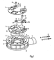
- FIG. 1 shows a housing part 2 made of plastic with an inner cylinder 7 and an outer cylinder 8. Both cylinders 7,8 are connected via a housing bottom 9. At the periphery of the outer cylinder 8 ribs 10 are arranged at a uniform spacing. In addition, a connection piece 11 for covering the electrical contact plug 12 is provided at one point. In the assembled state, the contact plug 12 protrude through two openings in the outer cylinder 8 into the interior of the housing 2.
- the bottom side 9 of the housing part 2 is flat, as are the upper edges of the inner and outer cylinders 7,8.
- a guide rail 38 is integrally formed. This runs parallel to the mounting direction A and serves to align the contact plates 3,4 during assembly.
- the retaining pins 14 are each identical in construction and especially arranged for the uniform attachment of the contact plates with respect to the heating elements 5.
- the orientation of the retaining pins 14 determines the Aufsteckutter A, in which the contact plates 3.4 are plugged.
- a total of twelve retaining pins 14 are provided.
- a portion 15 for receiving a thermostat body 6 is provided.
- two ringböcke 16,17 are arranged.
- In the RYböcken 16,17 on both sides of the section 15 holes 18,19 are provided for fixing the thermostat body 6 on the housing body 2.
- the entire housing 2 including the retaining pins 14 is a single component and may e.g. be made in a mold by spraying.
- the first contact plate 3 is plate-shaped and flat and describes a ring which is opened over about 90 °. Nevertheless, in order to make the first contact plate 2 rest on the largest possible circumference of the inner cylinder 7, the contact sections 21 are provided on the inner radius 20 of the first contact plate 3.
- the opening 22 is adapted to the size of the portion 15 which is intended to receive the thermostat body 6.
- a contact terminal 23 is provided, which is bent from the material of the first contact plate 3. Via guide sections 24 on the outer circumference, which engage with corresponding sections on the inner wall 13 of the outer cylinder 8, the position of the first contact plate 3 is additionally secured.
- the first contact plate 3 shows a total of twelve openings 25, which are intended to receive the twelve retaining pins 14 of the housing 2 and are tuned to their positions.
- the openings 25 are arrow-shaped, with the tips of the arrows pointing respectively to the center of the contact surface to the nearest heating element 5.
- the thermostat body 6 is substantially cylindrical and has at an upper end of the housing two oppositely projecting contact lugs 26,27, each with a bore hole 28,29. At the contact lug 27, a contact plate 30 is attached; this forms on the repellent from the thermostat body 6 end another contact terminal 30a.
- the boreholes 28, 29 are intended to receive screws 31, 32 which are screwed laterally to the section 15 for fixing the thermostat in the bores 18, 19 in the screw blocks 16, 17.
- the thermostat 6 comprises a bimetal switch, whereby the circuit is closed at about -2 ° C and at about + 5 ° C is opened.
- the second contact plate 4 is also plate-shaped, flat and annular and is interrupted over an area 40 of about 90 °.
- the openings 33 are matched to the retaining pins 14.
- a mounting portion 34 is bent up and provided with a borehole 35, which on the borehole 28 at the short holding portion 26 of the thermostat 6 is tuned.
- a guide portion 37 cooperates with a guide rail 38 on the inner side 13 of the outer cylinder 8 of the housing 2.
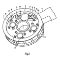
- FIG. 2 shows the heater in the assembled state.
- the thermostat body 6 is arranged in its intended position so that the cylinder axis extends substantially perpendicular to the contact plate planes.
- the contact plates 3,4 are mostly each flat and flat and thus each define a main plane that intersects the thermostat body 6 in the mounted state. Thus, for the space-saving accommodation of the thermostat body 6 in the interior of the housing 2, the "dead" space between the two contact plates 3,4 is utilized.
- the openings 33 in the second contact plate 4 are described below. They essentially show an H-profile and are arranged on circles at the center points of the heating elements 5. On two opposite sides of the spring tongues 36 are arranged, wherein the spring tongues 36 extend substantially tangentially to a circle around the nearest heating element 5.
- the cut-free spring tongues 36 each have sharp edges and are provided with barbs.
- the free ends of the spring tongues 36 are approximately adapted to the outer contour of the retaining pin 14 and concave.
- the particular for receiving the retaining pin 14, central opening of the opening 33 is dimensioned so that the opposite spring tongues 36 bend when plugging against the slip A direction.
- the second contact plate 4 extends, as well as the first contact plate 3, substantially in one plane.
- the circular contact surfaces 39 which protrude from the plane of the second contact plate 4 in the direction of the heating elements 5, are adapted in shape and size exactly the contact surfaces of the heating elements 5.
- the retaining pins 14 are distributed approximately uniformly around the circumference of these contact surfaces 39.
- the first contact plate 3 is attached to the retaining pins 14 until it comes to rest on a stop surface near the housing bottom 9.
- the guide section 37 is in this case with a corresponding, provided on the inner side 13 of the outer cylinder 8 guide rail 38 in engagement.
- the size of the holding openings 25 is determined so that the retaining pins 14 are bent slightly when plugging in a direction opposite to the respective arrow direction.
- the heating elements 5 are positioned on the designated places.
- four retaining pins 14 are provided per heating element 5 and arranged essentially on a circle around the respective nearest heating element 5.
- the thermostat 6 and the contact plate 30 is placed in the designated section 15 and first screwed with a screw 32 on one side with the provided screw 17.
- the contact terminals 23 and 30a thus lie directly next to one another and can receive the contact pins 12. In the assembled state thereby a conductive contact for heat and electricity between the second contact plate 4 and the thermostat 6 and the contact pin 12 is made on a holding portion 27 of the thermostat 6.
- the second contact plate 4 is plugged in Aufsteckcardi A on the retaining pins 14.
- the retaining pins 14 are tapered frustoconically at their free end. The tip of the retaining pins 14 fits in the undeformed state of the spring portions 26 exactly between the two spring tongues 26.
- the spring tongues 26 bend against the mounting direction A.
- the second contact plate 4 is pushed under the action of force on the retaining pins 14 and into abutment brought to all the heating elements 5.
- the retaining pins 14 are bent back into their original, straight shape and pressed in the arrow openings 25 of the first contact plate 4 against the flanks of the arrowheads.
- the first contact plate 3 is jammed against the retaining pins 14 and secured against wobbling.
- the spring tongues 26 of the second contact plate 4 clamp the respective holding pins 14. Since the retaining pins 14 are made of softer material than the spring tongues 26 and have sharp-edged cutting edges at the end, the spring tongues 26 become wedged and thus prevent a movement of the second contact plate 4 against the slip-on direction A.
- the screw 31 is for this purpose introduced into a corresponding borehole 35 which lies exactly above a borehole 28 in a holding section 26 of the thermostat 6 and is bolted to the screw block 16 laterally on the section 15.
- the second contact plate 4 and the thermostat 6 are firmly connected to the housing 2.
- the heater 1 can then be connected via the contact pins 12 to a circuit.
- Diesel fuel flows via the contact plates 3, 4 during operation.
- a bimetal switch closes the circuit and current flows through the assembly.
- the operation of such a thermostat 6 is assumed to be known and not explained in detail here.
- the heating elements 30 are so-called PTC (Positive-Temperature-Coefficient) elements, which act as resistors and convert electrical power into heat.
- the operation of such heating elements 5 is assumed to be known and not described here.
- the contact pressure between the heating elements 5 and the contact plates 3.4 is required.
- the bimetal switch opens the circuit as soon as the diesel fuel has reached a temperature of + 5 ° C or higher. Thus, no current flows through the assembly and the fuel is not heated further.
Landscapes
- Engineering & Computer Science (AREA)
- Chemical & Material Sciences (AREA)
- Combustion & Propulsion (AREA)
- Mechanical Engineering (AREA)
- General Engineering & Computer Science (AREA)
- Heating, Cooling, Or Curing Plastics Or The Like In General (AREA)
- Thermally Actuated Switches (AREA)
- Tunnel Furnaces (AREA)
- Control Of Resistance Heating (AREA)
- Yarns And Mechanical Finishing Of Yarns Or Ropes (AREA)
- Moulds For Moulding Plastics Or The Like (AREA)
Abstract
Description
Die Erfindung betrifft eine Heizeinrichtung für ein gasförmiges oder flüssiges zu beheizendes Medium gemäß dem Oberbegriff des Anspruchs 1.The invention relates to a heating device for a gaseous or liquid medium to be heated according to the preamble of claim 1.
Eine derartige Heizeinrichtung ist aus der
Die
Solche Heizeinrichtungen werden seit vielen Jahren erfolgreich eingesetzt, dennoch wachsen die Anforderungen, die an solche Heizsysteme gestellt werden ständig. So verlangt der Markt insbesondere nach immer kleineren, kostengünstigeren Bauteilen bei im Wesentlichen gleichbleibender Funktionalität und Zuverlässigkeit. Zudem soll eine derartige Heizeinrichtung zur Reduzierung des Energieverbrauchs noch ökonomischer betrieben werden können.Such heaters have been used successfully for many years, yet the demands placed on such heating systems are constantly increasing. In particular, the market demands ever smaller, less expensive components with essentially the same functionality and reliability. In addition, such a heater to reduce energy consumption can be operated even more economical.
Der Erfindung liegt dadurch die Aufgabe zugrunde, den Platzverbrauch einer Heizeinrichtung der eingangs erwähnten Art erheblich zu reduzieren und das Ansprechverhalten eines Thermostaten zu verbessern.The invention is therefore based on the object to significantly reduce the space consumption of a heater of the type mentioned and to improve the response of a thermostat.
Die Aufgabe wird durch die Heizeinrichtung nach Anspruch 1 gelöst, wobei der Thermostat im Gehäuse so angeordnet ist, dass das Thermostatgehäuse die Ebene beider Kontaktplatten schneidet.The object is achieved by the heating device according to claim 1, wherein the thermostat is arranged in the housing so that the thermostat housing intersects the plane of both contact plates.
So wird, für die platzsparende Unterbringung des Thermostatkörpers im Inneren des Gehäuses, der "tote" Raum zwischen den Hauptebenen der beiden Kontaktplatten ideal ausgenutzt. Die gesamte Anordnung ist dadurch außerordentlich kompakt und lässt sich in sehr kleinem Volumen einbauen. Dadurch, dass der Thermostatkörper in den Raum zwischen den Kontaktplatten hineinragt, befindet er sich damit zumindest abschnittsweise in der unmittelbaren Nähe des Heizelements. Gerade bei Thermostaten mit kleinem Betriebsbereich z.B. (-2°C/+5°C) ist ein rasches Ansprechverhalten wünschenswert, was durch die erfindungsgemäße Lösung ermöglicht wird.Thus, for the space-saving accommodation of the thermostat body inside the housing, the "dead" space between the main planes of the two contact plates is ideally utilized. The entire arrangement is thus extremely compact and can be installed in a very small volume. Characterized in that the thermostat body protrudes into the space between the contact plates, he is thus at least partially in the immediate vicinity of the heating element. Especially with thermostats with a small operating range, e.g. (-2 ° C / + 5 ° C), a rapid response is desirable, which is made possible by the solution according to the invention.
Die Kontaktplatten sind im Wesentlichen ringförmig und im Wesentlichen parallel zueinander angeordnet. Dadurch eignet sich die erfindungsgemäße Heizeinrichtung für den Einbau in die meisten gängigen Kraftstofffilter.The contact plates are substantially annular and arranged substantially parallel to each other. As a result, the heating device according to the invention is suitable for installation in the most common fuel filter.
Eine ringförmige Kontaktplatte weist eine Unterbrechung der Ringform auf, wobei der Thermostat zumindest abschnittsweise innerhalb dieser Unterbrechung angeordnet ist. Die Ringform der Kontaktplatten ergibt sich durch die doppelte zylindrische Filtergehäuseform mit einem Außenzylinder und einem Innenzylinder, durch den der gefilterte Kraftstoff zum Kraftstoffabfluss des Filtergehäuses geführt wird.
Bei den Größenverhältnissen herkömmlicher Thermostate eignet sich der durch die Unterbrechung der Kontaktplatte freigelegte Raum zwischen dem Innen- und dem Außenzylinder eines Kraftstofffiltergehäuses besonders gut für die Unterbringung des Thermostaten.An annular contact plate has an interruption of the ring shape, wherein the thermostat is at least partially disposed within this interruption. The ring shape of the contact plates results from the double cylindrical filter housing form with an outer cylinder and an inner cylinder, through which the filtered fuel is led to the fuel drain of the filter housing.
In the size ratios of conventional thermostats exposed by the interruption of the contact plate space between the inner and the outer cylinder of a fuel filter housing is particularly well suited for the accommodation of the thermostat.
Das Thermostatgehäuse weist eine zylindrische Form auf und ist so angeordnet, dass sich die Zylinderachse des Thermostatgehäuses im Wesentlichen senkrecht zur Ebene der Kontaktplatte erstreckt.The thermostat housing has a cylindrical shape and is arranged so that the cylinder axis of the thermostat housing extends substantially perpendicular to the plane of the contact plate.
Die Differenz des Außen- und des Innenradius der ringförmigen Kontaktplatte entspricht im Wesentlichen dem Durchmesser des Thermostatgehäuses. So passt der Thermostat genau in den Zwischenraum zwischen dem Außen- und dem Innenzylinder eines Kraftstofffiltergehäuses.The difference between the outer and inner radius of the annular contact plate substantially corresponds to the diameter of the thermostat housing. Thus, the thermostat fits exactly in the space between the outer and the inner cylinder of a fuel filter housing.
In einer besonders bevorzugten Ausführungsform ist der Thermostat mit zumindest einer der Kontaktplatten fest verbunden und weist einen Kontaktanschluss für einen elektrischen Stromkreis auf, wobei die andere, nicht mit dem Thermostaten verbundene Kontaktplatte, einen weiteren Kontaktanschluss aufweist. Über die feste Verbindung des Thermostats mit einer der beiden Kontaktplatten ist im Betrieb eine gut leitende, elektrische Verbindung gewährleistet.In a particularly preferred embodiment, the thermostat is fixedly connected to at least one of the contact plates and has a contact terminal for an electrical circuit, wherein the other, not connected to the thermostat contact plate having a further contact terminal. Over the firm connection of the thermostat with one of the two contact plates, a good conductive, electrical connection is ensured during operation.
Ein besonders ökonomischer Betrieb der Heizeinrichtung wird ermöglicht, wenn der Thermostat einen Zweipunktschalter, vorzugsweise einen Bimetallschalter aufweist, der die Heizeinrichtung bei einer bestimmten gemessenen Minimaltemperatur, vorzugsweise -2°C, automatisch einschaltet und bei einer bestimmten gemessenen Maximaltemperatur, vorzugsweise +5°C, automatisch ausschaltet. Der Kraftstoff wird, wenn es die Umgebungsbedingungen nicht erfordern, auch nicht unnötig beheizt und wird Strom eingespart. Die Heizeinrichtung ist somit besonders gut für das Beheizen von Motorbetriebsstoffen geeignet.A particularly economical operation of the heater is made possible when the thermostat Two-point switch, preferably a bimetallic switch, which automatically turns on the heater at a certain measured minimum temperature, preferably -2 ° C, and at a certain measured maximum temperature, preferably + 5 ° C, automatically turns off. If the ambient conditions do not require it, the fuel will not be unnecessarily heated and power will be saved. The heater is thus particularly well suited for the heating of engine operating materials.
Zudem erweist es sich als günstig, wenn die erste und die zweite Kontaktplatte mit jeweils zumindest einem Durchbruch versehen ist, und das Gehäuse zumindest einen Haltestift aufweist, der die Durchbrüche der ersten und der zweiten Kontaktplatte durchdringt. Dieser Haltemechanismus ist kompakt und erzeugt mit wenigen Bauteilen einen hohen Kontaktdruck. Die Heizeinrichtung kann somit insgesamt noch kompakter gebaut werden.In addition, it proves to be advantageous if the first and the second contact plate is provided with at least one opening, and the housing has at least one retaining pin which penetrates the openings of the first and the second contact plate. This holding mechanism is compact and produces a high contact pressure with few components. The heater can thus be made even more compact overall.
Besonders stabil wird die Anordnung, wenn pro Heizelement mindestens drei Haltestifte vorgesehen sind. Die Position des Heizelements ist somit gegen Verrutschen im Zwischenraum beider Kontaktplatten gesichert.The arrangement becomes particularly stable if at least three retaining pins are provided per heating element. The position of the heating element is thus secured against slipping in the space between the contact plates.
Zudem erleichtert es das Herstellungsverfahren erheblich, wenn das Gehäuse aus Kunststoff hergestellt ist. Kunststoffe sind in der Regel preisgünstig in der Anschaffung, überdies gestaltet sich die Formgebung für Kunststoffprodukte verhältnismäßig einfach. Kunststoffe wirken in der Regel zudem als Isolator für Wärme und Strom. So kann z.B. ungewollter Wärmeverlust über das Gehäuse verhindert werden.In addition, it facilitates the manufacturing process considerably if the housing is made of plastic. Plastics are generally inexpensive to buy, and the shape of plastic products is relatively simple. As a rule, plastics also act as an insulator for heat and electricity. Thus, e.g. unwanted heat loss through the housing can be prevented.
Nachfolgend werden Aufbau und Funktionsweise einer Erfindungsgemäßen Heizeinrichtung anhand der Figuren erläutert. Es zeigen:
-
Fig.1 : Explosionsansicht eines bevorzugten Ausführungsmodells -
Fig.2 : Das bevorzugte Ausführungsmodell in einer Gesamtansicht
-
Fig.1 : Exploded view of a preferred execution model -
Fig.2 : The preferred execution model in an overall view
Im Inneren des Gehäuses 2, im Zwischenraum zwischen dem Innen- 7 und dem Außenzylinder 8, stehen senkrecht vom Gehäuseboden 9 Haltestifte 14 ab. Die Haltestifte 14 sind jeweils baugleich und speziell zur gleichmäßigen Befestigung der Kontaktplatten in Bezug auf die Heizelemente 5 angeordnet. Die Ausrichtung der Haltestifte 14 bestimmt die Aufsteckrichtung A, in der die Kontaktplatten 3,4 aufgesteckt werden. Insgesamt sind zwölf Haltestifte 14 vorgesehen. In etwa einem Viertel des Gehäuses 2 ist ein Abschnitt 15 zur Aufnahme eines Thermostatkörpers 6 vorgesehen. Seitlich am Abschnitt 15 sind zwei Schraubböcke 16,17 angeordnet. In den Schraubböcken 16,17 beiderseits des Abschnitts 15 sind Bohrungen 18,19 zur Fixierung des Thermostatkörpers 6 am Gehäusekörper 2 vorgesehen. Das gesamte Gehäuse 2 inklusive der Haltestifte 14 ist ein einziges Bauteil und kann z.B. in einer Form durch Spritzen hergestellt werden.Inside the
Die erste Kontaktplatte 3 ist plattenförmig und flach und beschreibt einen Ring, der über etwa 90° geöffnet ist. Um die erste Kontaktplatte 2 dennoch über an einem möglichst großen Umfang des Innenzylinders 7 anliegen zu lassen sind am Innenradius 20 der ersten Kontaktplatte 3 die Anlageabschnitte 21 vorgesehen. Die Öffnung 22 ist an die Größe des Abschnitts 15 angepasst, der zur Aufnahme der Thermostatkörpers 6 bestimmt ist. An dem Rand der ersten Kontaktplatte 3, der die Öffnung 16 begrenzt, ist ein Kontaktanschluss 23 vorgesehen, der aus dem Material der ersten Kontaktplatte 3 zurechtgebogen ist. Über Führungsabschnitte 24 am Außenumfang, die mit entsprechenden Abschnitten an der Innenwand 13 des Außenzylinders 8 im Eingriff stehen ist die Lage der ersten Kontaktplatte 3 zusätzlich gesichert.
Die erste Kontaktplatte 3 zeigt insgesamt zwölf Durchbrüche 25, die zur Aufnahme der zwölf Haltestifte 14 des Gehäuses 2 bestimmt sind und auf deren Positionen abgestimmt sind. Die Öffnungen 25 sind pfeilförmig, wobei die Spitzen der Pfeile jeweils zum Mittelpunkt der Kontaktfläche zum nächstgelegenen Heizelement 5 zeigen.The first contact plate 3 is plate-shaped and flat and describes a ring which is opened over about 90 °. Nevertheless, in order to make the
The first contact plate 3 shows a total of twelve
Der Thermostatkörper 6 ist im Wesentlichen zylindrisch und hat an einem oberen Gehäuseende zwei entgegengesetzt abstehende Kontaktfahnen 26,27 mit jeweils einem Bohrloch 28,29. An der Kontaktfahne 27 wird ein Kontaktblech 30 angesetzt; dieses bildet an dem vom Thermostatkörper 6 abweisenden Ende einen weiteren Kontaktanschluss 30a. Die Bohrlöcher 28,29 sind zur Aufnahme von Schrauben 31,32 bestimmt, die zur Fixierung des Thermostats in die Bohrungen 18,19 in den Schraubböcken 16,17 seitlich des Abschnitts 15 geschraubt werden. Der Thermostat 6 umfasst einen Bimetallschalter, wodurch der Stromkreis bei in etwa -2°C geschlossen und bei in etwa +5°C geöffnet wird.The
Die zweite Kontaktplatte 4 ist ebenso plattenförmig, flach und ringförmig und ist über eine Bereich 40 von etwa 90° unterbrochen. Die Durchbrüche 33 sind auf die Haltestifte 14 abgestimmt. Am Rand der Unterbrechung ist ein Befestigungsabschnitt 34 hochgebogen und mit einem Bohrloch 35 versehen, welches auf das Bohrloch 28 am kurzen Halteabschnitt 26 des Thermostats 6 abgestimmt ist. Im montierten Zustand wirkt ein Führungsabschnitt 37 mit einer Führungsschiene 38 an der Innenseite 13 des Außenzylinders 8 des Gehäuses 2 zusammen.The second contact plate 4 is also plate-shaped, flat and annular and is interrupted over an
Im Folgenden sind die Durchbrüche 33 in der zweiten Kontaktplatte 4 beschrieben. Sie zeigen im Wesentlichen ein H-Profil und sind auf Kreisen an die Mittelpunkte der Heizelemente 5 angeordnet. An zwei gegenüberliegenden Seiten sind die Federzungen 36 angeordnet, wobei sich die Federzungen 36 im Wesentlichen tangential zu einem Kreis um das nächstgelegene Heizelement 5 erstrecken. Die freigeschnittenen Federzungen 36 haben jeweils scharfkantige Schneiden und sind mit Widerhaken versehen. Die freien Enden der Federzungen 36 sind in etwa der Außenkontur des Haltestifts 14 angepasst und konkav. Die zur Aufnahme des Haltestifts 14 bestimmte, mittige Öffnung des Durchbruchs 33 ist so bemessen, dass sich die gegenüberliegenden Federzungen 36 beim Aufstecken entgegen der Aufsteckrichtung A verbiegen. Die zweite Kontaktplatte 4 erstreckt sich, ebenso wie die erste Kontaktplatte 3, im Wesentlichen in einer Ebene. Die kreisförmigen Anlageflächen 39, die aus der Ebene der zweiten Kontaktplatte 4 in Richtung der Heizelemente 5 vorstehen, sind in Form und Größe genau den Kontaktflächen der Heizelemente 5 angepasst. Die Haltestifte 14 sind in etwa gleichmäßig um den Umfang dieser Anlageflächen 39 verteilt.The
Die Wirkungsweise der erfindungsgemäßen Heizeinrichtung wird anhand des Ausführungsbeispiels näher erläutert.The mode of operation of the heating device according to the invention will be explained in more detail with reference to the embodiment.
Zunächst wird die erste Kontaktplatte 3 auf die Haltestifte 14 aufgesteckt bis sie auf einer Anschlagsfläche nahe des Gehäusebodens 9 zum Liegen kommt. Der Führungsabschnitt 37 ist dabei mit einer entsprechenden, an der Innenseite 13 des Außenzylinders 8 vorgesehenen Führungsschiene 38 im Eingriff. Beim Aufstecken durchdringen die Haltestifte 14 die pfeilförmigen Öffnungen 25. Die Größe der Halteöffnungen 25 ist so bestimmt, dass die Haltestifte 14 beim Aufstecken geringfügig in einer Richtung entgegen der jeweiligen Pfeilrichtung verbogen werden.First, the first contact plate 3 is attached to the retaining pins 14 until it comes to rest on a stop surface near the
Auf die erste Kontaktplatte 3 werden die Heizelemente 5 auf den dafür vorgesehenen Stellen positioniert. Im gezeigten Ausführungsbeispiel sind vier Haltestifte 14 pro Heizelement 5 vorgesehen und im Wesentlichen auf einen Kreis um das jeweils nächstgelegene Heizelement 5 angeordnet.On the first contact plate 3, the heating elements 5 are positioned on the designated places. In the exemplary embodiment shown, four retaining
Nach dem Einbau der ersten Kontaktplatte 3 und der drei Heizelemente 5 wird der Thermostat 6 und das Kontaktblech 30 in den dafür vorgesehenen Abschnitt 15 platziert und zunächst mit einer Schraube 32 an einer Seite mit dem dafür vorgesehenen Schraubbock 17 verschraubt. Die Kontaktanschlüsse 23 und 30a liegen somit unmittelbar nebeneinander und können die Kontaktstifte 12 aufnehmen. Im montierten Zustand wird dadurch ein leitender Kontakt für Wärme und Strom zwischen der zweiten Kontaktplatte 4 und dem Thermostat 6 bzw. dem Kontaktstift 12 an einem Halteabschnitt 27 des Thermostaten 6 hergestellt.After installation of the first contact plate 3 and the three heating elements 5, the
Danach wird die zweite Kontaktplatte 4 in Aufsteckrichtung A auf die Haltestifte 14 aufgesteckt. Die Haltestifte 14 sind an Ihrem freien Ende kegelstumpfartig zugespitzt. Die Spitze der Haltestifte 14 passt in unverformtem Zustand der Federabschnitte 26 genau zwischen die beiden Federzungen 26. Beim Aufschieben der zweiten Kontaktplatte 4 verbiegen sich die Federzungen 26 entgegen der Aufsteckrichtung A. Die zweite Kontaktplatte 4 wird unter Krafteinwirkung auf die Haltestifte 14 aufgesteckt und in Anlage an alle Heizelemente 5 gebracht.
Dabei werden die Haltestifte 14 wieder in ihre ursprüngliche, gerade Form gebogen und in den Pfeilöffnungen 25 der ersten Kontaktplatte 4 gegen die Flanken der Pfeilspitzen gedrückt. So wird die erste Kontaktplatte 3 gegenüber den Haltestiften 14 verklemmt und gegen Wackeln gesichert.
Durch Ihre Rückstellkraft klemmen die Federzungen 26 der zweiten Kontaktplatte 4 die jeweiligen Haltestifte 14 ein. Da die Haltestifte 14 aus weicherem Material als die Federzungen 26 hergestellt sind und endseitig scharfkantige Schneiden aufweisen, verkeilen sich die Federzungen 26 und verhindern so eine Bewegung der zweiten Kontaktplatte 4 entgegen der Aufsteckrichtung A.Thereafter, the second contact plate 4 is plugged in Aufsteckrichtung A on the retaining pins 14. The retaining pins 14 are tapered frustoconically at their free end. The tip of the retaining pins 14 fits in the undeformed state of the
The retaining pins 14 are bent back into their original, straight shape and pressed in the
Due to their restoring force, the
Nach dem Aufstecken wird die zweite Kontaktplatte 4 mit dem Gehäuse 2 verschraubt. Die Schraube 31 wird dazu in ein entsprechendes Bohrloch 35 eingeführt, das genau über einem Bohrloch 28 in einem Halteabschnitt 26 des Thermostaten 6 liegt und mit dem Schraubbock 16 seitlich am Abschnitt 15 verschraubt. So werden auch die zweite Kontaktplatte 4 und der Thermostat 6 fest mit dem Gehäuse 2 verbunden.After attaching the second contact plate 4 is screwed to the
Die Heizeinrichtung 1 kann danach über die Kontaktstifte 12 an einen Stromkreis angeschlossen werden. Eingebaut in z.B. den Kraftstofffilter eines Dieselmotors fließt im Betrieb Dieselkraftstoff über die Kontaktplatten 3,4. Stellt der Thermostat 6 eine Kraftstofftemperatur von kleiner oder gleich -2°C fest, so schließt ein Bimetallschalter den Stromkreis und Strom fließt durch die Anordnung. Die Funktionsweise eines solchen Thermostaten 6 wird als bekannt vorausgesetzt und an dieser Stelle nicht näher erläutert. Die Heizelemente 30 sind sogenannte PTC (Positive-Temperature-Coefficient) Elemente, die als Widerstände wirken und elektrische Leistung in Wärme umwandeln. Auch die Funktionsweise derartiger Heizelemente 5 wird als bekannt vorausgesetzt und hier nicht näher beschrieben. Über die Kontaktplatten 3,4 wird die Wärme an den Dieselkraftstoff übertragen. Dazu ist der Kontaktdruck zwischen den Heizelementen 5 und den Kontaktplatten 3,4 erforderlich. Der Bimetallschalter öffnet den Stromkreis sobald der Dieselkraftstoff eine Temperatur von +5°C oder höher erreicht hat. Somit fließt kein Strom mehr durch die Anordnung und der Kraftstoff wird nicht weiter beheizt.The heater 1 can then be connected via the contact pins 12 to a circuit. Installed in, for example, the fuel filter of a diesel engine, diesel fuel flows via the contact plates 3, 4 during operation. If the
Claims (6)
- A heating device (1) for a gaseous or liquid medium to be heated having two contact plates (3, 4) for heat transfer which are disposed in a housing (2) substantially parallel to one another and extend substantially in one respective plane, and between which at least one disc-like heating element (5) is disposed and is held in contact with both contact plates (3, 4), and having a thermostat (6) which is disposed inside the housing and which interrupts a current supply to the heating element (5) when a specified operating temperature is reached, the thermostat housing being cylindrical in form and being positioned such that the cylinder axis of the thermostat housing (6) extends substantially perpendicular to the plane of the contact plates (3, 4) characterised in that the thermostat (6) is disposed in the housing such that the thermostat housing intersects the planes of the two contact plates (3, 4), that the contact plates (3, 4) are substantially annular and respectively have a break (22, 40) in the annular shape, the thermostat (6) being disposed at least partially within these breaks (22, 40), and that the differential between the outer and the inner radius of the annular contact plates (3, 4) substantially corresponds to the diameter of the thermostat housing (6).
- The heating device (1) according to Claim 1, characterised in that the thermostat (6) is rigidly connected to at least one of the contact plates (4) and has a contact terminal (7) for an electrical circuit, and the other contact plate (3) not connected to the thermostat (6) has a further contact terminal (8).
- The heating device (1) according to at least one of the preceding claims, characterised in that the thermostat (6) has a two-point switch, preferably a bimetal switch, which automatically switches the heating device (1) on at a specified measured minimum temperature, preferably -2°C, and automatically switches the same off at a specified measured maximum temperature, preferably +2°C.
- The heating device (1) according to at least one of the preceding claims, characterised in that the first and the second contact plate (3, 4) are each provided with at least one perforation (25, 33), and the housing (2) has at least one holding pin (14) which penetrates the perforations (25, 33) of the first and second contact plates (3, 4).
- The heating device according to at least one of the preceding claims, characterised in that each heating element (5) is allocated four holding pins (14).
- The heating device (1) according to at least one of the preceding claims, characterised in that the housing (2) is manufactured from plastic.
Priority Applications (5)
| Application Number | Priority Date | Filing Date | Title |
|---|---|---|---|
| AT03019850T ATE390550T1 (en) | 2003-09-01 | 2003-09-01 | HEATING DEVICE FOR A MEDIUM TO BE HEATED |
| DE50309473T DE50309473D1 (en) | 2003-09-01 | 2003-09-01 | Heating device for a medium to be heated |
| EP03019850A EP1510685B2 (en) | 2003-09-01 | 2003-09-01 | Heating device for a medium to be heated |
| PCT/EP2003/013375 WO2005031146A1 (en) | 2003-09-01 | 2003-11-27 | Heating device for heating a medium |
| AU2003292143A AU2003292143A1 (en) | 2003-09-01 | 2003-11-27 | Heating device for heating a medium |
Applications Claiming Priority (1)
| Application Number | Priority Date | Filing Date | Title |
|---|---|---|---|
| EP03019850A EP1510685B2 (en) | 2003-09-01 | 2003-09-01 | Heating device for a medium to be heated |
Publications (3)
| Publication Number | Publication Date |
|---|---|
| EP1510685A1 EP1510685A1 (en) | 2005-03-02 |
| EP1510685B1 EP1510685B1 (en) | 2008-03-26 |
| EP1510685B2 true EP1510685B2 (en) | 2011-10-05 |
Family
ID=34089651
Family Applications (1)
| Application Number | Title | Priority Date | Filing Date |
|---|---|---|---|
| EP03019850A Expired - Lifetime EP1510685B2 (en) | 2003-09-01 | 2003-09-01 | Heating device for a medium to be heated |
Country Status (5)
| Country | Link |
|---|---|
| EP (1) | EP1510685B2 (en) |
| AT (1) | ATE390550T1 (en) |
| AU (1) | AU2003292143A1 (en) |
| DE (1) | DE50309473D1 (en) |
| WO (1) | WO2005031146A1 (en) |
Families Citing this family (5)
| Publication number | Priority date | Publication date | Assignee | Title |
|---|---|---|---|---|
| DE202007017427U1 (en) * | 2007-12-13 | 2008-02-28 | Eichenauer Heizelemente Gmbh & Co. Kg | Fuel preheater with bimetal switch |
| DE102008052918A1 (en) | 2007-12-21 | 2009-06-25 | Mahle International Gmbh | Heating device for fuel |
| DE102009055084A1 (en) * | 2009-12-21 | 2011-06-22 | Robert Bosch GmbH, 70469 | Heating device for a fuel filter |
| DE102011000246A1 (en) | 2010-11-26 | 2012-05-31 | Dbk David + Baader Gmbh | heater |
| EP2518301B1 (en) * | 2011-04-27 | 2013-09-04 | sigmar S.r.l. | Fuel-filter head with integrated heater |
Citations (3)
| Publication number | Priority date | Publication date | Assignee | Title |
|---|---|---|---|---|
| EP0367631A1 (en) † | 1988-11-04 | 1990-05-09 | Elmwood Sensors Limited | Fuel heaters |
| WO2001092714A2 (en) † | 2000-05-31 | 2001-12-06 | Parker-Hannifin Corporation | Fuel filter assembly with priming pump and heating device |
| EP1316347A1 (en) † | 2001-11-29 | 2003-06-04 | Robert Bosch Gmbh | Liquid filter for filtering fuel |
Family Cites Families (2)
| Publication number | Priority date | Publication date | Assignee | Title |
|---|---|---|---|---|
| EP0657199A2 (en) * | 1993-12-13 | 1995-06-14 | Stanadyne Automotive Corp. | Heater module for filter assembly |
| DE50014999D1 (en) * | 2000-05-25 | 2008-04-10 | Dbk David & Baader Gmbh | PTC heater |
-
2003
- 2003-09-01 AT AT03019850T patent/ATE390550T1/en not_active IP Right Cessation
- 2003-09-01 DE DE50309473T patent/DE50309473D1/en not_active Expired - Lifetime
- 2003-09-01 EP EP03019850A patent/EP1510685B2/en not_active Expired - Lifetime
- 2003-11-27 WO PCT/EP2003/013375 patent/WO2005031146A1/en not_active Ceased
- 2003-11-27 AU AU2003292143A patent/AU2003292143A1/en not_active Abandoned
Patent Citations (3)
| Publication number | Priority date | Publication date | Assignee | Title |
|---|---|---|---|---|
| EP0367631A1 (en) † | 1988-11-04 | 1990-05-09 | Elmwood Sensors Limited | Fuel heaters |
| WO2001092714A2 (en) † | 2000-05-31 | 2001-12-06 | Parker-Hannifin Corporation | Fuel filter assembly with priming pump and heating device |
| EP1316347A1 (en) † | 2001-11-29 | 2003-06-04 | Robert Bosch Gmbh | Liquid filter for filtering fuel |
Also Published As
| Publication number | Publication date |
|---|---|
| DE50309473D1 (en) | 2008-05-08 |
| WO2005031146A1 (en) | 2005-04-07 |
| ATE390550T1 (en) | 2008-04-15 |
| EP1510685A1 (en) | 2005-03-02 |
| AU2003292143A1 (en) | 2005-04-14 |
| EP1510685B1 (en) | 2008-03-26 |
Similar Documents
| Publication | Publication Date | Title |
|---|---|---|
| DE102004002905B4 (en) | Glühkerzenstecker | |
| EP1491296B1 (en) | Connecting element | |
| EP3336969B1 (en) | Contacting device for transfer of electric energy to a printed circuit board and a method for assembling such a contacting device | |
| DE19726496B4 (en) | Starter for an internal combustion engine | |
| EP2198490B1 (en) | Brush arrangement and electric machine, in particular electric domestic appliance | |
| EP1510685B2 (en) | Heating device for a medium to be heated | |
| DE102009011684A1 (en) | Hand-held implement | |
| EP0581176B1 (en) | Electrical heating device for diesel fuel | |
| DE3801410A1 (en) | FUEL TREATMENT DEVICE | |
| EP1215763A1 (en) | Female contact for an electrical connector | |
| DE3538546C2 (en) | ||
| DE202021102682U1 (en) | Lamp holder with ventilation channel | |
| EP0827167B1 (en) | Electric switch particularly for vehicles | |
| EP1510688B1 (en) | Heating device for a medium to be heated | |
| DE4121575C1 (en) | ||
| DE102009049407A1 (en) | Electrical installation apparatus e.g. electronic time relay, has axle-sided and housing-sided locking surfaces presetting locking positions, and adjusting axle whose maximum rotation angles are preset by axle-sided connection unit position | |
| DE69105325T2 (en) | Ignition system for internal combustion engine. | |
| DE3441575A1 (en) | Electrothermal valve-adjusting drive device | |
| EP1480793A1 (en) | Universal slicer with a safety switch | |
| EP1628371B1 (en) | Electical connecting device | |
| DE2805182B1 (en) | Adjustment device for the release of an electrical switchgear | |
| DE102011089016A1 (en) | Rotary selector switch has rotary actuator that is movable with respect to driver such that angle between central axis of rotary actuator and central axis of driver is variable | |
| DE29800670U1 (en) | Lamp holder | |
| DE202019105448U1 (en) | Switch module with limiting function | |
| DE3644923A1 (en) | Electrical pressure switch (push-button switch) |
Legal Events
| Date | Code | Title | Description |
|---|---|---|---|
| PUAI | Public reference made under article 153(3) epc to a published international application that has entered the european phase |
Free format text: ORIGINAL CODE: 0009012 |
|
| AK | Designated contracting states |
Kind code of ref document: A1 Designated state(s): AT BE BG CH CY CZ DE DK EE ES FI FR GB GR HU IE IT LI LU MC NL PT RO SE SI SK TR |
|
| AX | Request for extension of the european patent |
Extension state: AL LT LV MK |
|
| RAP1 | Party data changed (applicant data changed or rights of an application transferred) |
Owner name: DBK DAVID + BAADER GMBH |
|
| 17P | Request for examination filed |
Effective date: 20050323 |
|
| AKX | Designation fees paid |
Designated state(s): AT BE BG CH CY CZ DE DK EE ES FI FR GB GR HU IE IT LI LU MC NL PT RO SE SI SK TR |
|
| 17Q | First examination report despatched |
Effective date: 20061228 |
|
| GRAP | Despatch of communication of intention to grant a patent |
Free format text: ORIGINAL CODE: EPIDOSNIGR1 |
|
| GRAS | Grant fee paid |
Free format text: ORIGINAL CODE: EPIDOSNIGR3 |
|
| GRAA | (expected) grant |
Free format text: ORIGINAL CODE: 0009210 |
|
| AK | Designated contracting states |
Kind code of ref document: B1 Designated state(s): AT BE BG CH CY CZ DE DK EE ES FI FR GB GR HU IE IT LI LU MC NL PT RO SE SI SK TR |
|
| REG | Reference to a national code |
Ref country code: GB Ref legal event code: FG4D Free format text: NOT ENGLISH |
|
| REG | Reference to a national code |
Ref country code: CH Ref legal event code: EP Ref country code: IE Ref legal event code: FG4D Free format text: LANGUAGE OF EP DOCUMENT: GERMAN |
|
| REF | Corresponds to: |
Ref document number: 50309473 Country of ref document: DE Date of ref document: 20080508 Kind code of ref document: P |
|
| PG25 | Lapsed in a contracting state [announced via postgrant information from national office to epo] |
Ref country code: FI Free format text: LAPSE BECAUSE OF FAILURE TO SUBMIT A TRANSLATION OF THE DESCRIPTION OR TO PAY THE FEE WITHIN THE PRESCRIBED TIME-LIMIT Effective date: 20080326 |
|
| NLV1 | Nl: lapsed or annulled due to failure to fulfill the requirements of art. 29p and 29m of the patents act | ||
| PG25 | Lapsed in a contracting state [announced via postgrant information from national office to epo] |
Ref country code: SI Free format text: LAPSE BECAUSE OF FAILURE TO SUBMIT A TRANSLATION OF THE DESCRIPTION OR TO PAY THE FEE WITHIN THE PRESCRIBED TIME-LIMIT Effective date: 20080326 |
|
| REG | Reference to a national code |
Ref country code: IE Ref legal event code: FD4D |
|
| PG25 | Lapsed in a contracting state [announced via postgrant information from national office to epo] |
Ref country code: ES Free format text: LAPSE BECAUSE OF FAILURE TO SUBMIT A TRANSLATION OF THE DESCRIPTION OR TO PAY THE FEE WITHIN THE PRESCRIBED TIME-LIMIT Effective date: 20080707 Ref country code: PT Free format text: LAPSE BECAUSE OF FAILURE TO SUBMIT A TRANSLATION OF THE DESCRIPTION OR TO PAY THE FEE WITHIN THE PRESCRIBED TIME-LIMIT Effective date: 20080901 Ref country code: CZ Free format text: LAPSE BECAUSE OF FAILURE TO SUBMIT A TRANSLATION OF THE DESCRIPTION OR TO PAY THE FEE WITHIN THE PRESCRIBED TIME-LIMIT Effective date: 20080326 Ref country code: SE Free format text: LAPSE BECAUSE OF FAILURE TO SUBMIT A TRANSLATION OF THE DESCRIPTION OR TO PAY THE FEE WITHIN THE PRESCRIBED TIME-LIMIT Effective date: 20080626 Ref country code: SK Free format text: LAPSE BECAUSE OF FAILURE TO SUBMIT A TRANSLATION OF THE DESCRIPTION OR TO PAY THE FEE WITHIN THE PRESCRIBED TIME-LIMIT Effective date: 20080326 |
|
| PG25 | Lapsed in a contracting state [announced via postgrant information from national office to epo] |
Ref country code: NL Free format text: LAPSE BECAUSE OF FAILURE TO SUBMIT A TRANSLATION OF THE DESCRIPTION OR TO PAY THE FEE WITHIN THE PRESCRIBED TIME-LIMIT Effective date: 20080326 Ref country code: RO Free format text: LAPSE BECAUSE OF FAILURE TO SUBMIT A TRANSLATION OF THE DESCRIPTION OR TO PAY THE FEE WITHIN THE PRESCRIBED TIME-LIMIT Effective date: 20080326 |
|
| ET | Fr: translation filed | ||
| PLBI | Opposition filed |
Free format text: ORIGINAL CODE: 0009260 |
|
| 26 | Opposition filed |
Opponent name: EICHENAUER HEIZELEMENTE GMBH & CO.KG Effective date: 20081218 |
|
| PLAX | Notice of opposition and request to file observation + time limit sent |
Free format text: ORIGINAL CODE: EPIDOSNOBS2 |
|
| PG25 | Lapsed in a contracting state [announced via postgrant information from national office to epo] |
Ref country code: DK Free format text: LAPSE BECAUSE OF FAILURE TO SUBMIT A TRANSLATION OF THE DESCRIPTION OR TO PAY THE FEE WITHIN THE PRESCRIBED TIME-LIMIT Effective date: 20080326 Ref country code: IE Free format text: LAPSE BECAUSE OF FAILURE TO SUBMIT A TRANSLATION OF THE DESCRIPTION OR TO PAY THE FEE WITHIN THE PRESCRIBED TIME-LIMIT Effective date: 20080326 |
|
| PLBB | Reply of patent proprietor to notice(s) of opposition received |
Free format text: ORIGINAL CODE: EPIDOSNOBS3 |
|
| BERE | Be: lapsed |
Owner name: DBK DAVID + BAADER G.M.B.H. Effective date: 20080930 |
|
| PG25 | Lapsed in a contracting state [announced via postgrant information from national office to epo] |
Ref country code: MC Free format text: LAPSE BECAUSE OF NON-PAYMENT OF DUE FEES Effective date: 20080930 Ref country code: BG Free format text: LAPSE BECAUSE OF FAILURE TO SUBMIT A TRANSLATION OF THE DESCRIPTION OR TO PAY THE FEE WITHIN THE PRESCRIBED TIME-LIMIT Effective date: 20080626 Ref country code: EE Free format text: LAPSE BECAUSE OF FAILURE TO SUBMIT A TRANSLATION OF THE DESCRIPTION OR TO PAY THE FEE WITHIN THE PRESCRIBED TIME-LIMIT Effective date: 20080326 |
|
| REG | Reference to a national code |
Ref country code: CH Ref legal event code: PL |
|
| PG25 | Lapsed in a contracting state [announced via postgrant information from national office to epo] |
Ref country code: BE Free format text: LAPSE BECAUSE OF NON-PAYMENT OF DUE FEES Effective date: 20080930 |
|
| PG25 | Lapsed in a contracting state [announced via postgrant information from national office to epo] |
Ref country code: IT Free format text: LAPSE BECAUSE OF FAILURE TO SUBMIT A TRANSLATION OF THE DESCRIPTION OR TO PAY THE FEE WITHIN THE PRESCRIBED TIME-LIMIT Effective date: 20080326 |
|
| PG25 | Lapsed in a contracting state [announced via postgrant information from national office to epo] |
Ref country code: CY Free format text: LAPSE BECAUSE OF FAILURE TO SUBMIT A TRANSLATION OF THE DESCRIPTION OR TO PAY THE FEE WITHIN THE PRESCRIBED TIME-LIMIT Effective date: 20080326 |
|
| PG25 | Lapsed in a contracting state [announced via postgrant information from national office to epo] |
Ref country code: AT Free format text: LAPSE BECAUSE OF NON-PAYMENT OF DUE FEES Effective date: 20080901 Ref country code: LI Free format text: LAPSE BECAUSE OF NON-PAYMENT OF DUE FEES Effective date: 20080930 Ref country code: CH Free format text: LAPSE BECAUSE OF NON-PAYMENT OF DUE FEES Effective date: 20080930 |
|
| PG25 | Lapsed in a contracting state [announced via postgrant information from national office to epo] |
Ref country code: LU Free format text: LAPSE BECAUSE OF NON-PAYMENT OF DUE FEES Effective date: 20080901 Ref country code: HU Free format text: LAPSE BECAUSE OF FAILURE TO SUBMIT A TRANSLATION OF THE DESCRIPTION OR TO PAY THE FEE WITHIN THE PRESCRIBED TIME-LIMIT Effective date: 20080927 |
|
| PG25 | Lapsed in a contracting state [announced via postgrant information from national office to epo] |
Ref country code: TR Free format text: LAPSE BECAUSE OF FAILURE TO SUBMIT A TRANSLATION OF THE DESCRIPTION OR TO PAY THE FEE WITHIN THE PRESCRIBED TIME-LIMIT Effective date: 20080326 |
|
| PG25 | Lapsed in a contracting state [announced via postgrant information from national office to epo] |
Ref country code: GR Free format text: LAPSE BECAUSE OF FAILURE TO SUBMIT A TRANSLATION OF THE DESCRIPTION OR TO PAY THE FEE WITHIN THE PRESCRIBED TIME-LIMIT Effective date: 20080627 |
|
| PUAH | Patent maintained in amended form |
Free format text: ORIGINAL CODE: 0009272 |
|
| STAA | Information on the status of an ep patent application or granted ep patent |
Free format text: STATUS: PATENT MAINTAINED AS AMENDED |
|
| 27A | Patent maintained in amended form |
Effective date: 20111005 |
|
| AK | Designated contracting states |
Kind code of ref document: B2 Designated state(s): AT BE BG CH CY CZ DE DK EE ES FI FR GB GR HU IE IT LI LU MC NL PT RO SE SI SK TR |
|
| REG | Reference to a national code |
Ref country code: DE Ref legal event code: R102 Ref document number: 50309473 Country of ref document: DE |
|
| REG | Reference to a national code |
Ref country code: DE Ref legal event code: R102 Ref document number: 50309473 Country of ref document: DE Effective date: 20111005 |
|
| REG | Reference to a national code |
Ref country code: DE Ref legal event code: R082 Ref document number: 50309473 Country of ref document: DE Representative=s name: WINTER, BRANDL, FUERNISS, HUEBNER, ROESS, KAIS, DE |
|
| REG | Reference to a national code |
Ref country code: DE Ref legal event code: R081 Ref document number: 50309473 Country of ref document: DE Owner name: DBK DAVID + BAADER GMBH, DE Free format text: FORMER OWNER: DBK DAVID + BAADER GMBH, 76870 KANDEL, DE Effective date: 20130807 Ref country code: DE Ref legal event code: R082 Ref document number: 50309473 Country of ref document: DE Representative=s name: WINTER, BRANDL, FUERNISS, HUEBNER, ROESS, KAIS, DE Effective date: 20130807 |
|
| REG | Reference to a national code |
Ref country code: FR Ref legal event code: PLFP Year of fee payment: 14 |
|
| PGFP | Annual fee paid to national office [announced via postgrant information from national office to epo] |
Ref country code: GB Payment date: 20160921 Year of fee payment: 14 Ref country code: DE Payment date: 20160824 Year of fee payment: 14 |
|
| REG | Reference to a national code |
Ref country code: DE Ref legal event code: R082 Ref document number: 50309473 Country of ref document: DE Representative=s name: WINTER, BRANDL - PARTNERSCHAFT MBB, PATENTANWA, DE Ref country code: DE Ref legal event code: R082 Ref document number: 50309473 Country of ref document: DE Representative=s name: WINTER, BRANDL, FUERNISS, HUEBNER, ROESS, KAIS, DE |
|
| PGFP | Annual fee paid to national office [announced via postgrant information from national office to epo] |
Ref country code: FR Payment date: 20160922 Year of fee payment: 14 |
|
| REG | Reference to a national code |
Ref country code: DE Ref legal event code: R119 Ref document number: 50309473 Country of ref document: DE |
|
| GBPC | Gb: european patent ceased through non-payment of renewal fee |
Effective date: 20170901 |
|
| REG | Reference to a national code |
Ref country code: FR Ref legal event code: ST Effective date: 20180531 |
|
| PG25 | Lapsed in a contracting state [announced via postgrant information from national office to epo] |
Ref country code: DE Free format text: LAPSE BECAUSE OF NON-PAYMENT OF DUE FEES Effective date: 20180404 Ref country code: GB Free format text: LAPSE BECAUSE OF NON-PAYMENT OF DUE FEES Effective date: 20170901 |
|
| PG25 | Lapsed in a contracting state [announced via postgrant information from national office to epo] |
Ref country code: FR Free format text: LAPSE BECAUSE OF NON-PAYMENT OF DUE FEES Effective date: 20171002 |