EP1510486A2 - Dispositif pour enlever au moins une couche d'un rouleau bobiné - Google Patents
Dispositif pour enlever au moins une couche d'un rouleau bobiné Download PDFInfo
- Publication number
- EP1510486A2 EP1510486A2 EP04103888A EP04103888A EP1510486A2 EP 1510486 A2 EP1510486 A2 EP 1510486A2 EP 04103888 A EP04103888 A EP 04103888A EP 04103888 A EP04103888 A EP 04103888A EP 1510486 A2 EP1510486 A2 EP 1510486A2
- Authority
- EP
- European Patent Office
- Prior art keywords
- roll
- cutting
- cutting device
- winding
- movable
- Prior art date
- Legal status (The legal status is an assumption and is not a legal conclusion. Google has not performed a legal analysis and makes no representation as to the accuracy of the status listed.)
- Withdrawn
Links
Images
Classifications
-
- B—PERFORMING OPERATIONS; TRANSPORTING
- B65—CONVEYING; PACKING; STORING; HANDLING THIN OR FILAMENTARY MATERIAL
- B65H—HANDLING THIN OR FILAMENTARY MATERIAL, e.g. SHEETS, WEBS, CABLES
- B65H19/00—Changing the web roll
- B65H19/10—Changing the web roll in unwinding mechanisms or in connection with unwinding operations
- B65H19/105—Opening of web rolls; Removing damaged outer layers; Detecting the leading end of a closed web roll
Definitions
- the invention relates to a device for removing at least one Position of a roll of a paper, board, tissue or another fibrous web from a winding roll by means of a cutting device.
- the cutting device comprises a for sampling along the Winding roll on the floor of the factory hall by hand movable profile cutter.
- this object is achieved in a device of the aforementioned Art solved by at least one cutting device between two pressing against the outer surface clamping elements, in particular Terminal strips, movably mounted.
- the cutting device is formed for example by two knife blades, the parallel to the clamping elements in the area between them are movable.
- the Cutting device as a movable in the terminal strips arranged roller with at least one arranged on its outer circumference cutting bar or is formed with cutting teeth.
- the cutting operation is advantageously assisted when in addition to the cutting device between the terminal strips in the direction of movement before and / or behind the cutting device arranged clamping means in the axial direction movable is arranged.
- the clamping means causes a clean cut through
- the knife blades are achieved by being in close proximity to the job site the knife blade presses against the outer surface of the winding cylinder and thus tearing or tearing off the outer layer of the fibrous web during prevents the cutting process.
- the clamping means as a roller.
- the roller has either its own drive or is moved by the same drive, the also moves the cutter.
- Particularly advantageous is the use of two clamping means which together on both sides of the cutting device this are arranged to be movable.
- At an end face of the winding drum is in an advantageous embodiment of Invention between the ends of the terminal strips a means for receiving the at least one layer comprehensive, separated from the cutting device Strip the fibrous web arranged.
- a threading aid for positioning the at least one location strip between provided two rollers of a dispenser.
- the threading aid comprises at least one suction pipe for sucking and conducting the at least one layer of the web of the fibrous web for example, is continued between two leadership roles.
- the strip with the one layer or with several layers to forwarded to a winding roll and wound up on this.
- a full winding roll can be transported via a conveyor belt to a sampling station.
- a suction tube sucks the at least one position strip of the fibrous web and to a Sampling station continues.
- the Cutting device a frame with two at a distance to each other, each in Guides arranged knife blades include that common in the guides over at least a part of the width of the winding roll at least in substantially parallel to the longitudinal axis of the winding roll for pulling a Strip of the winding are movable.
- the automated removal of the strip relieves the operating personnel.
- the safety of personnel in automated increases Parent roll transport routes.
- the security measures can be through closed barriers improve, since the staff no longer has to enter the area on the side of the winding roll. Simplify this security measures are also decreasing and those for the Security costs to be incurred.
- the cutting device a sheet-like, electrostatically charged means, in particular a Plexiglas plate, for attracting and holding the stripped strip.
- a further advantageous embodiment of the invention is that they have a Having means for renewing the electrostatic charge of the agent.
- This is, for example, a felt cloth that automatically, for example, during winding the cut of the winding strip of the uppermost layer of the electrostatically chargeable plate is rubbed along to re-electrostatic these charge.
- one, in particular on the leader side of the machine arranged for manufacturing transport device is present, by the rollers from the take up to wound-up strips can be transported away.
- At the cutting device is preferably also a gluing station for bonding attached to the end of the wound into a roll strip of the roll.
- the device as a whole or attached to her cutting device automatically, in particular hydraulically, pneumatically or by means of a Electric motor, along the lateral surface of the winding roll parallel to its longitudinal axis movable.
- the outer layer committee removed, by peeling or cutting strips from the top Position of the winding of the material web is formed.
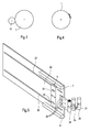
- a winding machine includes, inter alia, as a Anpresstrommel or Carrying drum designated winding roller 17 (Fig. 1).
- a material web will either from a calender, not shown here, a calender, a Final group of a finishing machine or a dryer section of a Paper or board machine led out, then wraps usually a Leit- or Spreader roller and runs on the lateral surface of the winding roller 17, wraps around this at a certain angle to one between the winding roller and a winding roll 1 existing nip and finally on the winding roll. 1 wound.
- the winding roll 1 (Fig. 2) is wound with a roll of a fibrous web and is located in a winding device or elsewhere in a machine for producing or refining a fibrous web.
- the winding roll 1 is rotatable with its shaft 2 in a bearing bracket with side walls 3, 4 stored.
- the winding roller 1 is preferably also driven (Center Drive).
- a cutting device 5 On the underside of the winding roll is a cutting device 5 between terminal strips 6, 7 arranged.
- Two conveyor rollers 8, 9 serve to transport a Strip 10 from one layer or from several layers of the coil.
- the terminal strips 6, 7 are preferably integrated in a traverse of the winding unit, which also receives a Beerabquetsch sensible.
- Such Beerabquetsch is known for example from EP 0 788 991 B1 or EP 0 741 373 B1.
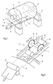
- the terminal strips 6, 7 are from the bottom of the winding roll 1 fixed pressed against the outer layer of the roll. These are on the bottom of the Terminal strips 6, 7 provided pneumatic or hydraulic cylinder, which required Apply pressure.
- the winding is fixed so that in the direction of the longitudinal axis movable cutting device 5 in shape a roller 11 with two lateral strips 12, 13 with cutting teeth between the terminal strips 6, 7 is movable.
- the roller 11 is either by a compressed air or hydraulically driven motor moves or through an electric motor. According to the length of the teeth on the strips 12, 13 and in accordance with the contact pressure of the terminal strips 6, 7 against the winding becomes a certain number of layers of the coil strip-shaped from the fibrous web cut out.
- the roller 11 can be also use cutting wedges, similar to the roller 11 along the terminal strips 6, 7 are performed.
- the Separate at least one water jet or at least one laser beam used under a protective atmosphere.
- rollers 14, 15 are provided, which are in close proximity to the Cutting roller 11 are moved, preferably at a fixed distance to her.
- the rollers 14, 15 press as well as the terminal strips 6, 7 from below against the Winding and thereby contribute to the strip with one or more Layers of the wrap is cut out clean.
- the rollers 14, 15 have either a cylindrical shell or are in the Center concave to strengthen on their faces, that is in close proximity to the cutting surfaces of the cutting bars 12, 13, exert pressure. Additionally or alternatively, the rollers 14, 15 have the function already cut out Press layers against the winding drum 1 and fix it.
- suction hose is preferably Also attached to the bottom of such a suction hose to a central positioning of the strip 10 between the two suction hoses to reach.
- 10 are also behind in the conveying direction of the strip arranged the conveyor rollers 8, 9 more suction devices.
- the strip 10 is transported either via a conveyor belt to a sampling station or wound up on a roll. This will then be in the safe, for that Operators accessible area brought. Alternatively can be by means of of the suction hose and the strip itself to the sampling station.
- the after the cutting out of the strip 10 remaining residual rind of the roll is automatically on the rotary drive of the winding roll 1 and a Disposed of discharge shaft.
- a roll on the winding roll 1 is by means of a device for Sampling a strip taken from the top layer of the roll. It will the position of a cutting device 5 (FIG. 4) attached to the device preferably chosen so that the strip above the through the longitudinal axis of the Wickels ongoing horizontal plane is (Fig. 5).
- the device comprises a cutting device 5 with two at a distance from each other arranged knife blades 18, 19, which slit the upper layer of the coil or disconnect.
- the cutting device 5 is motorized in guides 20, 21 or moved on guide rails.
- the cutting device comprises upper and lower side arranged terminal strips 6, 7, which are pressed firmly against the outer layer of the roll.
- terminal strips 6, 7, which are pressed firmly against the outer layer of the roll are provided which provide the required pressure muster.
- the winding is fixed so that the direction the longitudinal axis aligned cutting device is movable.
- a case of the knife blades 18, 19 cut off strip is from a essentially plate-shaped structure in the form of a Plexiglas plate 22 electrostatically tightened and about Abziehrollen 23, such as rubber rollers and wound up and then preferably glued at the end.
- the Abziehrollen 23 can be acted upon by a pressing or applying device be. The gluing process is similar to that in a labeling machine from. Subsequently, the roll-shaped wound strip in transport containers 24, 25, 26 transported away.
- This purpose is served by a preferably mounted on the driver's side of the machine Transport device 27, in particular in the manner of a pneumatic tube cartridge.
- the onward transport is automatically realized.
- the transport device 27 may be known Represent holders for the cartridges, for example in the form of a revolver magazine. Such Revolver magazines are especially for the Tool stock used in automatic machining centers.
- the device is preferably in connection with a device for automatic removal of the outer rollover of the roll on the winding roll 1, if the outer rind is to be disposed of.
- a device for automatic removal of the outer rollover of the roll on the winding roll 1, if the outer rind is to be disposed of By a circulating conveyor belt be transported to disposal outer layers of the roll.
- a Arrangement for removing unusable outer layers of the roll is preferably attached to the opposite side of the leader.
- Plexiglas disk 22 is preferably a carried by the cutter 5 felt cloth provided under Sliding friction against the plexiglass disk 22 is pressed to charge them.
Landscapes
- Replacement Of Web Rolls (AREA)
Applications Claiming Priority (4)
| Application Number | Priority Date | Filing Date | Title |
|---|---|---|---|
| DE2003138783 DE10338783A1 (de) | 2003-08-23 | 2003-08-23 | Vorrichtung zum Entfernen eines Streifens eines Wickels von einer Wickeltrommel |
| DE10338783 | 2003-08-23 | ||
| DE10343451 | 2003-09-19 | ||
| DE2003143451 DE10343451A1 (de) | 2003-09-19 | 2003-09-19 | Vorrichtung zum Entfernen von Lagen eines Wickels von einem Wickeltambour |
Publications (2)
| Publication Number | Publication Date |
|---|---|
| EP1510486A2 true EP1510486A2 (fr) | 2005-03-02 |
| EP1510486A3 EP1510486A3 (fr) | 2005-09-21 |
Family
ID=34105484
Family Applications (1)
| Application Number | Title | Priority Date | Filing Date |
|---|---|---|---|
| EP04103888A Withdrawn EP1510486A3 (fr) | 2003-08-23 | 2004-08-12 | Dispositif pour enlever au moins une couche d'un rouleau bobiné |
Country Status (1)
| Country | Link |
|---|---|
| EP (1) | EP1510486A3 (fr) |
Cited By (2)
| Publication number | Priority date | Publication date | Assignee | Title |
|---|---|---|---|---|
| CN108356888A (zh) * | 2018-03-26 | 2018-08-03 | 张家港市欧微自动化研发有限公司 | 一种医疗棉签切水口加工设备 |
| CN113442217A (zh) * | 2021-06-28 | 2021-09-28 | 成都飞机工业(集团)有限责任公司 | 一种热塑性复合材料的切割设备及切割方法 |
Family Cites Families (3)
| Publication number | Priority date | Publication date | Assignee | Title |
|---|---|---|---|---|
| SE444083B (sv) * | 1981-10-13 | 1986-03-17 | Lo Juntec Hb | Apparat for utskerning av remsor |
| SE516016C2 (sv) * | 1995-07-12 | 2001-11-05 | Lorentzen & Wettre Ab | Apparat för att skära ut en provremsa |
| DE19710657A1 (de) * | 1997-03-14 | 1998-09-17 | Focke & Co | Verfahren und Vorrichtung zum Handhaben von Bobinen |
-
2004
- 2004-08-12 EP EP04103888A patent/EP1510486A3/fr not_active Withdrawn
Cited By (2)
| Publication number | Priority date | Publication date | Assignee | Title |
|---|---|---|---|---|
| CN108356888A (zh) * | 2018-03-26 | 2018-08-03 | 张家港市欧微自动化研发有限公司 | 一种医疗棉签切水口加工设备 |
| CN113442217A (zh) * | 2021-06-28 | 2021-09-28 | 成都飞机工业(集团)有限责任公司 | 一种热塑性复合材料的切割设备及切割方法 |
Also Published As
| Publication number | Publication date |
|---|---|
| EP1510486A3 (fr) | 2005-09-21 |
Similar Documents
| Publication | Publication Date | Title |
|---|---|---|
| DE3346592C2 (de) | Verfahren und Vorrichtung zum Ersetzen einer auslaufenden Wicklung von Streifenmaterial durch eine neue Wicklung | |
| EP0442038A2 (fr) | Méthode et dispositif pour le remplacement automatique d'une bobine pleine par un nouveau noyau d'enroulement | |
| EP1185398B1 (fr) | Unite d'acheminement de feuille intercalaire pour une machine a decouper un produit | |
| EP0462157B1 (fr) | Dispositif pour relier des bandes de materiau | |
| DE2724955A1 (de) | Rollenwickelmaschine zur bildung von einzelwickeln | |
| DE2708644A1 (de) | Verfahren und vorrichtung zum verspleissen von blatt- oder bahnfoermigem material | |
| DE3249055T1 (de) | Vorrichtung zum Ausschneiden von Streifen aus flexiblen Bahnen | |
| DE102013104978B4 (de) | Maschine zum Aufwickeln von bahnförmigen Materialien | |
| DE3538889C2 (de) | Streifenschneidanlage | |
| DE3916740C2 (de) | Textilmaschine mit verstellbarer Glättwalzenanordnung | |
| EP0379861B1 (fr) | Dispositif pour joindre des feuilles | |
| DE4439605C1 (de) | Verfahren und Vorrichtung zum Sägen von Papierrollen | |
| EP0997415A1 (fr) | Enrouleuse | |
| EP1510486A2 (fr) | Dispositif pour enlever au moins une couche d'un rouleau bobiné | |
| EP0327725B1 (fr) | Bobineuse avec cylindres porteurs pour enrouler une feuille continue, notamment une feuille continue en papier ou carton, aux mandrins | |
| DE3230544C2 (de) | Vorrichtung zur Beseitigung von Lufteinschlüssen zwischen einer Kalanderwalzenoberfläche und einer kalandrierten Gummi- oder Kunststoffplatte | |
| DE4415316A1 (de) | Rollenwickelmaschine | |
| DE68909791T2 (de) | Vorrichtung zum verbinden von zwei materialbahnen. | |
| DE10338783A1 (de) | Vorrichtung zum Entfernen eines Streifens eines Wickels von einer Wickeltrommel | |
| DE20012140U1 (de) | Vorrichtung zum Herausziehen und Reinigen von Schaberklingen | |
| DE202013102342U1 (de) | Spleißeinrichtung zum Spleißen von Cordmaterial | |
| DE10343451A1 (de) | Vorrichtung zum Entfernen von Lagen eines Wickels von einem Wickeltambour | |
| EP1518808A1 (fr) | Dispositif et procédé pour l'extraction d'une bande d'un rouleau de matière fibreuse | |
| EP0733569B1 (fr) | Dispositif d'enroulement avec boítier | |
| DE4446766C2 (de) | Streifenschneidmaschine zum Herstellen von Teppichsockelleisten |
Legal Events
| Date | Code | Title | Description |
|---|---|---|---|
| PUAI | Public reference made under article 153(3) epc to a published international application that has entered the european phase |
Free format text: ORIGINAL CODE: 0009012 |
|
| AK | Designated contracting states |
Kind code of ref document: A2 Designated state(s): AT BE BG CH CY CZ DE DK EE ES FI FR GB GR HU IE IT LI LU MC NL PL PT RO SE SI SK TR |
|
| AX | Request for extension of the european patent |
Extension state: AL HR LT LV MK |
|
| PUAL | Search report despatched |
Free format text: ORIGINAL CODE: 0009013 |
|
| AK | Designated contracting states |
Kind code of ref document: A3 Designated state(s): AT BE BG CH CY CZ DE DK EE ES FI FR GB GR HU IE IT LI LU MC NL PL PT RO SE SI SK TR |
|
| AX | Request for extension of the european patent |
Extension state: AL HR LT LV MK |
|
| 17P | Request for examination filed |
Effective date: 20060321 |
|
| AKX | Designation fees paid |
Designated state(s): AT BE BG CH CY CZ DE DK EE ES FI FR GB GR HU IE IT LI LU MC NL PL PT RO SE SI SK TR |
|
| RAP1 | Party data changed (applicant data changed or rights of an application transferred) |
Owner name: VOITH PATENT GMBH |
|
| STAA | Information on the status of an ep patent application or granted ep patent |
Free format text: STATUS: THE APPLICATION IS DEEMED TO BE WITHDRAWN |
|
| 18D | Application deemed to be withdrawn |
Effective date: 20090505 |