EP1510401A2 - Fahrzeugaussenleuchte - Google Patents
Fahrzeugaussenleuchte Download PDFInfo
- Publication number
- EP1510401A2 EP1510401A2 EP04019666A EP04019666A EP1510401A2 EP 1510401 A2 EP1510401 A2 EP 1510401A2 EP 04019666 A EP04019666 A EP 04019666A EP 04019666 A EP04019666 A EP 04019666A EP 1510401 A2 EP1510401 A2 EP 1510401A2
- Authority
- EP
- European Patent Office
- Prior art keywords
- light
- lens
- region
- holder
- outdoor
- Prior art date
- Legal status (The legal status is an assumption and is not a legal conclusion. Google has not performed a legal analysis and makes no representation as to the accuracy of the status listed.)
- Withdrawn
Links
Images
Classifications
-
- B—PERFORMING OPERATIONS; TRANSPORTING
- B60—VEHICLES IN GENERAL
- B60Q—ARRANGEMENT OF SIGNALLING OR LIGHTING DEVICES, THE MOUNTING OR SUPPORTING THEREOF OR CIRCUITS THEREFOR, FOR VEHICLES IN GENERAL
- B60Q1/00—Arrangement of optical signalling or lighting devices, the mounting or supporting thereof or circuits therefor
- B60Q1/26—Arrangement of optical signalling or lighting devices, the mounting or supporting thereof or circuits therefor the devices being primarily intended to indicate the vehicle, or parts thereof, or to give signals, to other traffic
- B60Q1/32—Arrangement of optical signalling or lighting devices, the mounting or supporting thereof or circuits therefor the devices being primarily intended to indicate the vehicle, or parts thereof, or to give signals, to other traffic for indicating vehicle sides, e.g. clearance lights
-
- B—PERFORMING OPERATIONS; TRANSPORTING
- B60—VEHICLES IN GENERAL
- B60Q—ARRANGEMENT OF SIGNALLING OR LIGHTING DEVICES, THE MOUNTING OR SUPPORTING THEREOF OR CIRCUITS THEREFOR, FOR VEHICLES IN GENERAL
- B60Q1/00—Arrangement of optical signalling or lighting devices, the mounting or supporting thereof or circuits therefor
- B60Q1/26—Arrangement of optical signalling or lighting devices, the mounting or supporting thereof or circuits therefor the devices being primarily intended to indicate the vehicle, or parts thereof, or to give signals, to other traffic
- B60Q1/2657—Arrangement of optical signalling or lighting devices, the mounting or supporting thereof or circuits therefor the devices being primarily intended to indicate the vehicle, or parts thereof, or to give signals, to other traffic mounted on a shaft, e.g. telescopic
Definitions
- the invention relates to an outdoor lamp with a holder for mounting on a Vehicle, a housing arranged on the lamp housing, the at least one inner and an at least outer lens has, wherein the inner lens a limited interior chamber, in which at least one light source is arranged, wherein between the inner lens and the outer lens an outer chamber is formed by at least two, by a weld with each other connected wall sections is limited.
- Such, designed as a marker lamp outdoor light is off DE 297 21 536 U1. It has a dome-shaped or domed inner lens on, which bounds a closed inner chamber, in the bulbs as an incandescent lamp is arranged. On the inner lens left and right are different outer light disks welded in such a way that between these and the inner Lens a waterproof outer chamber is formed. Through the two chambers are the lamp and its associated electrical connections from environmental influences and in particular protected against corrosion. The regulations of a marker lamp Accordingly, the two outer lenses have different Colors on. The individual light disks that make up the outdoor lamp is, but still require some manufacturing and assembly costs, as the different colored parts first produced in separate injection molding and then be connected by welds waterproof and correct position together have to.
- This object is achieved in that between the inner lens and the outer lens, an optical filter disc is inserted into the outer chamber.
- this makes it possible for the inner and outer lens existing luminaire housing made of only two parts, which after the Inserting the filter disc in the outer chamber to form a multi-color disc be welded together watertight.
- the outdoor light is therefore inexpensive produced.
- a first light disc area of the inner Lens and a first lens area of the outer lens arranged, wherein, starting from the light source in a second direction behind a second Lens area of the inner of the lens and a second lens area the outer lens are arranged, and wherein the filter disc to form a Multicolor lens is arranged only between the first light disk areas.
- the outdoor light then radiates differently in different directions colored light off. For example, with an outline light, the lens may turn white or colorless and the filter disc be red, so that the outdoor light after white at the front and red light at the back.
- the outdoor light can then be for both the left and the right Vehicle side are used, with the lamp housing on the right side of the vehicle is rotated by 180 ° relative to the left side of the vehicle.
- the lighting means in a third direction one after the other a third light disc area of the inner lens and a third one Lens area of the outer lens are arranged when the first and second lens area of the outer lens integral with the inner lens are connected when the third lens area of the outer lens an access opening for the filter disc covers and with the first and second Lens area of the outer lens is welded.
- the third one Lens area of the outer lens preferably has a different color than that first and second lens area of this lens, the last two said lens areas preferably white or colorless and the third lens area the outer lens are formed yellow.
- the inner lens and / or the outer lens at least one optic whose focal point at the Abstrahlstelle of the light source is arranged, the optics preferably such is formed, that the opening angle of the light beam emerging from the optics at least 80 °.
- the outdoor light can then be used as a marker light in all Mounted mounting positions from 0 ° to 360 ° on the vehicle, whereby the legal Regulations for the emission characteristics are met.
- the luminaire housing a collar-shaped, peripheral edge region having an access opening to the inner chamber bounded when at the Holder is provided an appropriate to the edge region annular groove when the holder at least in the region of the annular groove is made of an elastic material, and when the collar-shaped edge region engages in the annular groove such that the elastic Material seals the access opening.
- the elastic material of the holder is preferably rubber. The lamp located in the inner chamber and this associated electrical parts are then sealed well against moisture. Yet can the luminaire housing by pulling out of the collar-shaped edge region the annular groove can be easily separated from the holder, so that the light source and the inner chamber are then easily accessible.
- the holder has a Recording on, in which the lamp housing is used so that at least one Part of the bracket in the use position the lamp housing form-fitting engages behind, wherein the holder at least in the region of the receptacle of a material consists, which is elastically deformable such that the lamp housing of the recording is separable.
- the holder is designed as a holding arm, which at its one End of the receptacle for the luminaire housing and at its opposite another end portion a mounting flange for connecting the support arm with the Vehicle has.
- the outdoor light can then easily on one side Trucks are mounted.
- the support arm of a channel penetrated from the mounting flange to electrical connections for the Luminous means leads, wherein in the channel electrical lines for the power supply of the Illuminant are arranged. The electrical wires are then in the channel Spray and backwater protected.
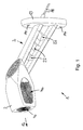
- a designated in Fig. 1 and 2 as a whole with 1 outdoor lamp has a holder. 2 for mounting on a vehicle.
- On the holder 2 is an approximately cuboid Luminaire housing arranged, the inner lens 3 and an outer lens 4 has.
- the inner lens 3 is approximately bell-shaped or dome-shaped and defines a closed inner chamber 5, in which an electric lighting means 6 is arranged.
- the outer lens 4 and the inner lens 3 each have a plurality of lens areas on.
- a first lens area 3a of the inner lens 3 and a first lens area 4a of the outer lens 4 are radially to Abstrahlstelle 7 of the bulb 6 arranged one behind the other and for one for a Front limiting light function provided.
- In use position of the outdoor light 1 have the light disk areas 3a, 4a approximately in the forward direction of travel of the vehicle.
- a second light disk region 3b of the inner lens 3 and a second lens region 4b of the outer lens 4 are radially to the emission of the lamp 6 arranged one behind the other and for a rear limiting light function educated.
- the light disk areas 3b, 4b approximately in the direction of the forward direction of the vehicle opposite direction.
- a third lens area 3c of the inner lens 3 and a third area of the lens 4c of the outer lens 4 are radially to the emission of the lamp 6 arranged one behind the other and designed for a sobegrenzungslichtfunktion.
- the outdoor lamp 1 In Use position of the outdoor lamp 1 are the light disk areas 3c, 4c on the Vehicle side facing away from the bulb 6 and have in an approximately 90 ° to the forward direction extending horizontal direction.
- the inner lens with the lens areas 3a, 3b, 3c and the first and second light disc region 4a, 4b of the outer lens are integral with each other connected. They are part of a first luminaire housing part, as a plastic injection molded part made of a crystal-clear material.
- the third lens area 4c of the outer lens consists of a translucent yellow plastic and forms a second light housing part.
- an outer chamber 8 formed, in which a red optical filter disk 9 is inserted, which is continuous over the first light disc region 3b of the inner lens 3 and the first lens area 4b of the outer lens 4 extends.
- the outer chamber 8 in height of the light emitting point of the bulb. 6 has two approximately U-shaped chamber areas, by partition walls 10 from each other are spaced, which the inner lens 3 on both sides of the bulb 6 approximately connect radially to the emission point 7 of the bulb 6 with the outer lens 4. In one of the U-shaped chamber regions, the arcuately curved filter disk 9 held positively.
- the two are the different colors having lamp housing parts and the filter disk 9 made.
- the first, the inner lens 3 and the first and second lens area 4a, 4b of outer lens 4 having lamp housing part has at the point at the later the one formed by the third light disk portion 4c of the outer lens 4 second housing part is arranged, an access opening to the outer chamber 8.
- This access opening through the filter disk 9 is introduced into the outer chamber 8.
- the second housing part 4 c is positioned at the access opening and by means of a single, annular around the outer chamber 8 circumferential weld welded watertight to the edge of the access opening, preferably by ultrasonic welding.
- the outer chamber 8 then forms a sealed chamber in which the Filter disc 9 is included.
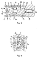
- Fig. 3 and 4 it can be seen that the filter disk 9 only between the first lens area 3a of the inner lens 3 and the first lens area 4a the outer lens 4 is arranged, so that the outdoor lamp 1 against the Forward direction of the vehicle despite the crystal clear design of these lens areas 3a, 4a emits red light.
- the inner lens 3 and the second lens area 4b of the outer Lens 4 is not arranged filter disc, which is why the outdoor lamp 1 in Forward direction white light emits.
- Also between the third lens area 3c of the inner lens 3 and the third lens 4c of the outer Lens 4 is no filter disc provided, so that the outdoor light 1 across the Direction of travel because of the yellow color of the lens area 4c yellow light radiates.
- the three light-disk regions 4a, 4b, 4c of the outer lens 4 are in each case their outer side facing away from the bulb 6 on a Fresnel optics.
- the Focal points of these optics are in each case at the emission point of the luminous means 6 arranged.
- the Fresnel optics are designed such that the opening angle of from each emerging light beam is at least 80 °.
- the outdoor lamp 1 therefore meets the legal requirements for any cultivation position between 0 ° and 360 ° Requirements for the emission characteristics of a marker lamp.
- the lamp housing at its from the lens area 4c remote end has a collar-shaped edge portion 10, the order the inner chamber 5 rotates and defines an access opening to the inner chamber 5.
- a matching to the edge portion 10 annular groove is provided in the the edge region 10 engages.
- the holder consists of a elastic rubber material, both against the inner circumference and against the Outer circumference of the edge portion 10 seals radially to the bulb 6,
- Figure 3 is recognizable that the side walls of the annular groove with a wave-shaped profiling have a plurality of successively arranged sealing lips. This results in a particularly good sealing of the inner chamber 5 against moisture.
- the holder 2 has a receptacle into which the Luminaire housing is used such that portions of the elastic rubber material the holder 2 engage behind the lamp housing form fit and thus the Fix the luminaire housing in the receptacle.
- the picture shows at the front and Rear side and on the side facing away from the vehicle in use position side the outdoor light 1 openings for the three light disk areas 4a, 4b, 4c of the outer Lens 4 on.
- the elasticity of the rubber material is chosen so that the luminaire housing from the recording of the holder in the direction of arrow 12 is pulled out.
- the shock- and shock-absorbing rubber material surrounds all three lens areas 4a, 4b, 4c of the outer lens 4 and the top, bottom and back of the luminaire housing.
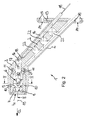
- Fig. 4 it can be seen that the light disks 3, 4 having Luminaire housing is designed so symmetrical that it is in two by 180 ° to its longitudinal central axis 18 mutually rotated layers in the receptacle of the holder. 2 can be used.
- the outdoor light 1 can therefore both on the left and on the right side of the vehicle to be complained.
- the holder 2 is designed as a holding arm, which at its an end portion of the receptacle for the luminaire housing and at its opposite another end portion a mounting flange 13 for connection to the Body of the vehicle has. At the mounting flange 13 are perforations 14th intended for the passage of screws. In the region of the mounting flange 13 The holder 2 has a carrier plate 15 which is encased in the rubber material or is overmoulded. The main extension direction of the support arm extends approximately below an angle of 45 ° to the plane of the mounting flange 13. The longitudinal axis of Luminaire housing is approximately at right angles to the plane of the mounting flange thirteenth arranged.
- the holder 2 is penetrated by a channel 16 which extends from the mounting flange 13 leads to electrical connections 17 for the lamp 6.
- electrical lines 18 for the power supply of the bulb 6 the of the rubber material of the holder 2 are enclosed radially sealing.
- At one Inner wall portion of the channel 16 are to several, in the extension direction of the Lines 18 provided successively arranged sealing lips, which are elastic on a Cladding of the lines 18 abut.
- the electrical connections 17 for the lamp 6 are on a base part 20th arranged, which is releasably connectable to the lighting means 6, for example by means of a Plug, screw or bayonet connection.
- the base part 20 is in one of the inner chamber 5 facing receiving recess of the holder 2 is inserted and has at one of the bulbs 6 spaced outer peripheral portion on a collar 21, the positively in a circumferential on the inner circumference of the receiving recess groove of the Holder 2 engages.
- the support arm of the holder 2 is approximately a double-T-shaped Has cross section and transverse to its the drawing plane in Fig. 2 corresponding Extension plane of several in the extension direction of the support arm from each other spaced holes 22 is penetrated, which the bending stiffness of the support arm in influence a direction transverse to the plane of extension of the support arm direction.
- Be used plastic plug which are not shown in detail in the drawing. The Plastic plugs may optionally with the rubber material of the holder. 2 to be splashed.
Landscapes
- Engineering & Computer Science (AREA)
- Mechanical Engineering (AREA)
- Non-Portable Lighting Devices Or Systems Thereof (AREA)
Abstract
Description
- Fig. 1
- eine dreidimensionale Ansicht einer Außenleuchte,
- Fig. 2
- einen Längsschnitt durch die Außenleuchte,
- Fig. 3
- einen Längsschnitt durch die in Fig. 2 mit III bezeichnete Ebene der Außenleuchte, und
- Fig. 4
- einen Querschnitt durch die in Fig. 2 mit IV bezeichnete Ebene der Außenleuchte.
Claims (10)
- Außenleuchte (1) mit einer Halterung (2) zur Montage an einem Fahrzeug, einem an der Halterung (2) angeordneten Leuchtengehäuse, das mindestens eine innere Lichtscheibe (3) und eine wenigstens äußere Lichtscheibe (4) hat, wobei die innere Lichtscheibe (3) eine geschlossene Innenkammer (5) begrenzt, in der mindestens ein Leuchtmittel (6) angeordnet ist, wobei zwischen der inneren Lichtscheibe (3) und der äußeren Lichtscheibe (4) eine Außenkammer (8) gebildet ist, die durch mindestens zwei, durch eine Schweißnaht miteinander verbundene Wandungsabschnitte begrenzt ist, dadurch gekennzeichnet, dass zwischen der inneren Lichtscheibe (3) und der äußeren Lichtscheibe (4) eine optische Filterscheibe (9) in die Außenkammer eingelegt ist.
- Außenleuchte (1) nach Anspruch 1, dadurch gekennzeichnet, dass ausgehend von dem Leuchtmittel (6) in eine erste Richtung hintereinander ein erster Lichtscheibenbereich (3a) der inneren Lichtscheibe (3) und ein erster Lichtscheibenbereich (4a) der äußeren Lichtscheibe (4) angeordnet sind, dass ausgehend von dem Leuchtmittel (6) in eine zweite Richtung hintereinander ein zweiter Lichtscheibenbereich (3b) der inneren der Lichtscheibe (3) und ein zweiter Lichtscheibenbereich (4b) der äußeren Lichtscheibe (4) angeordnet sind, und dass die Filterscheibe (9) zur Bildung einer Mehrfarbenlichtscheibe nur zwischen den ersten Lichtscheibenbereichen (3a, 4a) angeordnet ist.
- Außenleuchte (1) nach Anspruch 1 oder 2, dadurch gekennzeichnet, dass die Richtung, in der die ersten Lichtscheibenbereiche (3a, 4a) angeordnet sind, entgegengesetzt zu der Richtung verläuft, in der die zweiten Lichtscheibenbereiche (3b, 4b) angeordnet sind und dass das Leuchtengehäuse vorzugsweise symmetrisch zu einer normal zu diesen Richtungen verlaufenden Ebene ausgebildet ist.
- Außenleuchte (1) nach einem der Ansprüche 1 bis 3, dadurch gekennzeichnet, dass ausgehend von dem Leuchtmittel (6) in eine dritte Richtung hintereinander ein dritter Lichtscheibenbereich (3c) der inneren Lichtscheibe (3) und ein dritter Lichtscheibenbereich (4c) der äußeren Lichtscheibe (4) angeordnet sind, dass der erste und zweite Lichtscheibenbereich (4a, 4b) der äußeren Lichtscheibe. (4) einstückig mit der inneren Lichtscheibe (3) verbunden sind, dass der dritte Lichtscheibenbereich (4c) der äußeren Lichtscheibe (4) eine Zugangsöffnung für die Filterscheibe (9) überdeckt und mit dem ersten und zweiten Lichtscheibenbereich (4a, 4b) der äußeren Lichtscheibe (4) verschweißt ist.
- Außenleuchte (1) nach einem der Ansprüche 1 bis 4, dadurch gekennzeichnet, dass der dritte Lichtscheibenbereich (4c) der äußeren Lichtscheibe (4) eine andere Farbe aufweist als der erste und zweite Lichtscheibenbereich (4a, 4b) dieser Lichtscheibe (4), und dass die beiden zuletzt genannten Lichtscheibenbereiche (4a, 4b) vorzugsweise weiß oder farblos und der dritte Lichtscheibenbereich (4c) der äußeren Lichtscheibe (4) gelb ausgebildet sind.
- Außenleuchte (1) nach einem der Ansprüche 1 bis 5, dadurch gekennzeichnet, dass die innere Lichtscheibe (3) und/oder die äußere Lichtscheibe (4) wenigstens eine Optik aufweist, deren Brennpunkt an der Abstrahlstelle (7) des Leuchtmittels (6) angeordnet ist, und dass die Optik vorzugsweise derart ausgebildet ist, dass der Öffnungswinkel des aus der Optik austretenden Lichtbündels mindestens 80° beträgt.
- Außenleuchte (1) nach einem der Ansprüche 1 bis 7, dadurch gekennzeichnet, dass das Leuchtengehäuse einen kragenförmigen, umlaufenden Randbereich (11) aufweist, der eine Zugangsöffnung zu der Innenkammer (5) umgrenzt, dass an der Halterung (2) eine zu dem Randbereich (11) passende Ringnut vorgesehen ist, dass die Halterung (2) zumindest im Bereich der Ringnut aus einem elastischen Werkstoff besteht ist, und dass der kragenförmige Randbereich (11) derart in die Ringnut eingreift, dass der elastische Werkstoff die Zugangsöffnung abdichtet.
- Außenleuchte (1) nach einem der Ansprüche 1 bis 7, dadurch gekennzeichnet, dass die Halterung (2) eine Aufnahme aufweist, in die das Leuchtengehäuse derart einsetzbar ist, dass mindestens ein Teilbereich der Halterung (2) in Gebrauchsstellung das Leuchtengehäuse formschlüssig hintergreift, dass die Halterung (2) zumindest im Bereich der Aufnahme aus einem Werkstoff besteht, der derart elastisch verformbar ist, dass das Leuchtengehäuse von der Aufnahme trennbar ist.
- Außenleuchte (1) nach einem der Ansprüche 1 bis 8, dadurch gekennzeichnet, dass die Halterung (2) als Haltearm ausgebildet ist, der an seinem einen Endbereich die Aufnahme für das Leuchtengehäuse und an seinem gegenüberliegenden anderen Endbereich einen Befestigungsflansch (13) zum Verbinden des Haltearms mit dem Fahrzeug aufweist.
- Außenleuchte (1) nach einem der Ansprüche 1 bis 9, dadurch gekennzeichnet, dass der Haltearm von einem Kanal (16) durchsetzt ist, der von dem Befestigungsflansch (13) zu elektrischen Anschlüssen (17) für das Leuchtmittel führt, und dass in dem Kanal (16) elektrische Leitungen (18) für die Stromversorgung des Leuchtmittels (6) angeordnet sind.
Applications Claiming Priority (2)
| Application Number | Priority Date | Filing Date | Title |
|---|---|---|---|
| DE10339878 | 2003-08-29 | ||
| DE2003139878 DE10339878A1 (de) | 2003-08-29 | 2003-08-29 | Fahrzeugaußenleuchte |
Publications (2)
| Publication Number | Publication Date |
|---|---|
| EP1510401A2 true EP1510401A2 (de) | 2005-03-02 |
| EP1510401A3 EP1510401A3 (de) | 2006-04-19 |
Family
ID=34089259
Family Applications (1)
| Application Number | Title | Priority Date | Filing Date |
|---|---|---|---|
| EP04019666A Withdrawn EP1510401A3 (de) | 2003-08-29 | 2004-08-19 | Fahrzeugaussenleuchte |
Country Status (2)
| Country | Link |
|---|---|
| EP (1) | EP1510401A3 (de) |
| DE (1) | DE10339878A1 (de) |
Cited By (3)
| Publication number | Priority date | Publication date | Assignee | Title |
|---|---|---|---|---|
| EP1661759A1 (de) * | 2004-11-27 | 2006-05-31 | Hella KG Hueck & Co. | Leuchte für Nutzfahrzeuge |
| WO2013102539A1 (de) * | 2012-01-03 | 2013-07-11 | Continental Reifen Deutschland Gmbh | Vorrichtung zum anzeigen eines reifendruck-zustandes für fahrzeugreifen eines lastwagen-anhängers |
| EP4015310A1 (de) * | 2020-12-17 | 2022-06-22 | JN QualityExpert Oy | Aufsetzbare seitenleuchte für einen an einem kraftfahrzeug ankuppelbaren anhänger oder eine gezogene vorrichtung |
Families Citing this family (1)
| Publication number | Priority date | Publication date | Assignee | Title |
|---|---|---|---|---|
| DE102015106242B4 (de) * | 2015-04-23 | 2020-09-17 | Proplast Fahrzeugbeleuchtung Gmbh | Begrenzungsleuchte für Fahrzeuge |
Citations (1)
| Publication number | Priority date | Publication date | Assignee | Title |
|---|---|---|---|---|
| DE29721536U1 (de) | 1997-12-05 | 1999-04-08 | Kunststofftechnik Jedermann GmbH, 56291 Hausbay | Außenbeleuchtungsvorrichtung zur Montage an einem Fahrzeug |
Family Cites Families (7)
| Publication number | Priority date | Publication date | Assignee | Title |
|---|---|---|---|---|
| US3225189A (en) * | 1962-10-15 | 1965-12-21 | Key Machine Tool Corp | Lamp mount |
| US4231082A (en) * | 1978-02-10 | 1980-10-28 | Nartron Corporation | Lamp assembly light shield and retaining means |
| DE3040812A1 (de) * | 1980-10-30 | 1982-05-27 | Robert Bosch Gmbh, 7000 Stuttgart | Ein farblichtbuendel erzeugender scheinwerfer fuer fahrzeuge, insbesondere kraftfahrzeuge |
| IT214517Z2 (it) * | 1988-02-29 | 1990-05-09 | Sirena Spa | Segnalatore luminoso di pericolo in particolare per veicoli lenti |
| DE19854303A1 (de) * | 1998-11-25 | 2000-06-29 | Hella Kg Hueck & Co | Fahrzeugleuchte |
| DE10046362A1 (de) * | 2000-09-20 | 2002-03-28 | Hella Kg Hueck & Co | Leuchte für Nutzfahrzeuge |
| DE20111537U1 (de) * | 2001-07-13 | 2002-11-21 | Kunststofftechnik Jedermann GmbH, 56291 Hausbay | Fahrzeugleuchtvorrichtung |
-
2003
- 2003-08-29 DE DE2003139878 patent/DE10339878A1/de not_active Withdrawn
-
2004
- 2004-08-19 EP EP04019666A patent/EP1510401A3/de not_active Withdrawn
Patent Citations (1)
| Publication number | Priority date | Publication date | Assignee | Title |
|---|---|---|---|---|
| DE29721536U1 (de) | 1997-12-05 | 1999-04-08 | Kunststofftechnik Jedermann GmbH, 56291 Hausbay | Außenbeleuchtungsvorrichtung zur Montage an einem Fahrzeug |
Cited By (4)
| Publication number | Priority date | Publication date | Assignee | Title |
|---|---|---|---|---|
| EP1661759A1 (de) * | 2004-11-27 | 2006-05-31 | Hella KG Hueck & Co. | Leuchte für Nutzfahrzeuge |
| WO2013102539A1 (de) * | 2012-01-03 | 2013-07-11 | Continental Reifen Deutschland Gmbh | Vorrichtung zum anzeigen eines reifendruck-zustandes für fahrzeugreifen eines lastwagen-anhängers |
| US9375983B2 (en) | 2012-01-03 | 2016-06-28 | Continental Reifen Deutschland Gmbh | Apparatus for displaying a tire pressure state for vehicle tires of a truck trailer |
| EP4015310A1 (de) * | 2020-12-17 | 2022-06-22 | JN QualityExpert Oy | Aufsetzbare seitenleuchte für einen an einem kraftfahrzeug ankuppelbaren anhänger oder eine gezogene vorrichtung |
Also Published As
| Publication number | Publication date |
|---|---|
| DE10339878A1 (de) | 2005-06-16 |
| EP1510401A3 (de) | 2006-04-19 |
Similar Documents
| Publication | Publication Date | Title |
|---|---|---|
| EP3117141B1 (de) | Kraftfahrzeug und kraftfahrzeugscheinwerfer mit vorsatzgehäuse | |
| DE3438154C2 (de) | Rückleuchte für Kraftfahrzeuge | |
| EP1120312B1 (de) | Aussenrückblickspiegel für Fahrzeuge, vorzugsweise für Kraftfahrzeuge | |
| EP3825601B1 (de) | Lichtelement für ein kraftfahrzeug und kraftfahrzeug | |
| EP1598237A1 (de) | Aussenrückblickspiegel für Fahrzeuge, insbesondere Kraftfahrzeuge | |
| EP2179215A1 (de) | Fahrzeugleuchtvorrichtung mit einem zusatzreflektor zum seitlichen umlenken eines lichtteils einer lichtquelle | |
| DE10131686A1 (de) | Taschenlampe | |
| EP2783155A2 (de) | Beleuchtungsvorrichtung für ein kraftfahrzeug | |
| DE102019112685A1 (de) | Leuchte mit geschützt gelagerten Leuchtmitteln | |
| DE2201698A1 (de) | Dekorative Beleuchtungsvorrichtung | |
| DE102007033706B4 (de) | Fahrzeugleuchtvorrichtung mit einer dreidimensionalen mehrfarbigen Zwischenlichtscheibe | |
| DE102004018695A1 (de) | Außenrückblickspiegel für Fahrzeuge, vorzugsweise Kraftfahrzeuge | |
| DE102004053643A1 (de) | Fahrzeugleuchtenanordnung | |
| EP1510401A2 (de) | Fahrzeugaussenleuchte | |
| EP2014973A2 (de) | Leuchte | |
| DE20110813U1 (de) | Taschenlampe | |
| DE102019112687A1 (de) | Wannenförmiges Leuchtengehäuse | |
| DE202008017583U1 (de) | Stellrad | |
| DE19541509A1 (de) | Scheinwerfer-Leuchten-Einheit für Fahrzeuge | |
| DE102012007999A1 (de) | Wasserbecken mit beleuchteten Randsteinen | |
| DE20314664U1 (de) | Fahrzeugleuchte | |
| DE10232894A1 (de) | Leuchte mit mindestens einer Leuchtdiode als Leuchtmittel | |
| DE3101398A1 (de) | Mehrkammerleuchte fuer fahrzeuge | |
| DE20111537U1 (de) | Fahrzeugleuchtvorrichtung | |
| DE102018215988A1 (de) | Lichtmodul, insbesondere zur Verwendung in einer Beleuchtungsvorrichtung für ein Kraftfahrzeug |
Legal Events
| Date | Code | Title | Description |
|---|---|---|---|
| PUAI | Public reference made under article 153(3) epc to a published international application that has entered the european phase |
Free format text: ORIGINAL CODE: 0009012 |
|
| AK | Designated contracting states |
Kind code of ref document: A2 Designated state(s): AT BE BG CH CY CZ DE DK EE ES FI FR GB GR HU IE IT LI LU MC NL PL PT RO SE SI SK TR |
|
| AX | Request for extension of the european patent |
Extension state: AL HR LT LV MK |
|
| PUAL | Search report despatched |
Free format text: ORIGINAL CODE: 0009013 |
|
| AK | Designated contracting states |
Kind code of ref document: A3 Designated state(s): AT BE BG CH CY CZ DE DK EE ES FI FR GB GR HU IE IT LI LU MC NL PL PT RO SE SI SK TR |
|
| AX | Request for extension of the european patent |
Extension state: AL HR LT LV MK |
|
| 17P | Request for examination filed |
Effective date: 20061011 |
|
| AKX | Designation fees paid |
Designated state(s): AT DE ES FR IT |
|
| 17Q | First examination report despatched |
Effective date: 20061208 |
|
| STAA | Information on the status of an ep patent application or granted ep patent |
Free format text: STATUS: THE APPLICATION IS DEEMED TO BE WITHDRAWN |
|
| 18D | Application deemed to be withdrawn |
Effective date: 20070419 |