EP1510372B1 - Dispositif d'attelage auxiliaire - Google Patents
Dispositif d'attelage auxiliaire Download PDFInfo
- Publication number
- EP1510372B1 EP1510372B1 EP20040020075 EP04020075A EP1510372B1 EP 1510372 B1 EP1510372 B1 EP 1510372B1 EP 20040020075 EP20040020075 EP 20040020075 EP 04020075 A EP04020075 A EP 04020075A EP 1510372 B1 EP1510372 B1 EP 1510372B1
- Authority
- EP
- European Patent Office
- Prior art keywords
- ball
- coupling device
- auxiliary coupling
- base body
- impact protection
- Prior art date
- Legal status (The legal status is an assumption and is not a legal conclusion. Google has not performed a legal analysis and makes no representation as to the accuracy of the status listed.)
- Expired - Lifetime
Links
Images

Classifications
-
- B—PERFORMING OPERATIONS; TRANSPORTING
- B60—VEHICLES IN GENERAL
- B60D—VEHICLE CONNECTIONS
- B60D1/00—Traction couplings; Hitches; Draw-gear; Towing devices
- B60D1/58—Auxiliary devices
- B60D1/60—Covers, caps or guards, e.g. comprising anti-theft devices
- B60D1/605—Protection caps
-
- B—PERFORMING OPERATIONS; TRANSPORTING
- B60—VEHICLES IN GENERAL
- B60D—VEHICLE CONNECTIONS
- B60D1/00—Traction couplings; Hitches; Draw-gear; Towing devices
- B60D1/01—Traction couplings or hitches characterised by their type
- B60D1/06—Ball-and-socket hitches
-
- B—PERFORMING OPERATIONS; TRANSPORTING
- B60—VEHICLES IN GENERAL
- B60D—VEHICLE CONNECTIONS
- B60D1/00—Traction couplings; Hitches; Draw-gear; Towing devices
- B60D1/24—Traction couplings; Hitches; Draw-gear; Towing devices characterised by arrangements for particular functions
- B60D1/36—Traction couplings; Hitches; Draw-gear; Towing devices characterised by arrangements for particular functions for facilitating connection, e.g. hitch catchers
-
- B—PERFORMING OPERATIONS; TRANSPORTING
- B60—VEHICLES IN GENERAL
- B60D—VEHICLE CONNECTIONS
- B60D1/00—Traction couplings; Hitches; Draw-gear; Towing devices
- B60D1/58—Auxiliary devices
- B60D1/60—Covers, caps or guards, e.g. comprising anti-theft devices
Definitions
- the present invention relates to a coupling auxiliary device for trailers, in particular caravans, wherein the coupling auxiliary device has at least one display and positioning device for displaying the position of a trailer hitch of the trailer relative to a towing vehicle.
- a pointing device for indicating the distance between a father piece and a nut piece of a trailer hitch.
- a stand device with a slidably mounted mandrel is arranged on the nut piece.
- the stand device tilts and thus gives an indication of the distance between the coupling and towing vehicle.
- a disadvantage of the prior art Ankupplungssvortechnischen is that they can not prevent accidental collision between the towing vehicle and the trailer so as to cause damage to the towing vehicle or the trailer and in particular the Ankupplungssvortechnisch.
- rams or baffles are used. These usually consist of an elastic material and are arranged on or in front of the ball socket of a coupling claw of the trailer. Examples are in the US-A-5 725 232 . US 4012056 of the DE 33 41 705 A1 , of the DE 39 15 944 A1 or the DE 200 14 237 U1 disclosed.
- a disadvantage of these devices, however, is that even these lack of orientation aids unwanted collision between the towing vehicle and the trailer can not prevent such that it comes to damage the towing vehicle or the trailer and in particular the Ankupplungssvorraum.
- a coupling auxiliary device comprises at least one display and positioning device for indicating the position of a trailer hitch of the trailer relative to a towing vehicle and consists of a base body with a ball for engagement and for releasable attachment to a ball socket of a coupling claw of the trailer and a body at least partially In the direction of the towing vehicle surrounding ram protection of compressible material, wherein the display and positioning device is arranged in the base body or the ram protection. When the ramming protection is touched, the ramming protection is compressed and, as a result, a movement of the display and positioning device takes place.
- the driver of the towing vehicle is informed that the coupling device of the towing vehicle is now in contact with the coupling auxiliary device of the trailer.
- the coupling jaw is also protected against dirt and dust in the area of the ball socket with the coupling auxiliary device attached.
- the coupling auxiliary device can also be used for accident prevention, since the ramming prevents people from injuring themselves on the coupling claw.
- the Rammschutz and the body can be integrally formed. But it is also possible that the crash protection is designed removable from the body.
- the ram protection consists of a volume filled with gas or liquid. This may be, for example, a pneumatic tire or hose.
- the ramming protection or a side wall surrounding the base body or the crash protection and a side wall surrounding the base body at least partially surround the ball in the direction of the towing vehicle.
- they can surround the ball in the direction of the tractor at least partially semicircular.
- the ram protection or a side wall or the ramming protection surrounding the base body and a side wall surrounding the base body to be formed projecting beyond the ball.
- the display and positioning device consists of a rod with at least one display pennant.
- the length of the rod is variable.
- the ball of Ankupplungssvortechnisch a locking mechanism for locking the ball with a ball socket of the coupling claw of the trailer.
- the locking mechanism may advantageously consist of a two-part ball with an upper and a lower half ball and at least one locking pin which is arranged between the ball halves, wherein the upper half of the ball is formed movable relative to the lower half ball and upon movement of the upper half ball the lower half of the locking pin is pushed outwards over the circumference of the ball and presses against the inner circumference of the ball socket of the coupling claw.
- an elastomeric material is arranged, which is pushed at a movement of the upper half of the ball on the lower half of the ball over the circumference of the ball and presses against the inner periphery of the ball socket of the coupling claw.
- the movement of the upper half of the ball relative to the lower half of the ball is usually carried out by means of a guided in a arranged below the ball opening of the body and rotatable hex screw, the hex screw engages with its ball end facing into a clamping bolt and the clamping bolt in an opening of the upper half of the ball is arranged.
- the locking mechanism in a further advantageous embodiment, this is self-lockable.
- the locking mechanism can be closed with a lock which can be inserted into the opening in which the hexagonal screw is guided.
- FIG. 1 shows a schematic and partially sectional view of a coupling auxiliary device 10 according to a first embodiment.
- the coupling auxiliary device 10 in this case has a display and positioning device 12 for displaying the position of a trailer hitch of the trailer relative to a towing vehicle.
- the coupling auxiliary device 10 consists of a base body 14 with a bottom element 16.
- a holding element 40 for supporting and holding a ball 18 is formed on the bottom element 16.
- the ball 18 serves for engagement and releasable attachment with a ball socket 22 of a coupling claw 20 of the trailer.
- the coupling auxiliary device 10 has a ramming protection 24 of compressible material surrounding the base body 16 in the direction of the towing vehicle.
- the ram protection 24 in the illustrated embodiment adjoins a side wall 30 of the main body 14.
- the display and positioning device 12 consists in the illustrated embodiment of a rod 26 (in the figures shown in each case shortened) with a arranged at one end of the rod 26 display pennant 28. Also other optical or acoustic signal generator are conceivable.
- the rod 26 is arranged in the base body 14. But it is also possible that the display and positioning device 12 is connected to the ram guard 24. When the ramming protection 24 is touched, the ramming protection 24 is compressed and a movement of the display and positioning device 12 takes place. This movement indicates to the driver of the towing vehicle that the coupling device of the towing vehicle now bears against the coupling auxiliary device 10 of the trailer.
- the side walls 30 of the main body 14 are reinforced by a plurality of struts 38 pointing radially inwards in the direction of the ball 18.
- the ram guard 24 and / or the base body 14 are usually made of plastic or rubber. In this case, the crash protection 24 and the base body 14 may be integrally formed. In the illustrated embodiment, the ram guard 24 is removable. But it is also possible that the ram protection 24 consists of a filled with gas or liquid volume (not shown).
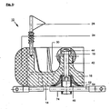
- FIG. 2 shows a plan view of the coupling auxiliary device 10 according to the in FIG. 1 illustrated embodiment. It can be seen that both the base body 14 and the crash protection 24 are semicircular or U-shaped. In this case, the crash protection 24 surrounds the main body 14 almost completely and is arranged along the side wall 30 of the main body 14.
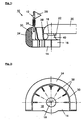
- FIG. 3 shows a side view of the coupling auxiliary device 10 according to the in the Figures 1 and 2 illustrated embodiment.
- the design of the base body 14 with the radially inwardly arranged struts 38 becomes clear.
- the ball 18 is completely formed in its outwardly facing region and is seated on the retaining element 40.
- the ball 18 and the holding member 40 may be formed integrally with the base body 14. But it is also possible that the ball 18 and / or the retaining element 40 glued or screwed to the base body 14.
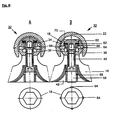
- FIG. 4 shows a sectional view of a coupling auxiliary device 10 according to a second embodiment. It can be seen again that the ramming protection 24 is arranged on the side wall 30 of the main body 14.
- the illustrated coupling auxiliary device 10 has a main body 14 which has an opening 48 in the base element 16, wherein a hexagon socket screw 42 is guided and rotatable within the opening 48 which passes through the bottom element 16 and the retaining element 40.
- the ball 18 facing the end of the hexagon socket screw 42 engages in a self-locking nut 44 which is disposed within an opening 50 in the ball 18.
- a sleeve 46 is arranged, which serves to guide the hexagon socket screw 42 within the ball 18.
- FIG. 5 shows a sectional view of a third embodiment of the coupling auxiliary device 10. It is in addition to the in FIG. 4 described second embodiment of the Ankupplungscousvorraum 10 in this embodiment, in the opening 48 of the bottom member 16 of the base body 14, an additional sleeve 52 is arranged, which is fastened via the hexagon socket screw 42 to the bottom element 16. The sleeve 52 projects out of the bottom element 16 and has an opening 74 for the passage of a safety cable 54 on the protruding section. The safety cable 54 prevents the unwanted removal of the coupling auxiliary device 10 from the trailer.
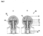
- FIG. 6 shows a sectional view of a fourth embodiment of Ankupplungssvorraum 10.
- the locking mechanism 32 consists of a two-piece ball 18 having an upper and a lower half ball 34, 36 and four Sp Dahlen 64, which are arranged between the ball halves 34, 36.
- the upper ball half 34 is designed to be movable relative to the lower ball half 36. The movement of the upper ball half 34 with respect to the lower ball half 36 is performed by means of the arranged in the below the ball 18 opening 48 of the body and rotatable hexagon bolt or hexagon socket screw 42.
- the hexagon socket screw 42 engages with its end facing the ball 18 in a clamping bolt 60, wherein the clamping bolt 60 comes to rest in an opening 70 of the upper half ball 36. It can be seen that the clamping bolt 60 presses against a cone 66, which in turn presses with its circumference against the expansion pins 64. Now, if the upper ball half 34 and the clamping bolt 60 is pressed in the direction of the bottom element 16 of the body 14, the expansion pins 64 are pushed outwards over the circumference of the ball 18 and press against the inner circumference of the ball socket 22.
- the designated A representation of the locking mechanism 32 shows the locking mechanism 32 in the non-activated state, ie with expanding pins 64, which are still within the spherical circumference of the ball 18.
- the representation marked B shows the locking mechanism 32 with extended expansion pins 64th
- FIG. 6 Furthermore one recognizes in FIG. 6 in that the locking mechanism 32 is closable.
- an additional lock receptacle 56 is inserted into the opening 48 of the bottom element 16.
- the connection of the lock receptacle 56 with the bottom element 16 takes place via the hexagon socket screw 42.
- a lock 58 can then be used.
- the locking mechanism 32 is a two-piece ball 18 having upper and lower halves 34, 36.
- an elastomeric material 68 is disposed between the halves 34, 36.
- the upper half ball 34 is in turn formed movable relative to the lower half ball 36, so that upon movement of the upper half ball 34 on the lower half ball 36, the elastomeric material 68 is pushed outwardly beyond the circumference of the ball 18 and against the inner periphery of the ball socket 22nd suppressed.
- This also makes a reliable locking of the ball 18 with the ball socket 22 of the coupling jaw 20 possible.
- this locking mechanism 32 is closed by means of the lock 58.
- the designated A representation of the locking mechanism 32 shows the locking mechanism 32 in the non-activated state, ie with an elastic material 68, which is still within the spherical circumference of the ball 18.
- the representation marked B shows the locking mechanism 32 with the elastic material 68 pushed out.
Landscapes
- Engineering & Computer Science (AREA)
- Transportation (AREA)
- Mechanical Engineering (AREA)
- Clamps And Clips (AREA)
- Lighting Device Outwards From Vehicle And Optical Signal (AREA)
Claims (21)
- Mécanisme auxiliaire d'attelage pour remorques, en particulier des caravanes, le mécanisme auxiliaire d'attelage (10) présentant au moins un mécanisme d'affichage et de positionnement (12), destiné à afficher la position d'un attelage de la remorque par rapport à un véhicule tracteur et le mécanisme auxiliaire d'attelage (10) se composant d'un corps de base (14) avec une boule (18), destinée à la mise en prise et à la fixation amovible avec un coussinet sphérique (22) d'une griffe d'accouplement (20) de la remorque,
caractérisé en ce
que le mécanisme auxiliaire d'attelage cerne en outre un pare-chocs (24) en matériau compressible, pare-chocs qui entoure le corps de base (14) au moins en partie dans la direction du véhicule tracteur, le mécanisme d'affichage et de positionnement (12) étant disposé dans le corps de base (14) ou dans le pare-chocs (24). - Mécanisme auxiliaire d'attelage selon la revendication 1,
caractérisé en ce
que le pare-chocs (24) se compose de matière plastique ou de caoutchouc. - Mécanisme auxiliaire d'attelage selon la revendication 1 ou 2,
caractérisé en ce
que le corps de base (14) se compose de matière plastique ou de caoutchouc. - Mécanisme auxiliaire d'attelage selon l'une des revendications précédentes,
caractérisé en ce
que le pare-chocs (24) et le corps de base (14) sont constitués d'un seul morceau. - Mécanisme auxiliaire d'attelage selon l'une des revendications 1 à 3,
caractérisé en ce
que le pare-chocs (24) est constitué de manière à pouvoir être séparé du corps de base (14). - Mécanisme auxiliaire d'attelage selon la revendication 1,
caractérisé en ce
que le pare-chocs (24) se compose d'un volume rempli de gaz ou de liquide. - Mécanisme auxiliaire d'attelage selon la revendication 6,
caractérisé en ce
que le volume se compose d'un pneumatique ou d'une chambre à air. - Mécanisme auxiliaire d'attelage selon l'une des revendications précédentes,
caractérisé en ce
que le pare-chocs (24) cerne au moins en partie la boule (18) dans la direction du véhicule tracteur. - Mécanisme auxiliaire d'attelage selon l'une des revendications précédentes,
caractérisé en ce
qu'une paroi latérale (30), qui entoure le corps de base (14), cerne au moins en partie la boule (18) dans la direction du véhicule tracteur. - Mécanisme auxiliaire d'attelage selon la revendication 8 ou 9,
caractérisé en ce
que le pare-chocs (24) ou la paroi latérale (30), qui entoure le corps de base (14), cerne la boule (18) au moins en partie en demi-cercle dans la direction du véhicule tracteur. - Mécanisme auxiliaire d'attelage selon la revendication 8 ou 9,
caractérisé en ce
que le pare-chocs (24) et la paroi latérale (30), qui entoure le corps de base (14), cernent la boule (18) au moins en partie en demi-cercle dans la direction du véhicule tracteur. - Mécanisme auxiliaire d'attelage selon l'une des revendications 8 à 11,
caractérisé en ce
que le pare-chocs (24) ou la paroi latérale (30), qui entoure le corps de base (14), est constitué en saillie au-dessus de la boule (18). - Mécanisme auxiliaire d'attelage selon l'une des revendications 8 à 11,
caractérisé en ce
que le pare-chocs (24) et la paroi latérale (30), qui entoure le corps de base (14), sont constitués en saillie au-dessus de la boule (18). - Mécanisme auxiliaire d'attelage selon l'une des revendications précédentes,
caractérisé en ce
que le mécanisme d'affichage et de positionnement (12) se compose d'une barre (26) avec au moins un fanion d'affichage (28) ou autre émetteur de signaux optiques ou acoustiques ou une combinaison d'entre eux. - Mécanisme auxiliaire d'attelage selon l'une des revendications précédentes,
caractérisé en ce
que la boule (18) est reliée au corps de base (14) de manière détachable. - Mécanisme auxiliaire d'attelage selon l'une des revendications précédentes,
caractérisé en ce
que la boule (18) présente un mécanisme de verrouillage (32), destiné à verrouiller la boule (18) avec le coussinet sphérique (22) de la griffe d'accouplement (20) de la remorque. - Mécanisme auxiliaire d'attelage selon la revendication 16,
caractérisé en ce
que le mécanisme de verrouillage (32) se compose d'une boule (18), constituée en deux parties, avec une moitié de boule supérieure et inférieure (34, 36), ainsi qu'au moins une broche d'écartement (64), qui est disposée entre les demi-boules (34, 36), la demi-boule supérieure (34) étant constituée de manière mobile face à la demi-boule inférieure (36) et la broche d'écartement (64) étant déplacée, en cas de mouvement de la demi-boule supérieure (34) sur la demi-boule inférieure (36), vers l'extérieur au-dessus de la périphérie de la boule (18) et appuyant contre le périmètre intérieur du coussinet sphérique (22). - Mécanisme auxiliaire d'attelage selon la revendication 16,
caractérisé en ce
que le mécanisme de verrouillage (32) se compose d'une boule (18) constituée en deux parties, avec une moitié de boule supérieure et inférieure (34, 36), un matériau élastomère (68) étant disposé entre les demi-boules (34, 36) et la demi-boule supérieure (34) étant constituée de manière mobile face à la demi-boule inférieure (36), de sorte qu'en cas de mouvement de la demi-boule supérieure (34) sur la demi-boule inférieure (36), le matériau élastomère (68) est déplacé vers l'extérieur au dessus de la périphérie de la boule (18) et appuie contre le périmètre intérieur du coussinet sphérique (22). - Mécanisme auxiliaire d'attelage selon la revendication 17 ou 18,
caractérisé en ce
que le mouvement de la demi-boule supérieure (34) face à la demi-boule inférieure (36) s'effectue au moyen d'une vis à tête à six pans creux (42), pivotante et guidée dans une ouverture (48) du corps de base (14), ouverture disposée au-dessous de la boule (18), la vis à tête à six pans creux (42) se mettant en prise, avec son extrémité tournée vers la boule (18), dans un boulon de serrage (60) et le boulon de serrage (60) étant disposé dans une ouverture (70) de la demi-boule supérieure (36). - Mécanisme auxiliaire d'attelage selon l'une des revendications 16 à 19,
caractérisé en ce
que le mécanisme de verrouillage (32) peut être fermé à clé. - Mécanisme auxiliaire d'attelage selon la revendication 20,
caractérisé en ce
que le mécanisme de verrouillage (32) peut être fermé à clé avec une serrure (58), enfichable dans l'ouverture (48) du corps de base (14).
Applications Claiming Priority (2)
| Application Number | Priority Date | Filing Date | Title |
|---|---|---|---|
| DE20313442U DE20313442U1 (de) | 2003-08-29 | 2003-08-29 | Ankupplungshilfsvorrichtung |
| DE20313442U | 2003-08-29 |
Publications (2)
| Publication Number | Publication Date |
|---|---|
| EP1510372A1 EP1510372A1 (fr) | 2005-03-02 |
| EP1510372B1 true EP1510372B1 (fr) | 2010-02-24 |
Family
ID=29414605
Family Applications (1)
| Application Number | Title | Priority Date | Filing Date |
|---|---|---|---|
| EP20040020075 Expired - Lifetime EP1510372B1 (fr) | 2003-08-29 | 2004-08-24 | Dispositif d'attelage auxiliaire |
Country Status (2)
| Country | Link |
|---|---|
| EP (1) | EP1510372B1 (fr) |
| DE (2) | DE20313442U1 (fr) |
Families Citing this family (4)
| Publication number | Priority date | Publication date | Assignee | Title |
|---|---|---|---|---|
| CN105966178B (zh) * | 2016-04-01 | 2018-05-25 | 安溪县都源达包装材料有限公司 | 一种活动缝隙用的覆盖装置 |
| CN105774437A (zh) * | 2016-04-01 | 2016-07-20 | 杨金燕 | 一种活动缝隙的新型覆盖装置 |
| CN105835639B (zh) * | 2016-04-01 | 2018-06-26 | 诸暨市丝百内纺织品有限公司 | 一种用于活动缝隙的安全覆盖装置 |
| CN105774442A (zh) * | 2016-04-01 | 2016-07-20 | 浦江大口贸易有限公司 | 一种用于活动缝隙的覆盖结构 |
Family Cites Families (26)
| Publication number | Priority date | Publication date | Assignee | Title |
|---|---|---|---|---|
| US3418628A (en) | 1965-08-23 | 1968-12-24 | Fenner George Donaldson | Alignment device for trailer |
| US3765703A (en) * | 1972-02-14 | 1973-10-16 | F Voelkerding | Trailer hitch guiding device |
| US4012056A (en) | 1975-12-29 | 1977-03-15 | Christensen Justin D | Visual guide device for hitching vehicles |
| US4201400A (en) * | 1978-07-14 | 1980-05-06 | J. & A. Atlas Nominees Pty. Ltd | Towing device |
| DE8323601U1 (de) | 1983-08-17 | 1984-02-23 | Beck, Helmut, 3207 Harsum | Warnvorrichtung |
| DE3341705A1 (de) | 1983-11-18 | 1985-05-30 | Eduard 7140 Ludwigsburg Heinrich | Kupplungskorrosionsschutz mit auf stoss kontaktierndem optischen bzw. akustischem signalgeber |
| US4988116A (en) | 1989-04-10 | 1991-01-29 | Evertsen Gary L | Trailer hitching aid |
| US5035441A (en) | 1989-04-27 | 1991-07-30 | Spectra Technologies Inc. | Trailer hitch alignment device |
| DE3915944A1 (de) | 1989-05-02 | 1990-11-08 | Holger Jensen | Zugkugelkupplung |
| US4961590A (en) * | 1989-07-14 | 1990-10-09 | Duke Davenport | Trailer hitching apparatus |
| US5169168A (en) * | 1990-06-21 | 1992-12-08 | Harwal Machine, Inc. | Ball hitch assembly |
| GB2260303A (en) | 1991-09-26 | 1993-04-14 | John Patrick Buckley | Mounting |
| US5681053A (en) | 1994-05-24 | 1997-10-28 | Alpine Solutions Incorporated | Protective encasement for trailer couplers |
| DE9420675U1 (de) | 1994-12-24 | 1996-04-25 | Jensen, Holger, 24983 Handewitt | Kugelpfannenkupplung |
| US5651559A (en) | 1995-06-12 | 1997-07-29 | Liland; David K. | Protective guard for a trailer hitch housing |
| US5725232A (en) * | 1996-02-27 | 1998-03-10 | Fleming; Thomas R. | Trailer hitch guide |
| US5871222A (en) * | 1997-04-22 | 1999-02-16 | Webb; Micheal L. | Detachable ball hitch apparatus and methods |
| US6042136A (en) | 1998-06-22 | 2000-03-28 | Heinecke; Wayne S. | Trailer hitch guide system |
| DE29818749U1 (de) | 1998-10-21 | 1999-04-08 | Instenberg, Jürgen, 88521 Ertingen | Zeigervorrichtung für eine Anhängerkupplung |
| US6139041A (en) | 1999-04-15 | 2000-10-31 | Murphy; Joseph G. | Trailer hitching alignment aid |
| DE10015335B4 (de) * | 2000-03-28 | 2014-12-11 | Volkswagen Ag | Abnehmbare Anhängevorrichtung |
| DE20013337U1 (de) | 2000-08-02 | 2000-09-28 | Nachtmann, Wolfgang, 82436 Eglfing | Ankupplungshilfsvorrichtung |
| DE20014237U1 (de) | 2000-08-17 | 2000-12-14 | Lich, Willi, 64665 Alsbach-Hähnlein | Informationssystem für Autobahnzufahrten |
| DE20014537U1 (de) | 2000-08-23 | 2000-11-23 | Knott GmbH, 83125 Eggstätt | Rammschutzvorrichtung für Zugkupplungen von Kraftfahrzeug-Anhängerdeichseln |
| US6585281B1 (en) | 2002-01-30 | 2003-07-01 | Aric R. Voorting | Vehicle alignment system |
| DE20215368U1 (de) | 2002-10-07 | 2003-01-09 | Reich KG, Regel- und Sicherheitstechnik, 35713 Eschenburg | Ankuppelvorrichtung für Anhänger |
-
2003
- 2003-08-29 DE DE20313442U patent/DE20313442U1/de not_active Expired - Lifetime
-
2004
- 2004-08-24 DE DE200450010798 patent/DE502004010798D1/de not_active Expired - Lifetime
- 2004-08-24 EP EP20040020075 patent/EP1510372B1/fr not_active Expired - Lifetime
Also Published As
| Publication number | Publication date |
|---|---|
| EP1510372A1 (fr) | 2005-03-02 |
| DE20313442U1 (de) | 2003-10-30 |
| DE502004010798D1 (de) | 2010-04-08 |
Similar Documents
| Publication | Publication Date | Title |
|---|---|---|
| DE102021214714A1 (de) | Losbrechabschlepphaken | |
| EP0850147B1 (fr) | Dispositif d'attelage de remorque pour vehicules automobiles | |
| DE69705591T2 (de) | Elektronisches Steuergerät und Sicherheitsvorrichtung für die Verbindung zwischen einem Schlepper und einem Anhänger | |
| DE202004000387U1 (de) | Steckverbindungseinrichtung | |
| DE102015112815A1 (de) | Poller | |
| EP3390119B1 (fr) | Dispositif d'attelage doté d'éléments d'alignement pouvant être fixés les uns aux autres | |
| EP2489592A1 (fr) | Barre de remorquage | |
| EP1510372A1 (fr) | Dispositif d'attelage auxiliaire | |
| DE3642044A1 (de) | Flugzeugschleppstange mit ueberlastsicherung | |
| DE102019216208A1 (de) | Fahrzeug mit einer Abschleppvorrichtung | |
| DE102012224193A1 (de) | Aufkletterschutz | |
| EP1236590A1 (fr) | Attelage de remorque | |
| DE602006000064T2 (de) | Motorhauben-Anschlag für Fahrzeug versenkbar im Fall eines Aufschlags | |
| DE10015335B4 (de) | Abnehmbare Anhängevorrichtung | |
| DE102013007478A1 (de) | Notbremsvorrichtung für ein Fahrzeug | |
| EP1398229B1 (fr) | Dispositif d'essuie-glace, en particulier pour un véhicule | |
| CH721604A2 (de) | Einrichtung mit einer Zug- und Stossvorrichtung eines Kupplungssystems für ein Schienenfahrzeug | |
| DE3731264C1 (en) | Coupling device for coupling a trailer to a towing vehicle | |
| DE102021213504A1 (de) | Verschiebbarer Abschlepphaken | |
| DE20215368U1 (de) | Ankuppelvorrichtung für Anhänger | |
| DE102024202911B3 (de) | Befestigungssystem zur Aufnahme einer abnehmbaren Anhängerkupplungsstange | |
| EP0501150A2 (fr) | Véhicule automobile comportant un dispositif d'attelage | |
| DE3144986A1 (de) | Vorrichtung zum messen der stuetzlast eines einachsigen anhaengers | |
| DE19518633A1 (de) | Rangierhilfe für ein Fahrzeug | |
| DE10307324B3 (de) | Schutzhelm mit einer Displayanordnung |
Legal Events
| Date | Code | Title | Description |
|---|---|---|---|
| PUAI | Public reference made under article 153(3) epc to a published international application that has entered the european phase |
Free format text: ORIGINAL CODE: 0009012 |
|
| AK | Designated contracting states |
Kind code of ref document: A1 Designated state(s): AT BE BG CH CY CZ DE DK EE ES FI FR GB GR HU IE IT LI LU MC NL PL PT RO SE SI SK TR |
|
| AX | Request for extension of the european patent |
Extension state: AL HR LT LV MK |
|
| 17P | Request for examination filed |
Effective date: 20050624 |
|
| AKX | Designation fees paid |
Designated state(s): DE FR GB NL |
|
| 17Q | First examination report despatched |
Effective date: 20060622 |
|
| 17Q | First examination report despatched |
Effective date: 20060622 |
|
| GRAP | Despatch of communication of intention to grant a patent |
Free format text: ORIGINAL CODE: EPIDOSNIGR1 |
|
| GRAS | Grant fee paid |
Free format text: ORIGINAL CODE: EPIDOSNIGR3 |
|
| GRAA | (expected) grant |
Free format text: ORIGINAL CODE: 0009210 |
|
| AK | Designated contracting states |
Kind code of ref document: B1 Designated state(s): DE FR GB NL |
|
| REG | Reference to a national code |
Ref country code: GB Ref legal event code: FG4D Free format text: NOT ENGLISH |
|
| REF | Corresponds to: |
Ref document number: 502004010798 Country of ref document: DE Date of ref document: 20100408 Kind code of ref document: P |
|
| REG | Reference to a national code |
Ref country code: NL Ref legal event code: T3 |
|
| PGFP | Annual fee paid to national office [announced via postgrant information from national office to epo] |
Ref country code: NL Payment date: 20100830 Year of fee payment: 7 |
|
| PGFP | Annual fee paid to national office [announced via postgrant information from national office to epo] |
Ref country code: GB Payment date: 20100831 Year of fee payment: 7 |
|
| PLBE | No opposition filed within time limit |
Free format text: ORIGINAL CODE: 0009261 |
|
| STAA | Information on the status of an ep patent application or granted ep patent |
Free format text: STATUS: NO OPPOSITION FILED WITHIN TIME LIMIT |
|
| 26N | No opposition filed |
Effective date: 20101125 |
|
| REG | Reference to a national code |
Ref country code: FR Ref legal event code: ST Effective date: 20110502 |
|
| PG25 | Lapsed in a contracting state [announced via postgrant information from national office to epo] |
Ref country code: FR Free format text: LAPSE BECAUSE OF NON-PAYMENT OF DUE FEES Effective date: 20100831 |
|
| PGFP | Annual fee paid to national office [announced via postgrant information from national office to epo] |
Ref country code: DE Payment date: 20110831 Year of fee payment: 8 |
|
| REG | Reference to a national code |
Ref country code: NL Ref legal event code: V1 Effective date: 20120301 |
|
| GBPC | Gb: european patent ceased through non-payment of renewal fee |
Effective date: 20110824 |
|
| PG25 | Lapsed in a contracting state [announced via postgrant information from national office to epo] |
Ref country code: NL Free format text: LAPSE BECAUSE OF NON-PAYMENT OF DUE FEES Effective date: 20120301 |
|
| PG25 | Lapsed in a contracting state [announced via postgrant information from national office to epo] |
Ref country code: GB Free format text: LAPSE BECAUSE OF NON-PAYMENT OF DUE FEES Effective date: 20110824 |
|
| PG25 | Lapsed in a contracting state [announced via postgrant information from national office to epo] |
Ref country code: DE Free format text: LAPSE BECAUSE OF NON-PAYMENT OF DUE FEES Effective date: 20130301 |
|
| REG | Reference to a national code |
Ref country code: DE Ref legal event code: R119 Ref document number: 502004010798 Country of ref document: DE Effective date: 20130301 |