EP1510345A1 - ESD-Schutz für einen Tintenstrahldrucker - Google Patents
ESD-Schutz für einen Tintenstrahldrucker Download PDFInfo
- Publication number
- EP1510345A1 EP1510345A1 EP04016762A EP04016762A EP1510345A1 EP 1510345 A1 EP1510345 A1 EP 1510345A1 EP 04016762 A EP04016762 A EP 04016762A EP 04016762 A EP04016762 A EP 04016762A EP 1510345 A1 EP1510345 A1 EP 1510345A1
- Authority
- EP
- European Patent Office
- Prior art keywords
- pen
- carriage
- printer
- extended portion
- flex cable
- Prior art date
- Legal status (The legal status is an assumption and is not a legal conclusion. Google has not performed a legal analysis and makes no representation as to the accuracy of the status listed.)
- Withdrawn
Links
- 238000003780 insertion Methods 0.000 claims abstract description 17
- 230000037431 insertion Effects 0.000 claims abstract description 17
- 239000002184 metal Substances 0.000 claims description 3
- 229910052751 metal Inorganic materials 0.000 claims description 3
- 239000002985 plastic film Substances 0.000 claims description 3
- 229920006255 plastic film Polymers 0.000 claims description 3
- 239000000758 substrate Substances 0.000 claims description 2
- 239000004020 conductor Substances 0.000 description 6
- 230000003068 static effect Effects 0.000 description 3
- 239000004952 Polyamide Substances 0.000 description 2
- 238000000034 method Methods 0.000 description 2
- 239000004033 plastic Substances 0.000 description 2
- 229920003223 poly(pyromellitimide-1,4-diphenyl ether) Polymers 0.000 description 2
- 229920002647 polyamide Polymers 0.000 description 2
- OKTJSMMVPCPJKN-UHFFFAOYSA-N Carbon Chemical compound [C] OKTJSMMVPCPJKN-UHFFFAOYSA-N 0.000 description 1
- 239000000956 alloy Substances 0.000 description 1
- 229910045601 alloy Inorganic materials 0.000 description 1
- 229910052799 carbon Inorganic materials 0.000 description 1
- 238000002508 contact lithography Methods 0.000 description 1
- 210000005069 ears Anatomy 0.000 description 1
- PCHJSUWPFVWCPO-UHFFFAOYSA-N gold Chemical compound [Au] PCHJSUWPFVWCPO-UHFFFAOYSA-N 0.000 description 1
- 239000010931 gold Substances 0.000 description 1
- 229910052737 gold Inorganic materials 0.000 description 1
- 238000012423 maintenance Methods 0.000 description 1
- 239000000463 material Substances 0.000 description 1
- 239000011159 matrix material Substances 0.000 description 1
- 150000002739 metals Chemical class 0.000 description 1
- 238000012986 modification Methods 0.000 description 1
- 230000004048 modification Effects 0.000 description 1
- 238000004806 packaging method and process Methods 0.000 description 1
- 238000007747 plating Methods 0.000 description 1
Images

Classifications
-
- B—PERFORMING OPERATIONS; TRANSPORTING
- B41—PRINTING; LINING MACHINES; TYPEWRITERS; STAMPS
- B41J—TYPEWRITERS; SELECTIVE PRINTING MECHANISMS, i.e. MECHANISMS PRINTING OTHERWISE THAN FROM A FORME; CORRECTION OF TYPOGRAPHICAL ERRORS
- B41J2/00—Typewriters or selective printing mechanisms characterised by the printing or marking process for which they are designed
- B41J2/005—Typewriters or selective printing mechanisms characterised by the printing or marking process for which they are designed characterised by bringing liquid or particles selectively into contact with a printing material
- B41J2/01—Ink jet
- B41J2/17—Ink jet characterised by ink handling
- B41J2/175—Ink supply systems ; Circuit parts therefor
- B41J2/17503—Ink cartridges
- B41J2/17526—Electrical contacts to the cartridge
-
- B—PERFORMING OPERATIONS; TRANSPORTING
- B41—PRINTING; LINING MACHINES; TYPEWRITERS; STAMPS
- B41J—TYPEWRITERS; SELECTIVE PRINTING MECHANISMS, i.e. MECHANISMS PRINTING OTHERWISE THAN FROM A FORME; CORRECTION OF TYPOGRAPHICAL ERRORS
- B41J2/00—Typewriters or selective printing mechanisms characterised by the printing or marking process for which they are designed
- B41J2/005—Typewriters or selective printing mechanisms characterised by the printing or marking process for which they are designed characterised by bringing liquid or particles selectively into contact with a printing material
- B41J2/01—Ink jet
- B41J2/17—Ink jet characterised by ink handling
- B41J2/175—Ink supply systems ; Circuit parts therefor
- B41J2/17503—Ink cartridges
- B41J2/17513—Inner structure
-
- B—PERFORMING OPERATIONS; TRANSPORTING
- B41—PRINTING; LINING MACHINES; TYPEWRITERS; STAMPS
- B41J—TYPEWRITERS; SELECTIVE PRINTING MECHANISMS, i.e. MECHANISMS PRINTING OTHERWISE THAN FROM A FORME; CORRECTION OF TYPOGRAPHICAL ERRORS
- B41J2/00—Typewriters or selective printing mechanisms characterised by the printing or marking process for which they are designed
- B41J2/005—Typewriters or selective printing mechanisms characterised by the printing or marking process for which they are designed characterised by bringing liquid or particles selectively into contact with a printing material
- B41J2/01—Ink jet
- B41J2/17—Ink jet characterised by ink handling
- B41J2/175—Ink supply systems ; Circuit parts therefor
- B41J2/17503—Ink cartridges
- B41J2/1752—Mounting within the printer
Definitions
- Ink-jet printers enable non-contact printing of both color and black and white text, graphics and digital still camera images while eliminating many types of failures or limitations encountered with older impact printers and dot matrix printers.
- An ink-jet printer utilizes a replaceable ink cartridge commonly referred to as a pen which is installed in a receptacle or chute of a pen carriage that reciprocates laterally during a printing operation as the paper or other print media is driven longitudinally through the printer.
- Both the ink-jet pen and the ink-jet printer contain sensitive electronic components that are susceptible to permanent damage from electrostatic discharge (ESD) which can reach levels of 15kV and higher.
- ESD electrostatic discharge
- User insertion of a pen into the carriage of the printer is regularly required when an empty pen is replaced. The user will often build up a static charge on his or her body walking across carpet which is transmitted to the pen that is held in his or her hand. Subsequent ESD can damage the pen before it is ever inserted into the printer carriage. However, an even more costly event can occur if the ESD, during pen insertion damages an integrated circuit (IC) on a printed circuit assembly (PCA) in the carriage that is connected directly to the dimples on the carriage connection flex cable.
- IC integrated circuit
- PCA printed circuit assembly
- Fig. 1 is a perspective view of an ink-jet pen.
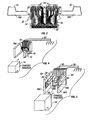
- Fig. 2 is a diagrammatic top plan view of an embodiment of the present invention in which the carriage connection flex cable of an ink-jet printer has extended portions for shunting to ground ESD from either of two pens.
- Fig. 3 is a top plan view of one configuration of the carriage connection flex cable utilized in the illustrated embodiment laid flat and before folding and mounting in the carriage of the printer of Fig. 2.
- Fig. 4 is a conceptual illustration of an alternate embodiment of our invention.
- Fig. 5 is a conceptual illustration of yet another alternate embodiment of our invention.
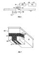
- Fig. 6 is a diagrammatic top plan view of a printer carriage equipped with an alternate embodiment of the present invention in which the carriage is shunted to ground.
- Fig. 7 is a diagrammatic illustration of a modified ink-jet pen having a pen flex cable with an extended portion for conveying ESD from the pen through the carriage of the printer of Fig. 6 and then to ground.
- an ink-jet pen 10 comprises an outer rectangular pen housing 12 with suitable projections and/or notches 14 for precision registration in the carriage.
- the pen housing 12 encloses at least one ink reservoir (not visible).
- a pen flex cable 16 wraps around a comer of the pen housing 12.
- One end of the pen flex cable 16 electrically connects with a plurality of resistors in a monolithic structure (not visible) associated with a nozzle plate 18 on a first side surface of the pen housing 12.
- Other ink-jet pen types may be used besides the thermal type, such as those employing piezoelectric devices.
- the other end of the pen flex cable 16 provides a plurality of electrically conductive contacts 20 on an adjacent second side surface of the pen housing 12.
- the pen housing 12 may be made of carbon filled plastic, although a static discharge can build up on the surface of other material from which the housing 12 can be fabricated. Substantial electrostatic charge can build up in the pen housing 12, particularly in dry climates, and especially when carried in the hand of a user who shuffles his or her feet over carpeting.
- the pen flex cable 16 may be made of a thin tape made of a suitable high strength plastic such as KAPTON® polyamide. Conductive traces such as 22 are formed on the pen flex cable 16 for providing electrical connection between the resistors and the conductive contacts 20. See for example U.S. Patent No. 5,748,209, the entire disclosure of which is hereby incorporated by reference.
- the contacts 20 (Fig. 1) of the pen 10 register with one set of corresponding raised conductive dimples 24 (Fig. 3) on the outer terminal end of a carriage connection flex cable 26 when the pen 10 is fully inserted into one side of a forwardly opening chute 28 (Fig. 2) of a carriage 30 of an ink-jet printer 32.
- the inner end of the carriage connection flex cable 26 is mated via suitable connector 33 to a carriage printed circuit assembly (PCA) 34.
- a suitable connector 35 connects the carriage PCA 34 to one end of a trailing flat flexible cable (FFC) 36.
- the other end of the trailing FFC 36 is connected to a stationary main PCA 37 through another suitable connector 38.
- the raised conductive dimples 24 on the carriage connection flex cable 26 receive various drive signals from the pen driver electronics on the carriage PCA 34.
- the digital data that allows the carriage PCA 34 to generate these drive signals comes from the main PCA 37 via FFC 36.
- the drive signals could also be generated on the main PCA 37 and be sent to the conductive dimples 24 via the FFC 36 and the PCA 34.
- the flexibility of the FFC 36 accommodates the reciprocating motion of the carriage 30, if any.
- the carriage 30 supports at least one color ink pen 10 or a black ink pen 42 in side-by-side relation within the carriage 30.
- the terminal end of the carriage connection flex cable 26 has two separate sets of dimples 24 as best seen in Fig. 3 which provide electrical connection with the separate sets of contacts of 20 the two different pens 10 and 42.
- the carriage 30 is slidably supported on a rail 44 for lateral reciprocation via belt drive 46 that is driven by belt motor 48 controlled by the belt motor drive electronics on the main PCA 37.
- Sets of pinch rollers 50 and 52 at opposite ends of the printer 32 propel a sheet of paper or other media 54 longitudinally through the printer 32.
- the pinch rollers 50 and 52 are driven by a motor 56 controlled by motor drive electronics on the main PCA 37.
- the pens 10 and 42 reciprocate laterally to print alphanumeric and/or graphic information on the media 54 such as that depicted at 57 in Fig. 2.
- the components of the printer 32 just described are supported on a common housing or frame denoted graphically at 58 for the sake of simplicity.
- the frame 58 may have metal components that serve as a ground, which may be further effectuated by a ground connection through a power supply 59 and AC power cord 60 with a grounded three-prong plug 60a.
- the printer may be of the page-wide array type in which the pens 10 and 42 do not move relative to the printer during printing.
- Both the ink-jet pens 10 and 42 (Fig. 2) and the carriage PCA 34 contain sensitive electronic components that are susceptible to permanent damage from ESD from the pens 10 and 42 or any object during their insertion into the carriage 30.
- This ESD can reach levels of about 15kV and higher.
- User insertion of a pen, such as the pen 10, into the carriage of the printer is regularly required when an empty pen is replaced. The user will often build up a static charge in his or her body walking across carpet which is transmitted to the pen 10 while it is held in his or her hand. Subsequent ESD can damage the pen 10 before it is ever inserted into the printer carriage 30.
- the carriage connection flex cable 24 has a pair of ears or extended portions 26a and 26b (Fig. 3) which are folded over and are angled rearwardly inside the chute 28.
- the flex cable 26 overlaps the three side walls of the carriage 30 as illustrated in Fig. 2.
- the extended portions 26a and 26b have conductive traces 61 and 62 (Fig. 3) which are forwardly exposed when the carriage connection flex cable 24 is mounted in the carriage 30.
- any ESD from the pen 42 travels through the connector 33 and through dedicated ground conductors in the carriage PCA 34 and trailing FFC 36 to the same ground conductor of the main PCA 37 and also does not damage or destroy any sensitive electronic components on the carriage PCA 34.
- the ESD is shunted to ground before the pen 10 or 42 is operatively mounted in the carriage 30.
- the carriage connection flex cable 24 may be made of KAPTON® polyamide or other suitable plastic film 64 with conductive traces 66 delineated thereon.
- the carriage connection flex cable is actually a flexible printed circuit (FPC).
- the traces 66 connect the raised sets of dimples 24 to a plurality of parallel conductors 68 that mate with the connector 33.
- the traces 61 and 62 that shunt ESD from the pens 10 and 42 to ground also lead to corresponding ones of the conductors 68.
- the corresponding extended portions 26a and 26b fold back rearwardly, allowing the conductive contacts 20 on the pens to mate with their corresponding conductive dimples 24.
- Each pen housing 12 physically contacts one of the extended portions 26a and 26b during an initial phase of insertion and folds them back.
- the resiliency of the carriage connection flex cable 26 results in the extended portions 26a and 26b springing back into their unfolded positions illustrated in Fig. 2 when the pens 10 and 42 are removed. This puts the extended portions 26a and 26b back into position to intercept any ESD from the next set of pens that are installed and shunt the same to ground.
- the chute 28 such as a user's index finger and the extended portions 26a and 26b should extend a substantial distance in order to ensure that the objects are intercepted and any ESD shunted to ground.
- Fig. 4 is a conceptual illustration of an alternate embodiment of our invention in which a carriage 72 is configured to receive a single pen 74.
- a carriage connection flex cable 76 has a single extended portion 76a which is bent and folded upwardly.
- the extended portion 76a has a forwardly exposed conductive trace 78 which forms a loop contact that touches the pen 74 before it is completely inserted into the carriage 72 and shunts ESD to ground through a ground path 80.
- the extended portion 76a folds back rearwardly and is sandwiched between the pen 74 and the rear wall of the carriage 72 when the pen 74 is fully inserted.
- the extended portion 76a is configured so that the conductive dimples 81 on the main part of the flex cable 76 are located in an open region bounded by the C-shaped extended portion 76a. Upon removal of the pen 74 the resilient extended portion 76a springs back forwardly into operative position for the next intercept.
- Fig. 5 is a conceptual illustration of yet another alternate embodiment of our invention in which a carriage 82 is configured to receive a single pen 84.
- a carriage connection flex cable 86 has a pair of extended portions 86a and 86b which are secured to the inside surfaces of the sidewalls 82a and 82b of the carriage.
- the extended portions 86a and 86b have exposed conductive pads 88 and 90 which touch the pen 84 before it is completely inserted into the carriage 82 and shunt ESD to ground through conductive traces 92 and 94 that connect to a ground path 96.
- Fig. 6 is a diagrammatic top plan view of a printer carriage 102 equipped with an alternate embodiment of the present invention in which the carriage 102 is shunted to ground.
- a carriage connection flex cable 104 without any extended portions is installed in the carriage 102.
- Fig. 7 is a diagrammatic illustration of a modified ink-jet pen 106 having a pen flex cable 108 with a resilient flexible extended portion 108a for conveying ESD from the pen 106 to a conductive pad 110 mounted on the inside of the sidewall of the carriage 102 (Fig. 6) and then to ground via ground path 112.
- the extended portion 108a (Fig. 7) is not tacked or otherwise secured to the pen housing 12 but projects outwardly from the pen housing 12.
- a crease or fold line 114 on the comer of the pen housing operates as a hinge.
- the extended portion 108a springs to its free floating intercept position in which it extends laterally away from the pen housing 12.
- an exposed region of a conductive trace 116 on the extended portion 108a of the pen flex cable 108 contacts the conductive pad 110 (Fig. 6) and any ESD from the pen 106 is shunted to ground.
- the extended portion 108a then folds rearwardly against the sidewall of the pen housing 12 and the conductive contacts 20 on the pen flex cable 108 register with their corresponding conductive dimples on the carriage connection flex cable 104.
- the extended portion 108a of the pen flex cable 108 bends around the comer of the pen housing 12 and then has a hump or raised area (not illustrated) that projects laterally outward from the pen housing 12.
- the outer end of the extended portion 108a is tacked to the pen housing 12 and an exposed region of the conductive trace 116 that traverses the hump contacts the conductive pad 110 (Fig. 6) during insertion of the pen 106 into the printer carriage 102.
- the exposed portions of the conductive traces 61, 62 and 78 and the conductive pads 88 and 90 that touch the pen housing 12 can be plated with gold to provide low ohm non-corroding contacts to ensure shunting of ESD. Other low ohmic plating metals and alloys can be used.
- the carriage connection flex cables 26, 76 and 86 can be fabricated from plastic film substrate with conductive traces formed thereon.
Landscapes
- Accessory Devices And Overall Control Thereof (AREA)
Applications Claiming Priority (2)
| Application Number | Priority Date | Filing Date | Title |
|---|---|---|---|
| US10/650,381 US6959980B2 (en) | 2003-08-27 | 2003-08-27 | ESD shielding of ink-jet printer |
| US650381 | 2003-08-27 |
Publications (1)
| Publication Number | Publication Date |
|---|---|
| EP1510345A1 true EP1510345A1 (de) | 2005-03-02 |
Family
ID=34104701
Family Applications (1)
| Application Number | Title | Priority Date | Filing Date |
|---|---|---|---|
| EP04016762A Withdrawn EP1510345A1 (de) | 2003-08-27 | 2004-07-15 | ESD-Schutz für einen Tintenstrahldrucker |
Country Status (2)
| Country | Link |
|---|---|
| US (1) | US6959980B2 (de) |
| EP (1) | EP1510345A1 (de) |
Families Citing this family (5)
| Publication number | Priority date | Publication date | Assignee | Title |
|---|---|---|---|---|
| US8438729B2 (en) * | 2006-03-09 | 2013-05-14 | Canon Kabushiki Kaisha | Method of producing liquid discharge head |
| JP2013226658A (ja) * | 2012-04-24 | 2013-11-07 | Seiko Epson Corp | 記録装置 |
| JP6024877B2 (ja) * | 2012-08-06 | 2016-11-16 | セイコーエプソン株式会社 | 記録装置 |
| JP6651908B2 (ja) * | 2016-03-03 | 2020-02-19 | ブラザー工業株式会社 | 液体吐出装置、及び、液体吐出装置の製造方法 |
| USD934341S1 (en) * | 2018-12-03 | 2021-10-26 | Hewlett-Packard Development Company, L.P. | Ink cartridge |
Citations (5)
| Publication number | Priority date | Publication date | Assignee | Title |
|---|---|---|---|---|
| JPH06143555A (ja) | 1992-11-10 | 1994-05-24 | Canon Inc | インクジェット記録装置 |
| US5359357A (en) | 1992-03-19 | 1994-10-25 | Fuji Xerox Co., Ltd. | Ink-jet recording apparatus |
| EP0641667A2 (de) | 1993-09-08 | 1995-03-08 | Canon Kabushiki Kaisha | Aufzeichnungsgerät mit einer Vorrichtung zum Entfernen von statischen Ladungen |
| EP0993954A2 (de) * | 1998-10-06 | 2000-04-19 | Hewlett-Packard Company | Tintenstrahldrucksystem das eine modulare Tintenpatronenbaugruppe verwendet |
| US6168262B1 (en) * | 1997-01-30 | 2001-01-02 | Hewlett-Packard Company | Electrical interconnect for replaceable ink containers |
Family Cites Families (5)
| Publication number | Priority date | Publication date | Assignee | Title |
|---|---|---|---|---|
| EP0490668B1 (de) | 1990-12-12 | 1996-10-16 | Canon Kabushiki Kaisha | Tintenstrahlaufzeichnung |
| US5635968A (en) | 1994-04-29 | 1997-06-03 | Hewlett-Packard Company | Thermal inkjet printer printhead with offset heater resistors |
| US5748209A (en) | 1994-10-31 | 1998-05-05 | Hewlett-Packard Company | Thermal ink jet tab circuit having a plurality of trace groups wherein adjacent traces in each group are staggered |
| US6361150B1 (en) | 1999-08-30 | 2002-03-26 | Hewlett-Packard Company | Electrostatic discharge protection of electrically-inactive components in a thermal ink jet printing system |
| JP2003145770A (ja) | 2001-11-15 | 2003-05-21 | Canon Inc | 記録ヘッド用基板、記録ヘッド、記録装置、および記録ヘッドの製造方法 |
-
2003
- 2003-08-27 US US10/650,381 patent/US6959980B2/en not_active Expired - Fee Related
-
2004
- 2004-07-15 EP EP04016762A patent/EP1510345A1/de not_active Withdrawn
Patent Citations (5)
| Publication number | Priority date | Publication date | Assignee | Title |
|---|---|---|---|---|
| US5359357A (en) | 1992-03-19 | 1994-10-25 | Fuji Xerox Co., Ltd. | Ink-jet recording apparatus |
| JPH06143555A (ja) | 1992-11-10 | 1994-05-24 | Canon Inc | インクジェット記録装置 |
| EP0641667A2 (de) | 1993-09-08 | 1995-03-08 | Canon Kabushiki Kaisha | Aufzeichnungsgerät mit einer Vorrichtung zum Entfernen von statischen Ladungen |
| US6168262B1 (en) * | 1997-01-30 | 2001-01-02 | Hewlett-Packard Company | Electrical interconnect for replaceable ink containers |
| EP0993954A2 (de) * | 1998-10-06 | 2000-04-19 | Hewlett-Packard Company | Tintenstrahldrucksystem das eine modulare Tintenpatronenbaugruppe verwendet |
Non-Patent Citations (1)
| Title |
|---|
| PATENT ABSTRACTS OF JAPAN vol. 0184, no. 52 (M - 1661) 23 August 1994 (1994-08-23) * |
Also Published As
| Publication number | Publication date |
|---|---|
| US20050046670A1 (en) | 2005-03-03 |
| US6959980B2 (en) | 2005-11-01 |
Similar Documents
| Publication | Publication Date | Title |
|---|---|---|
| US11945231B2 (en) | Printing material container, and board mounted on printing material container | |
| JP3126277B2 (ja) | 記録装置 | |
| RU2501660C2 (ru) | Контейнер для печатающего материала | |
| CN1189415A (zh) | 可更换墨盒的电连接 | |
| JP2013151094A (ja) | 液体噴射ヘッドモジュール及び液体噴射装置 | |
| CN116766776B (zh) | 墨盒芯片、墨盒及喷墨打印设备 | |
| US6959980B2 (en) | ESD shielding of ink-jet printer | |
| US6554380B2 (en) | Method for detecting a liquid used for discharge, and a liquid discharging device | |
| CN114475003B (zh) | 耗材容器、耗材芯片与电子成像设备 | |
| CN220390739U (zh) | 墨盒 | |
| JP4468495B2 (ja) | 印字装置 | |
| JP3733243B2 (ja) | 記録装置 | |
| JPH02206579A (ja) | インクジェットプリンタ | |
| JPS6329572Y2 (de) | ||
| US6921155B2 (en) | Electrically grounded conductive ESD shunt mechanism for fluid-ejection mechanism | |
| JP7844236B2 (ja) | 液体吐出装置 | |
| CN218615930U (zh) | 印刷装置以及电子设备 | |
| JP2000141698A (ja) | インクジェットプリンタ | |
| JP2678078B2 (ja) | サーマルプリンタ | |
| JP2002025644A (ja) | 接地構造及び記録装置 | |
| US12187050B2 (en) | Printing apparatus | |
| CN221137275U (zh) | 芯片组件和成像材料盒 | |
| JP2002240391A (ja) | 画像形成装置及び配線ケーブル | |
| JP2001315408A (ja) | インクジェットプリンタ | |
| US7081022B2 (en) | Electrical apparatus having card insertion slot and combined printing apparatus having card insertion slot |
Legal Events
| Date | Code | Title | Description |
|---|---|---|---|
| PUAI | Public reference made under article 153(3) epc to a published international application that has entered the european phase |
Free format text: ORIGINAL CODE: 0009012 |
|
| AK | Designated contracting states |
Kind code of ref document: A1 Designated state(s): AT BE BG CH CY CZ DE DK EE ES FI FR GB GR HU IE IT LI LU MC NL PL PT RO SE SI SK TR |
|
| AX | Request for extension of the european patent |
Extension state: AL HR LT LV MK |
|
| 17P | Request for examination filed |
Effective date: 20050214 |
|
| AKX | Designation fees paid |
Designated state(s): DE FR GB |
|
| 17Q | First examination report despatched |
Effective date: 20130715 |
|
| GRAP | Despatch of communication of intention to grant a patent |
Free format text: ORIGINAL CODE: EPIDOSNIGR1 |
|
| INTG | Intention to grant announced |
Effective date: 20140530 |
|
| STAA | Information on the status of an ep patent application or granted ep patent |
Free format text: STATUS: THE APPLICATION IS DEEMED TO BE WITHDRAWN |
|
| 18D | Application deemed to be withdrawn |
Effective date: 20141010 |