EP1510287B1 - Appareil pour serrer un outil dans un porte-outil - Google Patents
Appareil pour serrer un outil dans un porte-outil Download PDFInfo
- Publication number
- EP1510287B1 EP1510287B1 EP04014271A EP04014271A EP1510287B1 EP 1510287 B1 EP1510287 B1 EP 1510287B1 EP 04014271 A EP04014271 A EP 04014271A EP 04014271 A EP04014271 A EP 04014271A EP 1510287 B1 EP1510287 B1 EP 1510287B1
- Authority
- EP
- European Patent Office
- Prior art keywords
- tool
- chuck
- carrier unit
- opening
- tool chuck
- Prior art date
- Legal status (The legal status is an assumption and is not a legal conclusion. Google has not performed a legal analysis and makes no representation as to the accuracy of the status listed.)
- Expired - Lifetime
Links
- 238000001816 cooling Methods 0.000 claims description 40
- 238000000034 method Methods 0.000 description 5
- 238000010438 heat treatment Methods 0.000 description 4
- 238000013461 design Methods 0.000 description 3
- 230000037230 mobility Effects 0.000 description 3
- 238000012545 processing Methods 0.000 description 3
- 230000006698 induction Effects 0.000 description 2
- 238000005259 measurement Methods 0.000 description 2
- 238000006073 displacement reaction Methods 0.000 description 1
- 230000000694 effects Effects 0.000 description 1
- 238000000605 extraction Methods 0.000 description 1
- 230000002349 favourable effect Effects 0.000 description 1
- 238000003754 machining Methods 0.000 description 1
- 238000012423 maintenance Methods 0.000 description 1
- 230000000630 rising effect Effects 0.000 description 1
Images



Classifications
-
- B—PERFORMING OPERATIONS; TRANSPORTING
- B23—MACHINE TOOLS; METAL-WORKING NOT OTHERWISE PROVIDED FOR
- B23Q—DETAILS, COMPONENTS, OR ACCESSORIES FOR MACHINE TOOLS, e.g. ARRANGEMENTS FOR COPYING OR CONTROLLING; MACHINE TOOLS IN GENERAL CHARACTERISED BY THE CONSTRUCTION OF PARTICULAR DETAILS OR COMPONENTS; COMBINATIONS OR ASSOCIATIONS OF METAL-WORKING MACHINES, NOT DIRECTED TO A PARTICULAR RESULT
- B23Q17/00—Arrangements for observing, indicating or measuring on machine tools
- B23Q17/09—Arrangements for observing, indicating or measuring on machine tools for indicating or measuring cutting pressure or for determining cutting-tool condition, e.g. cutting ability, load on tool
- B23Q17/0904—Arrangements for observing, indicating or measuring on machine tools for indicating or measuring cutting pressure or for determining cutting-tool condition, e.g. cutting ability, load on tool before or after machining
- B23Q17/0919—Arrangements for measuring or adjusting cutting-tool geometry in presetting devices
- B23Q17/0923—Tool length
-
- B—PERFORMING OPERATIONS; TRANSPORTING
- B23—MACHINE TOOLS; METAL-WORKING NOT OTHERWISE PROVIDED FOR
- B23P—METAL-WORKING NOT OTHERWISE PROVIDED FOR; COMBINED OPERATIONS; UNIVERSAL MACHINE TOOLS
- B23P11/00—Connecting or disconnecting metal parts or objects by metal-working techniques not otherwise provided for
- B23P11/02—Connecting or disconnecting metal parts or objects by metal-working techniques not otherwise provided for by first expanding and then shrinking or vice versa, e.g. by using pressure fluids; by making force fits
- B23P11/025—Connecting or disconnecting metal parts or objects by metal-working techniques not otherwise provided for by first expanding and then shrinking or vice versa, e.g. by using pressure fluids; by making force fits by using heat or cold
- B23P11/027—Connecting or disconnecting metal parts or objects by metal-working techniques not otherwise provided for by first expanding and then shrinking or vice versa, e.g. by using pressure fluids; by making force fits by using heat or cold for mounting tools in tool holders
-
- B—PERFORMING OPERATIONS; TRANSPORTING
- B23—MACHINE TOOLS; METAL-WORKING NOT OTHERWISE PROVIDED FOR
- B23Q—DETAILS, COMPONENTS, OR ACCESSORIES FOR MACHINE TOOLS, e.g. ARRANGEMENTS FOR COPYING OR CONTROLLING; MACHINE TOOLS IN GENERAL CHARACTERISED BY THE CONSTRUCTION OF PARTICULAR DETAILS OR COMPONENTS; COMBINATIONS OR ASSOCIATIONS OF METAL-WORKING MACHINES, NOT DIRECTED TO A PARTICULAR RESULT
- B23Q3/00—Devices holding, supporting, or positioning work or tools, of a kind normally removable from the machine
- B23Q3/155—Arrangements for automatic insertion or removal of tools, e.g. combined with manual handling
- B23Q3/1552—Arrangements for automatic insertion or removal of tools, e.g. combined with manual handling parts of devices for automatically inserting or removing tools
Definitions
- the invention relates to a device for fastening a tool in a tool chuck according to the preamble of patent claim 1.
- WO 03/002298 A1 discloses a device for fastening a tool in a tool chuck, in particular a shrink chuck.
- the device has a magazine with a loading and unloading station, in which the tool and the tool chuck can be used by a user before a fastening operation of the tool in the tool chuck.
- the device comprises a control system into which data required for the fastening process can be entered by the operator and / or loaded from a database. The control system may, after inserting the tool, inserting the tool chuck and inputting and / or loading the data, control in particular all the moving means to be moved for a fastening operation.
- a first moving means of the device is the magazine, which can bring the loading and unloading station by means of a rotary movement in a removal position.
- the device comprises a tool gripper which holds the tool chuck by means of at least one vertical extension movement, pick at least one horizontal method and at least one rotational movement of the removal position and can use in a spindle.
- a holding means for holding the tool is arranged for positioning the tool in the tool chuck on a cross slide, wherein the cross slide in the vertical direction and the holding means are movable in the horizontal direction.
- the holding means is also designed for a rotational movement about a tool axis.
- the device also comprises an opening device designed as an induction unit for opening the tool chuck for a tool holder, which can be moved at least in the vertical direction, but can also be designed for movability in the horizontal direction and rotational movement about the tool axis.
- the tool gripper can reset a complete tool including the tool chuck and the tool mounted in the tool chuck in a reverse order of movement as in retrieving the tool chuck into the loading and unloading station. From there it can be supplied for example by a rotary movement of a finishing, in particular a cooling.
- the device therefore has a number of degrees of freedom separately movable means.
- the invention is therefore in particular the object of specifying a device for fixing the tool in the tool chuck, with which a tool can be fixed in a tool chuck with relatively few independently movable means.
- the invention is particularly based on a device for fastening a tool in a tool chuck, which comprises an opening means for opening the tool chuck for a tool holder and a holding means for holding the tool.
- a carrier unit on which the opening means and the holding means are arranged, wherein at least one movement of the carrier unit as a whole, both the opening means and the tool by means of the holding means are movable relative to the tool chuck.
- the opening means may in particular be a means for heating, whereby a shrink chuck which must be heated for a tool holder can be used as the tool chuck.
- the attachment can be fully automatic and without intervention by an operator, so that dangers for an operator can be kept low.
- both the opening means and by the movement of the carrier unit the tool can be positioned over the tool chuck with the aid of the holding means. It can be saved on the tool chuck more drives for separate positioning of the opening means and the tool.
- the carrier unit is rotatable about an axis which is aligned in particular parallel to a longitudinal axis of the tool chuck. Due to the rotatability of the carrier unit, a particularly compact and stable design of the carrier unit can be used. In particular, by a parallel alignment of the axis of the carrier unit to the longitudinal axis of the tool chuck can also achieve advantages in a simple and compact design of the device. Compared with an example translational movement of the carrier unit, the drives for the rotatable about the axis carrier unit can be designed particularly economical, since the inertia can be kept lower in a rotational movement.
- a means for finishing a complete tool is arranged on the carrier unit, wherein the complete tool comprises the tool chuck and the tool mounted in the tool chuck. If the finishing of the complete tool is necessary or expedient, the means for finishing can also be arranged on the carrier unit. As a result, a separate device for finishing can be saved.
- the finishing of the complete tool may, for example, be a cooling of the shrink chuck so that the complete tool can be removed from the device for attaching the tool without risk of burns for an operator.
- further means for positioning and / or machining the tool on the carrier unit may be arranged, such as a grinding device or a measuring device for measuring a complete tool or tool.
- the support unit comprises a support on which a means for positioning is movably arranged, wherein the opening means and the means for finishing are arranged on the means for positioning.
- a separate drive for the opening means or the means for finishing can be saved.
- the means for positioning along a rotational axis of the carrier unit is movable. By concentrating the movements of the means along and about the axis of the carrier unit, the drives can be arranged close to each other, whereby, inter alia, a power supply can be made simple and clear.
- the means for finishing can be positioned in a position suitable for finishing the complete tool. If the means for finishing can be positioned by a movement of the carrier unit, further drives for moving the means for finishing can be saved.
- the means for finishing a cooling device for cooling the tool chuck with at least a first cooling unit having a tool receiving aperture having a first diameter and a second cooling unit having a tool receiving aperture having a second diameter greater than the first diameter.
- the cooling device can be used for tool chuck with different diameters.
- the cooling device comprises a fastening means and a rotator rotatably mounted on the fastening means and carrying the first and second cooling units.
- the cooling units can be arranged in a particularly space-saving manner.
- the opening means, the holding means and the means for finishing by the carrier unit in the longitudinal axis of the tool chuck are movable.
- the operations of opening, holding and finishing can take place in a confined space, which in particular makes it easy to monitor operations and accessibility for unscheduled operations.
- the means are all moved over the tool chuck, so that they only have to be lowered into a processing position.
- the device comprises a tool measuring device, by means of which a tool positioned in the longitudinal axis can be measured.
- a position of the tool can be determined, and by means of the measured values, the tool can be positioned exactly in the tool chuck.
- the processing operations can be monitored in detail by the measuring device. It is also conceivable by means of the measuring device to measure the tool - optionally mounted in the tool chuck - outside of a mounting operation.
- the movement of the carrier unit as a whole is a rotary movement
- the holding means, the opening means and the means for finishing are arranged offset in the direction of rotation a maximum of 60 ° to each other.
- the distance between the holding means and the opening means and between the holding means and the means for finishing is smaller than the distance between the opening means and the means for finishing. This can also be realized by short ways a particularly short processing time.
- the angle indications and the distance indications refer in each case to the locations at which a tool longitudinal axis is arranged in the opening means, holding means and means for finishing.
- FIG. 1 shows a device 2 for fastening a tool 4 in a tool chuck 6 configured as a shrink chuck in a basic position.
- the tool 4 is in one Tool provision 7 and the tool chuck 6 used in a spindle 8. Also indicated by dashed lines is the tool 4 fastened in the tool chuck 6 after a fastening process.
- a support unit 10 is shown, which is rotatably mounted about an axis 12 and which comprises a table 14 and a support 16.
- a means 18 is arranged for positioning, which is vertically movable in the direction of a double arrow 20 on the support 16.
- the inductor 32 has a suction device, not shown, for the extraction of steam rising from the tool chuck 6.
- a holding arm 24 Positioned on the means 18 for positioning is a holding arm 24 which carries a cooling device 26.
- the cooling device 26 comprises a rotator 28 which is rotatably mounted about an axis 30.
- the rotator 28 carries six cooling units 34, each having a different width tool receiving opening 58 ( Figure 2) for cooling various tools.
- a support member 36 On the support unit 10, a support member 36 is further attached, on which in turn a holding means 38 is arranged.
- the holding means 38 is a gripper for gripping the tool 4.
- the holding means 38 can be moved vertically along a double arrow 40 on the carrier element 36.
- a tool measuring device 42 On the left in FIG. 1, a tool measuring device 42 is shown with a measuring optics 46 which can be moved vertically on a measuring support 44.
- FIG. 2 shows a plan view of the device 2 from FIG. 1 in accordance with a direction II - II.
- the tool measuring device 42 is shown with the measuring support 44 and the measuring optics 46, between which the concealed tool 4 in the longitudinal axis 52 of the hidden tool chuck 6 can be measured.
- the axis 12 is perpendicular to the plane of representation.
- This perspective shows that the cooling device 26 is arranged via the holding arm 24 and the opening means 22 via a further holding arm 54 on the means 18 for positioning.
- the rotator 28 of the cooling device 26 is positioned so that one of the tool receiving openings 58 is positioned in the longitudinal axis 52 of the tool chuck 6. By means of a corresponding rotation about the axis 30, all further tool receiving openings 58 can be moved into the longitudinal axis 52 of the tool chuck 6.
- Above the invisible tool provision 7 is the holding means 38.
- FIG. 3 shows a further plan view of the device 2.
- Three locations 60 are marked, which are positioned in the longitudinal axis 52 of the tool chuck 6 in a process for fastening the tool 4 in the tool chuck 6.
- the locations 60 are arranged in the opening means 22, in the holding means 38 and in the cooling device 26.
- Places 60 also serve as reference points for distance and angle indications.
- s 1 denotes a distance between the holding means 38 and the opening means 22 and s 2 a distance between the opening means 22 and the cooling device 26.
- r 1 a distance of the locations 60 from the axis 12 is designated.
- the holding means 38 has a round housing 62, which is positioned above the tool chuck 6 concentrically about the longitudinal axis of the tool chuck 6.
- the holding means 38 is shown in somewhat greater detail.
- the holding means 38 has a housing 62, rollers 64 for holding and rotating the indicated tool 4 and clamping carriage 66 for receiving different tool diameter.
- the rollers 64 In a rest position of the clamping carriage 66, the rollers 64 are positioned as far as possible in the direction of three double arrows 68 outside.
- the holding means 38 can be adjusted to different tool diameters.
- One of the rollers 64 is designed as a drive roller, so that a rotation of the fixed tool 4 is possible.
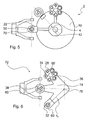
- FIG. 5 shows a further plan view of the device 2.
- the opening means 22 is located in the longitudinal axis 52 of the concealed tool chuck 6.
- the opening means 22 has a round tool receiving opening 70 which is positioned over the tool chuck 6 concentrically about the longitudinal axis of the tool chuck 6.
- the tool chuck 6 is first inserted into the spindle 8.
- the Device 2 is in the basic position shown in Figure 1.
- the tool 4 to be fastened is inserted into the tool supply 7.
- a possibly existing backup can be activated, for example a door can be closed, and an automatic sequence can be started.
- the holding means 38 is moved in the direction of the double arrow 40 on the carrier element 36 down until the tool 4 used in the tool supply 7 is enclosed. Now the clamping slide 66 of the holding means 38 from its rest position ( Figure 4) so long in the direction of the double arrow 68 moved inwards until the tool 4 is held securely by the rollers 64. Subsequently, the holding means 38 is moved up again, so that the holding means 38 can be rotated with the held tool 4 by rotation of the carrier unit 10 via the tool chuck 6. After a rotational movement of the carrier unit 10, which is a 45 ° clockwise rotation in this embodiment, the tool 4 is positioned concentrically about the tool chuck 6 about the longitudinal axis of the tool chuck 6 (FIG. 3).
- the measuring optics 46 is moved vertically from a starting position into a position suitable for measuring. Then the drive roller of the holding means 38 ( Figure 4) rotates, whereby the tool 4 in the holding means 38 is also rotated. During the rotational movement, the tool 4 and in particular one or more tool cutting edges are measured. After measuring the measuring optics 46 is moved back to its original position.
- the carrier unit 10 is rotated by a further 45 ° in a clockwise direction, so that the inductor 32 is positioned above the tool chuck 6 concentrically about the longitudinal axis 52 of the tool chuck 6 (FIG. 5).
- the inductor 32 is moved in the direction of the double arrow 20 ( Figure 1) down until it encloses the part of the tool chuck 6, which is provided for heating.
- the inductor 32 is supplied with electric current, whereby the intended for heating part of the tool chuck 6 heats and expands. Thereafter, the inductor 32 is moved up again.
- the carrier unit 10 is rotated by 45 ° counterclockwise, so that the held in the holding means 38 tool 4 is again positioned over the now widened tool chuck 6.
- the tool 4 is then introduced downwards into the tool chuck 6 by a movement of the holding means 38 and precisely positioned there by means of the values obtained by the measurement.
- the clamping carriages 66 of the holding means 38 are displaced outwards in the direction of the double arrow 68 into their rest position.
- the holding means 38 is moved up again.
- the carrier unit 10 is once again rotated by 45 ° counterclockwise, so that the cooling device 26 is positioned in the longitudinal axis 52 of the tool chuck 6 above the tool chuck 6 ( Figure 2).
- the each to be cooled Tool chuck 6 matching cooling unit 34 has already been positioned by a corresponding rotation of the rotator 28 so that it can be brought by a subsequent movement of the means 18 for positioning down in a suitable for cooling the tool chuck 6 position.
- the cooling device 26 is moved upwards again by the positioning means 18, and the complete tool comprising the tool chuck 6 and the tool 4 fastened in the tool chuck 6 is removed after opening the possibly existing door.
- the device 2 is back in its normal position and is ready for a new fastening operation.
- the attachment process can be fully automatic. Intervention or support by an operator is not necessary.
- the cooling device 26, the holding means 38 and the inductor 32 are arranged in the embodiment shown on the carrier unit 10 in the direction of rotation of the carrier unit 10 so that the respective closest local means is the next in chronological use on the tool chuck 6. Therefore, the carrier unit 10 is rotated per rotational movement only by a small angle, in particular 45 °, between the cooling device 26 and the holding means 38 or between the holding means 38 and the inductor 32.
- the support unit 10 For possible adjustment and maintenance, the support unit 10 but also rotatable at larger angles.
- FIG. 6 shows an alternative embodiment of a device 72 for fastening a tool in a plan view.
- a carrier unit 74 is rotatable about an axis 76, wherein the axis 76 is perpendicular to the plane of representation.
- the carrier unit 74 along the axis 76 is movable.
- the carrier unit 74 has three arms, at the ends of which the opening means 22, the holding means 38 and the cooling device 26 are arranged. A distance of the locations 60 from the axis 76 is indicated by r 2 .
- the attachment of a tool 4 in the tool chuck 6 with the device 72 is carried out analogously as with the device 2.
- the carrier unit 74 also handles the vertical positioning operations of the holding means 38, the inductor 32 and the cooling units 34.
- FIG. 7 shows a second alternative exemplary embodiment of a device 78 for fastening a tool 4 in a tool chuck 6 in a plan view.
- the inductor 32, the holding means 38 and the cooling units 34 which are arranged separately on a star-shaped carrier unit 80.
- the carrier unit 80 is designed to be rotatable about a carrier support 82 or about an axis 84. In this embodiment, the distance of the locations 60 from the axis 84 is indicated by r 3 .
- Figure 8 shows a side view of the embodiment of Figure 7 according to a direction VIII - VIII.
- the support unit 80 can also be moved in the vertical direction on the Carrier support 82 is arranged.
- a vertical mobility of the support unit 80 eliminates a separate movement of the holding means 38.
- the cooling units 34 on the support unit 80 the rotator 28 and a separate movement of the cooling units 34 omitted by the rotator 28th
- This embodiment changes to the effect that the carrier unit 80 performs the necessary for an attachment of the tool 4 in the tool chuck 6 positioning operations of the holding means 38, the inductor 32 and the cooling units 34.
- the carrier unit 80 performs the necessary for an attachment of the tool 4 in the tool chuck 6 positioning operations of the holding means 38, the inductor 32 and the cooling units 34.
Landscapes
- Engineering & Computer Science (AREA)
- Mechanical Engineering (AREA)
- Automatic Tool Replacement In Machine Tools (AREA)
- Gripping On Spindles (AREA)
- Devices For Opening Bottles Or Cans (AREA)
- Processing Of Terminals (AREA)
Claims (12)
- Dispositif (2, 72, 78) pour fixer un outil (4) dans un mandrin d'outil (6), qui comprend un moyen d'ouverture (22) pour l'ouverture du mandrin d'outil (6) pour un logement d'outil et un moyen de retenue (38) pour retenir l'outil (4),
caractérisé par
une unité de support (10, 74, 80) sur laquelle sont disposés le moyen d'ouverture (22) et le moyen de retenue (38), au moins un mouvement de l'unité de support (10, 74, 80) dans son ensemble permettant de déplacer à la fois le moyen d'ouverture (22) et l'outil (4) à l'aide du moyen de retenue (38) par rapport au mandrin d'outil (6). - Dispositif (2, 72, 78) selon la revendication 1,
caractérisé en ce que
le moyen d'ouverture (22) ainsi que l'outil (4) peuvent être positionnés à l'aide du moyen de retenue (38) par-dessus le mandrin d'outil (6) par le mouvement de l'unité de support (10, 74, 80). - Dispositif (2, 72, 78) selon l'une quelconque des revendications précédentes,
caractérisé en ce que
l'unité de support (10, 74, 80) est montée à rotation autour d'un axe (12, 76, 84), qui est orienté notamment parallèlement à un axe longitudinal (52) du mandrin d'outil (6). - Dispositif (2, 72, 78) selon l'une quelconque des revendications précédentes,
caractérisé en ce qu'
un moyen d'usinage final d'un outil complet, notamment un dispositif de refroidissement (26), est disposé sur l'unité de support (10, 74, 80), l'outil complet comprenant le mandrin d'outil (6) et l'outil (4) fixé dans le mandrin d'outil (6). - Dispositif (2, 72, 78) selon la revendication 4,
caractérisé en ce que
l'unité de support (10, 74, 80) comprend un montant de support sur lequel est disposé un moyen déplaçable pour le positionnement, le moyen d'ouverture (22) et le moyen d'usinage final étant disposés sur le moyen de positionnement. - Dispositif (2, 72, 78) selon la revendication 4 ou 5, caractérisé en ce que
par au moins un mouvement de l'unité de support (10, 74, 80) dans son ensemble, le moyen d'usinage final peut être positionné dans une position appropriée pour l'usinage final de l'outil complet. - Dispositif (2, 72, 78) selon l'une quelconque des revendications 4 à 6,
caractérisé en ce que
le moyen d'usinage final est un dispositif de refroidissement (26) pour refroidir le mandrin d'outil (6) avec au moins une première unité de refroidissement (34) avec une ouverture de logement d'outil (58) ayant un premier diamètre et une deuxième unité de refroidissement (34) avec une ouverture de logement d'outil (58) ayant un deuxième diamètre, qui est supérieur au premier diamètre. - Dispositif (2, 72) selon la revendication 7,
caractérisé en ce que
le dispositif de refroidissement (26) comprend un moyen de fixation et un dispositif de rotation (28) monté à rotation sur le moyen de fixation, portant la première et la deuxième unité de support (34). - Dispositif (2, 72, 78) selon l'une quelconque des revendications 4 à 8,
caractérisé en ce que
le moyen d'ouverture (22), le moyen de retenue (38) et le moyen d'usinage final peuvent être déplacés par l'unité de support (10, 74, 80) dans l'axe longitudinal (52) du mandrin d'outil (6). - Dispositif (2, 72, 78) selon la revendication 9,
caractérisé par
un dispositif de mesurage (42) qui permet de mesurer un outil (4) positionné dans l'axe longitudinal (52). - Dispositif (2, 72, 78) selon l'une quelconque des revendications 4 à 10,
caractérisé en ce que
le mouvement de l'unité de support (10, 74, 80) dans son ensemble est un mouvement de rotation et le moyen de retenue (38), le moyen d'ouverture (22) et le moyen d'usinage final sont disposés de manière décalée l'un par rapport à l'autre dans la direction de rotation de 60° au maximum. - Dispositif (2, 72, 78) selon l'une quelconque des revendications 4 à 11,
caractérisé en ce que
la distance (s1) entre le moyen de retenue (38) et le moyen d'ouverture (22) ainsi qu'entre le moyen de retenue (38) et le moyen d'usinage final est inférieure à la distance (s2) entre le moyen d'ouverture (22) et le moyen d'usinage final.
Applications Claiming Priority (2)
| Application Number | Priority Date | Filing Date | Title |
|---|---|---|---|
| DE10339419 | 2003-08-27 | ||
| DE10339419A DE10339419A1 (de) | 2003-08-27 | 2003-08-27 | Vorrichtung zum Befestigen eines Werkzeugs in einem Werkzeugfutter |
Publications (2)
| Publication Number | Publication Date |
|---|---|
| EP1510287A1 EP1510287A1 (fr) | 2005-03-02 |
| EP1510287B1 true EP1510287B1 (fr) | 2006-11-08 |
Family
ID=34089213
Family Applications (1)
| Application Number | Title | Priority Date | Filing Date |
|---|---|---|---|
| EP04014271A Expired - Lifetime EP1510287B1 (fr) | 2003-08-27 | 2004-06-18 | Appareil pour serrer un outil dans un porte-outil |
Country Status (3)
| Country | Link |
|---|---|
| EP (1) | EP1510287B1 (fr) |
| AT (1) | ATE344710T1 (fr) |
| DE (2) | DE10339419A1 (fr) |
Families Citing this family (9)
| Publication number | Priority date | Publication date | Assignee | Title |
|---|---|---|---|---|
| DE102005003927B4 (de) * | 2005-01-28 | 2009-08-27 | E. Zoller GmbH & Co. KG Einstell- und Messgeräte | Vorrichtung zum Befestigen eines Werkzeugs in einem Werkzeugfutter |
| ITMI20100908A1 (it) * | 2010-05-20 | 2011-11-21 | Speroni Spa | Dispositivo di raffreddamento e di riscaldamento integrato ed automatico per utensili e calettamento |
| CN103128313B (zh) * | 2012-08-20 | 2015-05-20 | 贵州詹阳动力重工有限公司 | 采用立式车床加工挖掘机转臂架主传动孔的方法及夹具 |
| DE102015118516B4 (de) | 2015-10-29 | 2020-08-06 | Wilhelm Diemer | Vorrichtung zur Handhabung und Bearbeitung von Werkstücken sowie Vorrichtung und Verfahren zum Fügen wenigstens eines Fügeteils mit einem Werkstück |
| CN105290883A (zh) * | 2015-12-03 | 2016-02-03 | 成都飞机工业(集团)有限责任公司 | 一种数控机床验刀方法 |
| CN105500114A (zh) * | 2015-12-30 | 2016-04-20 | 山东大学 | 一种数控机床导电式验刀仪 |
| DE202018104875U1 (de) * | 2018-08-24 | 2018-10-19 | Haimer Gmbh | Schrumpfgerät mit Futtererkennung und automatischer Spulenverstellung |
| DE102019108904A1 (de) * | 2019-04-04 | 2020-10-08 | E. Zoller GmbH & Co. KG Einstell- und Messgeräte | Ein- und/oder Ausschrumpfspannstation für Werkzeuge und Verfahren mit einer Ein- und/oder Ausschrumpfspannstation für Werkzeuge |
| DE102021117584A1 (de) * | 2021-07-07 | 2023-01-12 | E. Zoller GmbH & Co. KG Einstell- und Messgeräte | Schrumpfspannsystem mit Kühleinheit |
Family Cites Families (3)
| Publication number | Priority date | Publication date | Assignee | Title |
|---|---|---|---|---|
| FR2768071B1 (fr) * | 1997-09-05 | 1999-11-12 | E P B Emile Pfalzgraf | Dispositif pour l'assemblage et le desassemblage d'un outil avec un porte-outils |
| DE10131352A1 (de) * | 2001-06-26 | 2003-01-09 | Zoller Gmbh & Co Kg E | Verfahren und Vorrichtung zum Einschrumpfen von Werkzeugen, insbesondere Zerspanungswekzeugen |
| DE10222092B4 (de) * | 2001-11-12 | 2015-02-12 | Franz Haimer Maschinenbau Kg | Schrumpfvorrichtung für einen Werkzeughalter |
-
2003
- 2003-08-27 DE DE10339419A patent/DE10339419A1/de not_active Withdrawn
-
2004
- 2004-06-18 AT AT04014271T patent/ATE344710T1/de not_active IP Right Cessation
- 2004-06-18 EP EP04014271A patent/EP1510287B1/fr not_active Expired - Lifetime
- 2004-06-18 DE DE502004001939T patent/DE502004001939D1/de not_active Expired - Lifetime
Also Published As
| Publication number | Publication date |
|---|---|
| EP1510287A1 (fr) | 2005-03-02 |
| ATE344710T1 (de) | 2006-11-15 |
| DE502004001939D1 (de) | 2006-12-21 |
| DE10339419A1 (de) | 2005-03-24 |
Similar Documents
| Publication | Publication Date | Title |
|---|---|---|
| DE3886979T2 (de) | Stanzvorrichtung für dünne Platten und in der Vorrichtung verwendete Stanzeinheiten. | |
| DE19860492B4 (de) | Programmgesteuerte Fräs- und Bohrmaschine | |
| DE69710444T2 (de) | Vorrichtung zum Laden von Rohren auf Bearbeitungsmaschinen, insbesondere auf Rohrbiegemaschinen | |
| DE60206979T2 (de) | Mehrachsige Handwerkzeugmaschine | |
| EP1399292B1 (fr) | Procede et dispositif permettant de fixer des outils a des mandrins de serrage | |
| DE3322444A1 (de) | Vorrichtung zum wechseln von werkzeugen | |
| DE2628428C3 (de) | Adapter zum Verbinden von Anschluß- und/oder Prüfpunkten einer Baugruppe mit einer Mefischaltung | |
| DE3138483A1 (de) | "vorrichtung zum positionieren, verbinden und bearbeiten von bauteilen" | |
| EP3453487B1 (fr) | Procédé de positionnement d'un point central sur un axe géométrique dans une machine-outil | |
| DE1477737A1 (de) | Werkzeugmaschine mit mehreren Werkzeughaltern | |
| WO2019052859A1 (fr) | Magasin à outils et procédé de changement d'outils | |
| EP3739697B1 (fr) | Dispositif ainsi que procédé de confection automatique d'une paire de lignes | |
| DE19919645A1 (de) | Werkzeugmaschine mit Werkzeugspindel und Revolverkopf | |
| EP1510287A1 (fr) | Appareil pour serrer un outil dans un porte-outil | |
| EP0321699A1 (fr) | Magasin additionel pour machines-outils commandées par programme | |
| EP3664959B1 (fr) | Procédé et dispositif de fourniture de vis | |
| EP1194266B1 (fr) | Dispositif de changement d'outil destine a une machine-outil | |
| EP0949029B1 (fr) | Machine outil pour l'usinage des barres | |
| EP0144912A2 (fr) | Changeur d'outil pour fraiseuses et perceuses | |
| EP1402985A2 (fr) | Dispositif de serrage | |
| WO2016120477A1 (fr) | Machine-outil et procédé, en particulier de fabrication flexible plus efficace de modèles d'usinage au moyen de plusieurs axes | |
| DE3876431T2 (de) | Auswechselgeraet fuer freitragende walzen in walzgeruesten. | |
| DE4234446C1 (de) | Werkzeugwechsler | |
| DE3135082C2 (de) | "Vorrichtung zum Befestigen von Kraftfahrzeugteilen bei Montage- und/oder Reparaturarbeiten" | |
| DE2319092B2 (de) | Bürstenherstellungsmaschine |
Legal Events
| Date | Code | Title | Description |
|---|---|---|---|
| PUAI | Public reference made under article 153(3) epc to a published international application that has entered the european phase |
Free format text: ORIGINAL CODE: 0009012 |
|
| AK | Designated contracting states |
Kind code of ref document: A1 Designated state(s): AT BE BG CH CY CZ DE DK EE ES FI FR GB GR HU IE IT LI LU MC NL PL PT RO SE SI SK TR |
|
| AX | Request for extension of the european patent |
Extension state: AL HR LT LV MK |
|
| 17P | Request for examination filed |
Effective date: 20050806 |
|
| AKX | Designation fees paid |
Designated state(s): AT BE BG CH CY CZ DE DK EE ES FI FR GB GR HU IE IT LI LU MC NL PL PT RO SE SI SK TR |
|
| GRAP | Despatch of communication of intention to grant a patent |
Free format text: ORIGINAL CODE: EPIDOSNIGR1 |
|
| GRAS | Grant fee paid |
Free format text: ORIGINAL CODE: EPIDOSNIGR3 |
|
| GRAA | (expected) grant |
Free format text: ORIGINAL CODE: 0009210 |
|
| AK | Designated contracting states |
Kind code of ref document: B1 Designated state(s): AT BE BG CH CY CZ DE DK EE ES FI FR GB GR HU IE IT LI LU MC NL PL PT RO SE SI SK TR |
|
| PG25 | Lapsed in a contracting state [announced via postgrant information from national office to epo] |
Ref country code: RO Free format text: LAPSE BECAUSE OF FAILURE TO SUBMIT A TRANSLATION OF THE DESCRIPTION OR TO PAY THE FEE WITHIN THE PRESCRIBED TIME-LIMIT Effective date: 20061108 Ref country code: FI Free format text: LAPSE BECAUSE OF FAILURE TO SUBMIT A TRANSLATION OF THE DESCRIPTION OR TO PAY THE FEE WITHIN THE PRESCRIBED TIME-LIMIT Effective date: 20061108 Ref country code: SI Free format text: LAPSE BECAUSE OF FAILURE TO SUBMIT A TRANSLATION OF THE DESCRIPTION OR TO PAY THE FEE WITHIN THE PRESCRIBED TIME-LIMIT Effective date: 20061108 Ref country code: IE Free format text: LAPSE BECAUSE OF FAILURE TO SUBMIT A TRANSLATION OF THE DESCRIPTION OR TO PAY THE FEE WITHIN THE PRESCRIBED TIME-LIMIT Effective date: 20061108 Ref country code: PL Free format text: LAPSE BECAUSE OF FAILURE TO SUBMIT A TRANSLATION OF THE DESCRIPTION OR TO PAY THE FEE WITHIN THE PRESCRIBED TIME-LIMIT Effective date: 20061108 Ref country code: CZ Free format text: LAPSE BECAUSE OF FAILURE TO SUBMIT A TRANSLATION OF THE DESCRIPTION OR TO PAY THE FEE WITHIN THE PRESCRIBED TIME-LIMIT Effective date: 20061108 Ref country code: SK Free format text: LAPSE BECAUSE OF FAILURE TO SUBMIT A TRANSLATION OF THE DESCRIPTION OR TO PAY THE FEE WITHIN THE PRESCRIBED TIME-LIMIT Effective date: 20061108 Ref country code: NL Free format text: LAPSE BECAUSE OF FAILURE TO SUBMIT A TRANSLATION OF THE DESCRIPTION OR TO PAY THE FEE WITHIN THE PRESCRIBED TIME-LIMIT Effective date: 20061108 |
|
| REG | Reference to a national code |
Ref country code: GB Ref legal event code: FG4D Free format text: NOT ENGLISH |
|
| REG | Reference to a national code |
Ref country code: CH Ref legal event code: EP |
|
| REG | Reference to a national code |
Ref country code: IE Ref legal event code: FG4D Free format text: LANGUAGE OF EP DOCUMENT: GERMAN |
|
| REF | Corresponds to: |
Ref document number: 502004001939 Country of ref document: DE Date of ref document: 20061221 Kind code of ref document: P |
|
| PG25 | Lapsed in a contracting state [announced via postgrant information from national office to epo] |
Ref country code: DK Free format text: LAPSE BECAUSE OF FAILURE TO SUBMIT A TRANSLATION OF THE DESCRIPTION OR TO PAY THE FEE WITHIN THE PRESCRIBED TIME-LIMIT Effective date: 20070208 Ref country code: SE Free format text: LAPSE BECAUSE OF FAILURE TO SUBMIT A TRANSLATION OF THE DESCRIPTION OR TO PAY THE FEE WITHIN THE PRESCRIBED TIME-LIMIT Effective date: 20070208 Ref country code: BG Free format text: LAPSE BECAUSE OF FAILURE TO SUBMIT A TRANSLATION OF THE DESCRIPTION OR TO PAY THE FEE WITHIN THE PRESCRIBED TIME-LIMIT Effective date: 20070208 |
|
| PG25 | Lapsed in a contracting state [announced via postgrant information from national office to epo] |
Ref country code: ES Free format text: LAPSE BECAUSE OF FAILURE TO SUBMIT A TRANSLATION OF THE DESCRIPTION OR TO PAY THE FEE WITHIN THE PRESCRIBED TIME-LIMIT Effective date: 20070219 |
|
| PG25 | Lapsed in a contracting state [announced via postgrant information from national office to epo] |
Ref country code: PT Free format text: LAPSE BECAUSE OF FAILURE TO SUBMIT A TRANSLATION OF THE DESCRIPTION OR TO PAY THE FEE WITHIN THE PRESCRIBED TIME-LIMIT Effective date: 20070409 |
|
| NLV1 | Nl: lapsed or annulled due to failure to fulfill the requirements of art. 29p and 29m of the patents act | ||
| ET | Fr: translation filed | ||
| GBV | Gb: ep patent (uk) treated as always having been void in accordance with gb section 77(7)/1977 [no translation filed] |
Effective date: 20061108 |
|
| REG | Reference to a national code |
Ref country code: IE Ref legal event code: FD4D |
|
| PLBE | No opposition filed within time limit |
Free format text: ORIGINAL CODE: 0009261 |
|
| STAA | Information on the status of an ep patent application or granted ep patent |
Free format text: STATUS: NO OPPOSITION FILED WITHIN TIME LIMIT |
|
| 26N | No opposition filed |
Effective date: 20070809 |
|
| PG25 | Lapsed in a contracting state [announced via postgrant information from national office to epo] |
Ref country code: GB Free format text: LAPSE BECAUSE OF FAILURE TO SUBMIT A TRANSLATION OF THE DESCRIPTION OR TO PAY THE FEE WITHIN THE PRESCRIBED TIME-LIMIT Effective date: 20061108 |
|
| BERE | Be: lapsed |
Owner name: E.ZOLLER G.M.B.H. & CO.KG EINSTELL-UND MESSGERATE Effective date: 20070630 |
|
| PG25 | Lapsed in a contracting state [announced via postgrant information from national office to epo] |
Ref country code: MC Free format text: LAPSE BECAUSE OF NON-PAYMENT OF DUE FEES Effective date: 20070630 |
|
| PG25 | Lapsed in a contracting state [announced via postgrant information from national office to epo] |
Ref country code: BE Free format text: LAPSE BECAUSE OF NON-PAYMENT OF DUE FEES Effective date: 20070630 |
|
| PG25 | Lapsed in a contracting state [announced via postgrant information from national office to epo] |
Ref country code: GR Free format text: LAPSE BECAUSE OF FAILURE TO SUBMIT A TRANSLATION OF THE DESCRIPTION OR TO PAY THE FEE WITHIN THE PRESCRIBED TIME-LIMIT Effective date: 20070209 |
|
| PG25 | Lapsed in a contracting state [announced via postgrant information from national office to epo] |
Ref country code: AT Free format text: LAPSE BECAUSE OF NON-PAYMENT OF DUE FEES Effective date: 20070618 |
|
| PG25 | Lapsed in a contracting state [announced via postgrant information from national office to epo] |
Ref country code: EE Free format text: LAPSE BECAUSE OF FAILURE TO SUBMIT A TRANSLATION OF THE DESCRIPTION OR TO PAY THE FEE WITHIN THE PRESCRIBED TIME-LIMIT Effective date: 20061108 |
|
| PG25 | Lapsed in a contracting state [announced via postgrant information from national office to epo] |
Ref country code: LU Free format text: LAPSE BECAUSE OF NON-PAYMENT OF DUE FEES Effective date: 20070618 Ref country code: CY Free format text: LAPSE BECAUSE OF FAILURE TO SUBMIT A TRANSLATION OF THE DESCRIPTION OR TO PAY THE FEE WITHIN THE PRESCRIBED TIME-LIMIT Effective date: 20061108 |
|
| PG25 | Lapsed in a contracting state [announced via postgrant information from national office to epo] |
Ref country code: TR Free format text: LAPSE BECAUSE OF FAILURE TO SUBMIT A TRANSLATION OF THE DESCRIPTION OR TO PAY THE FEE WITHIN THE PRESCRIBED TIME-LIMIT Effective date: 20061108 Ref country code: HU Free format text: LAPSE BECAUSE OF FAILURE TO SUBMIT A TRANSLATION OF THE DESCRIPTION OR TO PAY THE FEE WITHIN THE PRESCRIBED TIME-LIMIT Effective date: 20070509 |
|
| REG | Reference to a national code |
Ref country code: CH Ref legal event code: NV Representative=s name: THOMAS DAUB, CH |
|
| PGFP | Annual fee paid to national office [announced via postgrant information from national office to epo] |
Ref country code: CH Payment date: 20140620 Year of fee payment: 11 Ref country code: DE Payment date: 20140625 Year of fee payment: 11 Ref country code: IT Payment date: 20140624 Year of fee payment: 11 |
|
| PGFP | Annual fee paid to national office [announced via postgrant information from national office to epo] |
Ref country code: FR Payment date: 20140617 Year of fee payment: 11 |
|
| REG | Reference to a national code |
Ref country code: DE Ref legal event code: R119 Ref document number: 502004001939 Country of ref document: DE |
|
| PG25 | Lapsed in a contracting state [announced via postgrant information from national office to epo] |
Ref country code: IT Free format text: LAPSE BECAUSE OF NON-PAYMENT OF DUE FEES Effective date: 20150618 |
|
| REG | Reference to a national code |
Ref country code: CH Ref legal event code: PL |
|
| REG | Reference to a national code |
Ref country code: FR Ref legal event code: ST Effective date: 20160229 |
|
| PG25 | Lapsed in a contracting state [announced via postgrant information from national office to epo] |
Ref country code: DE Free format text: LAPSE BECAUSE OF NON-PAYMENT OF DUE FEES Effective date: 20160101 Ref country code: LI Free format text: LAPSE BECAUSE OF NON-PAYMENT OF DUE FEES Effective date: 20150630 Ref country code: CH Free format text: LAPSE BECAUSE OF NON-PAYMENT OF DUE FEES Effective date: 20150630 |
|
| PG25 | Lapsed in a contracting state [announced via postgrant information from national office to epo] |
Ref country code: FR Free format text: LAPSE BECAUSE OF NON-PAYMENT OF DUE FEES Effective date: 20150630 |