EP1509791B1 - Light guide within recessed housing - Google Patents
Light guide within recessed housing Download PDFInfo
- Publication number
- EP1509791B1 EP1509791B1 EP03718394A EP03718394A EP1509791B1 EP 1509791 B1 EP1509791 B1 EP 1509791B1 EP 03718394 A EP03718394 A EP 03718394A EP 03718394 A EP03718394 A EP 03718394A EP 1509791 B1 EP1509791 B1 EP 1509791B1
- Authority
- EP
- European Patent Office
- Prior art keywords
- light
- light guide
- illumination apparatus
- recess
- notches
- Prior art date
- Legal status (The legal status is an assumption and is not a legal conclusion. Google has not performed a legal analysis and makes no representation as to the accuracy of the status listed.)
- Expired - Lifetime
Links
- 238000005286 illumination Methods 0.000 claims abstract description 56
- 238000000605 extraction Methods 0.000 claims description 24
- 238000000034 method Methods 0.000 claims description 3
- 230000005540 biological transmission Effects 0.000 claims 1
- 239000002537 cosmetic Substances 0.000 abstract description 6
- 230000001815 facial effect Effects 0.000 abstract description 3
- 239000007787 solid Substances 0.000 description 4
- 238000000576 coating method Methods 0.000 description 2
- 238000007689 inspection Methods 0.000 description 2
- XLYOFNOQVPJJNP-UHFFFAOYSA-N water Substances O XLYOFNOQVPJJNP-UHFFFAOYSA-N 0.000 description 2
- 239000003086 colorant Substances 0.000 description 1
- 230000008878 coupling Effects 0.000 description 1
- 238000010168 coupling process Methods 0.000 description 1
- 238000005859 coupling reaction Methods 0.000 description 1
- 230000001419 dependent effect Effects 0.000 description 1
- 238000009792 diffusion process Methods 0.000 description 1
- 230000000694 effects Effects 0.000 description 1
- 238000004519 manufacturing process Methods 0.000 description 1
- 239000000463 material Substances 0.000 description 1
- 230000013011 mating Effects 0.000 description 1
- 238000005065 mining Methods 0.000 description 1
- 238000012986 modification Methods 0.000 description 1
- 230000004048 modification Effects 0.000 description 1
- 230000003287 optical effect Effects 0.000 description 1
- 239000000843 powder Substances 0.000 description 1
- 238000000926 separation method Methods 0.000 description 1
- 230000003746 surface roughness Effects 0.000 description 1
- 230000000007 visual effect Effects 0.000 description 1
Images


Classifications
-
- G—PHYSICS
- G02—OPTICS
- G02B—OPTICAL ELEMENTS, SYSTEMS OR APPARATUS
- G02B6/00—Light guides; Structural details of arrangements comprising light guides and other optical elements, e.g. couplings
-
- G—PHYSICS
- G02—OPTICS
- G02B—OPTICAL ELEMENTS, SYSTEMS OR APPARATUS
- G02B6/00—Light guides; Structural details of arrangements comprising light guides and other optical elements, e.g. couplings
- G02B6/0001—Light guides; Structural details of arrangements comprising light guides and other optical elements, e.g. couplings specially adapted for lighting devices or systems
- G02B6/0005—Light guides; Structural details of arrangements comprising light guides and other optical elements, e.g. couplings specially adapted for lighting devices or systems the light guides being of the fibre type
- G02B6/001—Light guides; Structural details of arrangements comprising light guides and other optical elements, e.g. couplings specially adapted for lighting devices or systems the light guides being of the fibre type the light being emitted along at least a portion of the lateral surface of the fibre
-
- F—MECHANICAL ENGINEERING; LIGHTING; HEATING; WEAPONS; BLASTING
- F21—LIGHTING
- F21V—FUNCTIONAL FEATURES OR DETAILS OF LIGHTING DEVICES OR SYSTEMS THEREOF; STRUCTURAL COMBINATIONS OF LIGHTING DEVICES WITH OTHER ARTICLES, NOT OTHERWISE PROVIDED FOR
- F21V33/00—Structural combinations of lighting devices with other articles, not otherwise provided for
-
- F—MECHANICAL ENGINEERING; LIGHTING; HEATING; WEAPONS; BLASTING
- F21—LIGHTING
- F21S—NON-PORTABLE LIGHTING DEVICES; SYSTEMS THEREOF; VEHICLE LIGHTING DEVICES SPECIALLY ADAPTED FOR VEHICLE EXTERIORS
- F21S43/00—Signalling devices specially adapted for vehicle exteriors, e.g. brake lamps, direction indicator lights or reversing lights
- F21S43/20—Signalling devices specially adapted for vehicle exteriors, e.g. brake lamps, direction indicator lights or reversing lights characterised by refractors, transparent cover plates, light guides or filters
- F21S43/235—Light guides
-
- F—MECHANICAL ENGINEERING; LIGHTING; HEATING; WEAPONS; BLASTING
- F21—LIGHTING
- F21V—FUNCTIONAL FEATURES OR DETAILS OF LIGHTING DEVICES OR SYSTEMS THEREOF; STRUCTURAL COMBINATIONS OF LIGHTING DEVICES WITH OTHER ARTICLES, NOT OTHERWISE PROVIDED FOR
- F21V33/00—Structural combinations of lighting devices with other articles, not otherwise provided for
- F21V33/0004—Personal or domestic articles
- F21V33/0048—Office articles, e.g. bookmarks, desk lamps with drawers, stands for books or music scores
-
- F—MECHANICAL ENGINEERING; LIGHTING; HEATING; WEAPONS; BLASTING
- F21—LIGHTING
- F21W—INDEXING SCHEME ASSOCIATED WITH SUBCLASSES F21K, F21L, F21S and F21V, RELATING TO USES OR APPLICATIONS OF LIGHTING DEVICES OR SYSTEMS
- F21W2121/00—Use or application of lighting devices or systems for decorative purposes, not provided for in codes F21W2102/00 – F21W2107/00
- F21W2121/02—Use or application of lighting devices or systems for decorative purposes, not provided for in codes F21W2102/00 – F21W2107/00 for fountains
Definitions
- the invention relates to light guides for functional or decorative lighting.
- Light guides can be used to provide functional or decorative lighting.
- Functional lighting refers to lighting that is used for the purpose of illuminating an object or area to make the object or area more conspicuous.
- Decorative lighting refers to lighting that is used for aesthetic purposes. Often, light guides are used for both functional and decorative purposes.
- a light source can be used to illuminate one or more light guides such that light is transmitted through the light guides via total internal reflection (TIR).
- Light guides may provide side lighting, in which light is emitted from the sides of the guides.
- light guides may provide end lighting, in which light is emitted from the end of the guides.
- a variety of different light extraction techniques using notches or coatings, for example, can be applied to the light guides to cause light to be emitted from the sides of the light guides in a controlled or random manner.
- Lighting systems that implement light guides generally have one or more light sources that illuminate the light guide.
- incandescent light sources, or solid state light sources such as light emitting diodes are often used to illuminate light guides.
- the light source may reside in a light source assembly, also referred to as an illuminator.
- the light can be transmitted down the light guide, and may change colors or pulsate over time to provide the desired functional or decorative effect.
- US-A-4 805 984 discloses a hollow, tubular light conduit including a wall of a transparent polymeric material, and the wall having a structured surface and an opposite, smooth, glossy surface, and at least a portion of the cross section of the wall lying in a smooth arcuate curve, wherein light striking the inner surface, within an acceptable angular range, is contained by total internal reflection.
- the invention is directed to an illumination apparatus that includes a light guide within a recessed housing.
- a light source such as a light emitting diode can be used to provide light to the light guide.
- the light is transmitted through the light guide via total internal reflection (TIR), and can be extracted in a controlled manner to ensure that a desired angular distribution of light is achieved without substantially illuminating interior side walls of the recessed housing. In this manner, emission of light outward from the illumination apparatus can be enhanced, providing efficient lighting from a more compact structure.
- TIR total internal reflection
- the invention is directed to an illumination apparatus comprising a housing formed with a recess, wherein the recess includes one or more interior walls.
- the illumination apparatus also includes a light guide positioned substantially within the recess such that the light guide is in proximity to the interior walls.
- the light guide can be formed with one or more light extraction features, such as notches, that define an angular distribution of light emitted from the light guide.
- the light extraction features can be defined such that the angular distribution of light emitted from the light guide causes light to be angularly dispersed from the recess without substantially illuminating the interior side walls of the recess.
- Various embodiments of the invention may find use in a number of applications, including lighting fixtures and the like.
- One specific embodiment, outlined in greater detail below, relates to a cosmetic compact that includes a mirror.
- the compact may incorporate aspects of the invention by implementing a light guide within a ring-shaped recess of the compact to provide facial lighting to a user of the compact.
- the compact can maintain a relatively small form-factor because the light guide is positioned within the recessed housing.
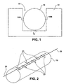
- FIG. 1 is a cross-sectional view of a light guide 10 housed within a recessed housing 12.
- recessed housing 12 is formed with recess 14 which includes one or more interior walls 15, 16.
- recess 14 may include interior side walls 15A, 15B and interior back wall 16.
- Light guide 10 is positioned substantially within recess 14 such that light guide 10 is in proximity to the interior walls.
- light guide 10 is formed with one or more light extraction features that define an angular distribution of light emitted laterally from light guide 10.
- the light extraction features may comprise coatings, notches, or any other suitable light extraction features.
- the light extraction features can define the angular distribution of light emitted from the light guide such that light is angularly dispersed from recess 14 without substantially illuminating one or more of the interior side walls 15.
- the light extraction features may serve to direct light outward from recess 14 such that substantial illumination of side walls 15A and 15B can be minimized or avoided. In this manner, more efficient lighting can be achieved.
- the need to provide mirrored or reflective surfaces on one or more interior walls 15, 16 to achieve the efficient lighting can be avoided.
- Recess 14 of housing 12 can provide a useful structure for defining the positioning of light guide 10.
- recess 14 may define a path which forms various 2-dimensional or 3-dimensional shapes such as for example, characters, numbers, geometric shapes, or other aesthetically desirable shapes or configurations.
- recess 14 of housing can provide a useful tool for positioning or suspending light guide 10.
- one embodiment described in greater detail below implements a light guide within a ring-shaped recess of a cosmetic compact.
- one or more interior walls 15, 16 may be roughened to reduce or avoid optical coupling between light guide 10 and housing 12.
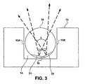
- FIG. 2 is a perspective view of a suitable light guide 10 that may be used in accordance with one or more embodiments of the invention.
- light guide 10 is formed with sets of notches 21 and 22, which cause light to be emitted from light guide 10 according to an angular distribution that can achieve effective and efficient light distribution from the recessed housing.
- light guide 10 may comprise a light guide substantially as described in U.S. Patent 5,845,038 .
- Such light guides are commercially available from Minnesota Mining and Manufacturing Company ("3M") of St. Paul, Minnesota.
- Light guide 10 may include a first set of notches 21 formed on light guide 10 along a first centerline axis 25, as well as a second set of notches 22 formed on light guide 10 along a second centerline axis 26.
- first notches 21 are substantially centered on centerline axis 25, whereas second notches 22 are substantially centered on axis 26.
- the first and second centerline axes 25, 26 can be defined relative to one another to ensure that the angular distribution of light emitted from light guide 10 is relatively large, but does not inefficiently illuminate interior side walls 15 of recess 14 (FIG. 1).
- the angular distribution of light emitted from light guide 10 can be substantially maximized without illuminating the interior side walls 15 of recess 14.
- Light intensity may also be substantially maximized without illuminating the interior side walls 15 of recess 14.
- Other variables, such as the ratios of the depths of the notches to the diameter of the light guide may also be chosen to ensure that the desired angular distribution and light intensity is achieved.
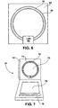
- FIG. 3 is a more detailed cross-sectional view of light guide 10 housed within recessed housing 12.
- first notches 21 define a light extraction angle ⁇ 1.
- second notches 22 define light extraction angle ⁇ 2.
- Angles ⁇ 1 and ⁇ 2 may depend on one or more factors including the ratios of the depths of the notches to the diameter of light guide 10, the angle at which light is introduced into light guide, and possibly other factors. Any number of sets of notches can be implemented. In any case, the light extraction angles associated with the sets of notches overlap with one another to define angle ⁇ .
- Angle ⁇ may be dependent on the angular size of each of light extraction angles ⁇ 1 and ⁇ 2, as well as the angular distance (offset) between centerline axes of the notches that respectively define light extraction angles ⁇ 1 and ⁇ 2.
- angle ⁇ can be defined such that emitted light is angularly dispersed for effective and efficient lighting, specifically when light guide 10 is housed within recess 14.
- angle ⁇ is defined such that interior side walls 15 of recess 14 are not substantially illuminated, avoiding inefficient loss of light. Illumination of interior side walls 15 can result in inefficient use of the available light transmitted through light guide 10 via total internal reflection (TIR). In addition, illumination of interior side walls 15 can result in lighting artifacts and/or shadowing that is often undesirable. By avoiding illumination of side walls 15, greater lighting efficiency can be achieved and the need for mirrored or reflective surfaces within recess 14 can also be avoided. For these reasons, angle ⁇ is defined such that illumination of interior side walls 15 is substantially avoided.
- ⁇ can defined such that emitted light is angularly dispersed so that a very high level of light extraction efficiency can be achieved from light guide 10 housed within housing 12.
- high efficiency optically smooth notches may be used to extract a large amount of light from light guide 10.
- high efficiency optically smooth notches can be used to extract greater than 70 percent of the light introduced into light guide 10 by an LED in a direction defined by ⁇ , i.e., away from recess 14.
- Optically smooth notches generally refer to notches that have smooth surfaces capable of reflecting light incident on the surface with minimal scattering or diffusion. In other words, the surface roughness may be small in comparison to the wavelength of light being transmitted through light guide 10 via total internal reflection (TIR).
- stray light may escape through the notches themselves, e.g., in a direction that illuminates back wall 16. For example less than 10 percent or even less than 5 percent of light introduced into light guide 10 may illuminate back wall 16. Approximately 20 percent of the light introduced into light guide 10 may propagate down the length of light guide 10 without being extracted. In this example, less than 5 percent, less than 1 percent, or even less than 0.25 percent of the light introduced into light guide 10 may illuminate side walls 15. In this manner, efficient use of the available light can be achieved, and at the same time shadowing or lighting artifacts associated with the illumination of side walls 15 can be avoided.
- FIGS. 4 and 5 are additional cross-sectional side views of a light guide 10 housed within a recessed housing 12.
- the interior walls of the recessed housing 12 may take a number of different shapes.
- side walls 15A and 15B may be angled to facilitate even larger extraction angles from light guide 10, without substantially illuminating the side walls.
- end wall 15C may be contoured to substantially conform to the shape of light guide 10.
- the cross-sectional shape of light guide 10 may take any number of different shapes, including a circular shape, as illustrated. Depending on the cross-sectional shape of light guide 10, different shapes of the interior walls may be desirable.
- light guide 10 is illustrated in FIGS. 1, 4 and 5 as being positioned completely within recess 14 of recessed housing 12, in other configurations, light guide 10 may be only partially positioned within recess 14 of recessed housing 12.
- the shape of the recess itself may also be defined as desired.
- the top view of the recess may define any shape.
- FIG. 6 is a top view of light guide 10 housed within a recessed housing 64 that is formed with a ring-shaped recess 66.
- Other shaped recesses could also be implemented, including triangular-like shapes, square-like shapes, pentagon-like shapes, hexagon-like shapes, and so forth.
- Variations of the ring-shape can also be implemented, for example, as circular-shapes, oval-shapes, elliptical-shapes, and so forth.
- the shape of the recess may define letters, symbols, characters, or the like.
- the recess may be defined along a contoured or 3-dimensional shape.
- the recess may be a spiraled recess formed around a pole.
- the shape of the recess may take any form, including forms defined in 2-dimensions or 3-dimensions.
- Light guide 10 can be embedded into the contour of the recess in order to position light guide 10 according to a desired shape.
- the recessed housing can provide a useful structure to suspend the light guide, or otherwise define the mechanical positioning of the light guide. In this manner, the recessed housing can provide the ability to define a variety of atheistically pleasing shapes for the light guide, including letters, symbols, characters, geometric shapes, 3-dimensional shapes, and the like. Automotive (vehicle) lighting may also utilize various aspects of the invention, for example, to provide lighting for visual mirrors, signal lights, brake lights, instrument panels, or the like.
- one or more solid state light sources such as light emitting diodes (LED) 68 can be used to provide light to light guide 10.
- LED light emitting diodes
- light emitting diodes may be disposed on both ends of light guide 10, or alternatively a single LED may be disposed to provide light into a first end of light guide 10. In the latter case, the second end of light guide 10 may have a reflective surface to redirect light back through light guide 10.
- Other light sources could also be used.
- ring-shaped recess 66 may provide room for a wire which connects the LEDs.
- a light guide housed within a recessed housing as described herein may be used to realize various different types of lighting fixtures.
- a light guide housed within a recessed housing may be used within a variety of different device structures and gadgets.
- the recessed configuration may be a useful feature for smaller sized structures that require lighting, because the recessed configuration can save space.
- FIG. 7 is a front perspective view illustrating one specific application of light guide within a recessed housing.
- FIG. 7 illustrates a cosmetic compact 70.
- Compact 70 includes a light guide 10 housed within housing 72 that is formed with a ring-shaped recess 73.
- One or more LEDs 74 illuminate light guide 10.
- a mirrored surface is disposed in an interior region 75 defined by the ring-shaped recess 73.
- Compact 70 may also include one or more accessories 78, and possibly a make-up region 79 for storing facial make-up, powder, or the like.
- FIG. 8 is a cross-sectional side view of a portion of a compact according to an embodiment of the invention. Specifically, FIG. 8 corresponds to a cross-sectional side view of light guide 10 within the ring-shaped recess 73 of housing 72. As shown, an approximately 5 millimeter diameter light guide is disposed within the recess 73 of housing 72, although light guides having various different diameters could be used. Recess 73 forms a ring-shape as illustrated in FIG. 7, and a diameter of the ring-shaped recess may be approximately 7.25 centimeters. More generally, the diameter may be approximately between 2 and 50 centimeters, or approximately between 5 and 10 centimeters for useful application in a compact or similar lighted structure. A mirrored surface 86 can be provided in an interior region defined by ring-shaped recess 73. The recessed configuration can reduce the overall thickness of compact 70, which is desirable.
- Sets of notches, or other suitable light extraction features may be formed or provided on light guide 10 in order to achieve a desired angular distribution of light emitted from light guide 10.
- the desired angular distribution may be defined according to a desired illumination plane located a distance above mirrored surface 86, for example, to improve lighting of the face of a user.
- the desired angular distribution may ensure that one or more interior side walls of recess 73 are not substantially illuminated. By avoiding illumination of the walls of recess 73, inefficient use of light may be reduced, and various unwanted lighting artifacts and shadowing can also be avoided.
- one or more notches may have different orientations, such as orientations that are not perpendicular to a longitudinal axis of light guide 10.
- a first set of notches 87 are located along a centerline approximately 5 degrees from points of the light guide in closest proximity to a bottom surface 90 of recess 73 in a direction toward a center of housing 72.
- a second set of notches 88 are located along a centerline approximately 30 degrees from points of the light guide in closest proximity to a bottom surface 90 of recess 73 in a direction away from the center of housing 72.
- the positioning of the notches may be adjusted for other embodiments, the angles listed above have proven effective for a cosmetic compact. For example, greater than approximately 50 percent light illumination efficiency for a compact can be achieved at a specifically defined illumination plane when the sets of notches are disposed at such angles, as further outlined below. Additional sets of notches may also be used.
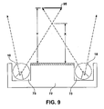
- FIG. 9 is another cross-sectional side view of the portion of a compact illustrated in FIG. 8.
- the emitted light (indicated by the dotted lines) exiting light guide 10 has an angular distribution that ensures that one or more interior side walls of recess 73 are not substantially illuminated.
- the angular distribution of emitted light is defined in a manner that establishes an illumination target 95 within an illumination plane.
- the angular distribution of emitted light can cause light to overlap at a distance X, typically between 2 and 50 centimeters from housing 72.
- the illumination plane that defines the location of target 95 may be defined at a distance Y, typically between 5 and 50 centimeters from housing 72.
- the angular distribution of emitted light can be chosen such that the size of target 95 is large enough to ensure that adequate illumination of the face of a user is achieved. Moreover, the positioning of the notches can be such that greater than approximately 50 percent of the light transmitted through light guide 10 illuminates the illumination target 95.
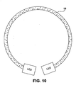
- FIG. 10 is a top view of a ring-shaped notched light guide that can be used according to one or more embodiments of the invention.
- light guide 10 is illuminated by LEDs positioned on each end of light guide 10. Illuminating both ends of light guide 10 may enhance uniformity of the light intensity of emitted light over the length of light guide 10.
- the notches may be approximately 0.3 millimeter deep and may have included notch angles of approximately 80 degrees, although the invention is not necessarily limited in that respect. In some cases, variables such as notch angles notch depths, spacing between notches, spacing between rows of notches, or the number of rows of notches can be chosen to achieve a desired lighting goal. Also, one or more of these variables can be varied or adjusted over the length of light guide 10 to effectuate more uniform intensity of emitted light.
- the notches may be separated from one another by approximately 1.5 millimeters, although the invention is not necessarily limited in that respect.
- the first set of notches (in this case illustrated as being a row of notches adjacent the inner diameter of light guide 10) can be disposed approximately 5 degrees from points of light guide 10 that will be positioned in closest proximity to a bottom surface of the recessed housing in a direction toward a center of the housing.
- the second set of notches (in this case illustrated as being the row of notches adjacent the inner diameter of light guide 10) can be disposed approximately 30 degrees from points of light guide 10 that will be positioned in closest proximity to a bottom surface of the recessed housing in a direction away from a center of the housing.
- the sets of notches can be arranged such that two notches in the first set separate each notch in the second set. Other configurations can also be implemented.
- FIG. 11 is another cross-sectional side view of a light guide 10 housed within a recessed housing 72 according to an embodiment of the invention.
- three different sets of notches are formed on light guide 10. More specifically, different sets of notches are disposed in the following manner. The first set of notches are disposed approximately 11 degrees from points of light guide 10 that are positioned in closest proximity to a bottom surface of the recessed housing in a direction toward a center of the housing.
- the second set of notches are disposed approximately 5 degrees from points of light guide 10 that are positioned in closest proximity to a bottom surface of the recessed housing in a direction toward a center of the housing.
- the third set of notches are disposed approximately 1 degree from points of light guide 10 that are positioned in closest proximity to a bottom surface of the recessed housing in a direction away from a center of the housing.
- Recessed housing 72 is formed with a mirrored surface 86 on the region inside the ring-shaped recess 73 of recessed housing 72.
- the positioning, separation, and arrangements of the sets of notches can be defined in a manner that ensures that efficient and effective lighting is achieved when the light guide is housed in a recess.
- Other variables that can be adjusted may include the diameter of the light guide, the length of the light guide, the shape and size of the recess, the notch depths, the number of notches, the type of light source used, the number of light sources used, and possibly other variables.
- aspects of the invention may be implemented to realize other types of ring-lighting structures that incorporate a ring-shaped light guide within a ring-shaped recess.
- ring-shaped lighting may be effective for devices such as inspection equipment, image acquisition equipment, photography equipment, lighted magnifiers, night lights, watches, badges, signs and the like.
- FIG. 12 is a perspective exploded view of an assembly that can be used according to one or more embodiments of the invention. Although FIG. 12 is not necessarily drawn to scale, a similar arrangement can be used to illuminate light guide 10. As shown, the apparatus 100 of FIG. 12 includes a light emitting diode 112 and a light guide 10. Apparatus 100 may also include a light guide fixture 118 formed with a hole 120 for mating with light guide 110. For example, light guide fixture 118 can be used to properly position light guide 10 relative to light emitting diode 112. Apparatus 100 may also include heat sink 124 to dissipate heat away from light emitting diode 112, and a connector 126 coupled to light emitting diode 112.
- connector 126 may be used to connect light emitting diode 112 to a power supply (not shown).
- Light emitting diode 112 may reside on plate 113, although the invention is not limited in that respect.
- Apparatus 100, or a similar structure, may be housed within a device, with light guide 10 residing within a recessed housing as outlined above.
- Fixture 118, plate 113, heat sink 124, and connector 126 may be sized much smaller than illustrated in FIG. 12 to realize a illumination apparatus with a smaller form-factor.
- Suitable light emitting diodes include, for example, the LuxeonTM Star/C commercially available from LumiLeds of San Jose, California; the Nichia NSPW 500 BS LED, commercially available from Nichia Corporation of Japan; a three color LED such as model.NSCM310, available from Nichia Corporation of Japan; or a white LED such as model NS CW 100, also available from Nichia Corporation of Japan.
- the Nichia NSPW 500 BS LED proved particularly effective.
- light emitting diodes or other solid state light sources provides advantages over other light sources.
- light emitting diodes may be generally better suited for illumination of light guides than other non-point like light sources.
- the use of light emitting diodes as opposed to non-solid state light sources can reduce power consumption.
- light emitting diodes can be more reliable than other light source alternatives, and may have longer lifespans that other light source alternatives.
- the light emitting diodes may be organic light emitting diodes (OLEDs) or inorganic light emitting diodes.
- an illumination apparatus has been described, that effectively and efficiently implements a light guide within a recessed housing.
- the invention may be used in any application where lighting is desirable from a recessed housing, including such applications as functional or decorative lighting for buildings, water fountains, instrument panels of vehicles, aircrafts or watercrafts, aisle lighting for theaters or the like, neon-like light guide signs, turn-signals or brake lights on vehicles, automated inspection or image acquisition equipment, photography equipment, lighted magnifiers, night lights, watches, badges, under water applications, or any other application where lighting is desirable. Accordingly, other implementations and embodiments are within the scope of the following claims.
Landscapes
- Physics & Mathematics (AREA)
- General Physics & Mathematics (AREA)
- Optics & Photonics (AREA)
- Engineering & Computer Science (AREA)
- General Engineering & Computer Science (AREA)
- Non-Portable Lighting Devices Or Systems Thereof (AREA)
- Planar Illumination Modules (AREA)
- Mirrors, Picture Frames, Photograph Stands, And Related Fastening Devices (AREA)
- Light Guides In General And Applications Therefor (AREA)
- Discharge Lamps And Accessories Thereof (AREA)
Applications Claiming Priority (3)
| Application Number | Priority Date | Filing Date | Title |
|---|---|---|---|
| US160400 | 1998-09-25 | ||
| US10/160,400 US6848822B2 (en) | 2002-05-31 | 2002-05-31 | Light guide within recessed housing |
| PCT/US2003/011512 WO2003102643A1 (en) | 2002-05-31 | 2003-04-14 | Light guide within recessed housing |
Publications (2)
| Publication Number | Publication Date |
|---|---|
| EP1509791A1 EP1509791A1 (en) | 2005-03-02 |
| EP1509791B1 true EP1509791B1 (en) | 2008-01-16 |
Family
ID=29583139
Family Applications (1)
| Application Number | Title | Priority Date | Filing Date |
|---|---|---|---|
| EP03718394A Expired - Lifetime EP1509791B1 (en) | 2002-05-31 | 2003-04-14 | Light guide within recessed housing |
Country Status (10)
| Country | Link |
|---|---|
| US (1) | US6848822B2 (enExample) |
| EP (1) | EP1509791B1 (enExample) |
| JP (1) | JP2005528747A (enExample) |
| KR (1) | KR20040106588A (enExample) |
| CN (1) | CN1316267C (enExample) |
| AT (1) | ATE384277T1 (enExample) |
| AU (1) | AU2003221933A1 (enExample) |
| BR (1) | BR0311147A (enExample) |
| DE (1) | DE60318704T2 (enExample) |
| WO (1) | WO2003102643A1 (enExample) |
Families Citing this family (66)
| Publication number | Priority date | Publication date | Assignee | Title |
|---|---|---|---|---|
| US5594061A (en) * | 1992-09-14 | 1997-01-14 | Gencorp Inc. | Aqueous coating for vinyl chloride polymer substrate |
| WO2004017789A1 (ja) * | 2002-07-30 | 2004-03-04 | Yoshida Industry Co., Ltd. | 収納ケース |
| US7476002B2 (en) | 2003-07-02 | 2009-01-13 | S.C. Johnson & Son, Inc. | Color changing light devices with active ingredient and sound emission for mood enhancement |
| US7604378B2 (en) | 2003-07-02 | 2009-10-20 | S.C. Johnson & Son, Inc. | Color changing outdoor lights with active ingredient and sound emission |
| US7318659B2 (en) | 2004-03-03 | 2008-01-15 | S. C. Johnson & Son, Inc. | Combination white light and colored LED light device with active ingredient emission |
| US7520635B2 (en) * | 2003-07-02 | 2009-04-21 | S.C. Johnson & Son, Inc. | Structures for color changing light devices |
| US7484860B2 (en) | 2003-07-02 | 2009-02-03 | S.C. Johnson & Son, Inc. | Combination white light and colored LED light device with active ingredient emission |
| JP2005158320A (ja) * | 2003-11-21 | 2005-06-16 | Yoshida Industry Co Ltd | 携帯用ケース |
| MXPA06009907A (es) | 2004-03-03 | 2006-12-14 | Johnson & Son Inc S C | Foco de luz de led con emision de ingrediente activo. |
| US7503675B2 (en) | 2004-03-03 | 2009-03-17 | S.C. Johnson & Son, Inc. | Combination light device with insect control ingredient emission |
| DE102004015078A1 (de) * | 2004-03-25 | 2005-10-20 | Miele & Cie | Beleuchtungseinrichtung für eine Wäschebehandlungsmaschine |
| US7566157B2 (en) * | 2004-04-27 | 2009-07-28 | Teddy Yeung Man Lo | Fiber optics illuminated glow stick |
| ES2374402T3 (es) | 2004-04-27 | 2012-02-16 | Teddy Yeung Man Lo | Varilla luminosa iluminada por led. |
| DE102004042929A1 (de) * | 2004-09-02 | 2006-03-09 | Sam Schulte Gmbh + Comp. | Kosmetikspiegel mit Beleuchtung |
| DE102005024837B4 (de) | 2005-05-27 | 2012-02-09 | Johnson Controls Interiors Gmbh & Co. Kg | Fahrzeugspiegel mit einem OLED-Leuchtmittel |
| DE102006023702A1 (de) * | 2006-05-19 | 2007-11-22 | BSH Bosch und Siemens Hausgeräte GmbH | Hausgerät, vorzugsweise Kochfeld |
| US7410269B2 (en) * | 2006-06-06 | 2008-08-12 | S.C. Johnson & Son, Inc. | Decorative light system |
| USD558914S1 (en) | 2006-06-06 | 2008-01-01 | S.C. Johnson & Son, Inc. | Light object |
| USD558913S1 (en) | 2006-06-15 | 2008-01-01 | S.C. Johnson & Son, Inc. | Combination light object and base |
| USD581092S1 (en) | 2006-06-15 | 2008-11-18 | S.C. Johnson & Son, Inc. | Base for a light object |
| US7458698B2 (en) * | 2006-06-15 | 2008-12-02 | S.C. Johnson & Son, Inc. | Decorative light system |
| DE102006051059A1 (de) * | 2006-10-30 | 2008-05-08 | Bayerische Motoren Werke Ag | Fahrzeugscheinwerfer |
| DE102006051058A1 (de) * | 2006-10-30 | 2008-05-08 | Bayerische Motoren Werke Ag | Fahrzeugscheinwerfer |
| US7661849B2 (en) * | 2006-11-27 | 2010-02-16 | Ping Sun Patrick Lo | Illuminated apparatus |
| US20080259633A1 (en) * | 2007-04-20 | 2008-10-23 | Wan-Chu Wang | Soft light-transportable tube |
| DE102007023076B4 (de) * | 2007-05-16 | 2012-02-16 | Automotive Lighting Reutlingen Gmbh | Beleuchtungseinrichtung für Kraftfahrzeuge |
| CN102016400A (zh) | 2008-04-30 | 2011-04-13 | 3M创新有限公司 | 照明系统及其光注入耦合器 |
| GB0813186D0 (en) * | 2008-07-18 | 2008-08-27 | 3M Innovative Properties Co | Lighting device comprising a light guide and a support |
| KR101508379B1 (ko) * | 2008-07-30 | 2015-04-03 | 삼성전자주식회사 | 광섬유 조명 장치 |
| JP5233012B2 (ja) * | 2008-10-03 | 2013-07-10 | 日新イオン機器株式会社 | イオン注入装置 |
| US8356908B1 (en) * | 2009-05-27 | 2013-01-22 | Zlatko Zadro | Rotatable dual magnification mirror with internal hoop illuminator and movable reflector ring |
| WO2010144893A2 (en) * | 2009-06-12 | 2010-12-16 | Federal-Mogul Corporation | Distributed lighting assembly |
| EP2302427B1 (en) * | 2009-09-18 | 2014-06-18 | 3M Innovative Properties Company | Illumination system |
| EP2317352A1 (en) | 2009-11-03 | 2011-05-04 | 3M Innovative Properties Company | Side light guide and light device |
| US9687669B2 (en) | 2011-11-09 | 2017-06-27 | John Stephan | Wearable light therapy apparatus |
| TWM427502U (en) * | 2011-12-20 | 2012-04-21 | Chi Mei Comm Systems Inc | Lighting subassembly and portable communication device |
| CA2807615C (en) | 2012-03-08 | 2020-06-30 | Simplehuman, Llc | Vanity mirror |
| US9223080B2 (en) | 2012-04-24 | 2015-12-29 | Qualcomm Mems Technologies, Inc. | Light guide with narrow angle light output and methods |
| US8979347B2 (en) | 2012-04-24 | 2015-03-17 | Qualcomm Mems Technologies, Inc. | Illumination systems and methods |
| US20140247619A1 (en) * | 2013-03-04 | 2014-09-04 | Corning Incorporated | Light diffusion apparatus and methods for interior space illumination |
| USD737060S1 (en) | 2013-08-22 | 2015-08-25 | Simplehuman, Llc | Vanity mirror |
| JP2015050110A (ja) * | 2013-09-03 | 2015-03-16 | 東芝ライテック株式会社 | 照明装置および容器ホルダ |
| EP3058268B1 (en) * | 2013-10-18 | 2020-12-30 | L.E.S.S. Ltd | Waveguide-based illumination apparatus |
| USD751829S1 (en) | 2014-03-13 | 2016-03-22 | Simplehuman, Llc | Vanity mirror |
| JP2015216005A (ja) * | 2014-05-09 | 2015-12-03 | 林テレンプ株式会社 | 導光体 |
| USD785345S1 (en) | 2015-03-06 | 2017-05-02 | Simplehuman, Llc | Mirror |
| CA2922596C (en) | 2015-03-06 | 2023-10-24 | Simplehuman, Llc | Vanity mirror |
| US20190083809A1 (en) | 2016-07-27 | 2019-03-21 | Z2020, Llc | Componentry and devices for light therapy delivery and methods related thereto |
| CN206990892U (zh) | 2016-12-06 | 2018-02-09 | 3M创新有限公司 | 光学成像系统 |
| USD816350S1 (en) | 2017-03-17 | 2018-05-01 | Simplehuman, Llc | Vanity mirror |
| US10869537B2 (en) | 2017-03-17 | 2020-12-22 | Simplehuman, Llc | Vanity mirror |
| USD848158S1 (en) | 2017-12-28 | 2019-05-14 | Simplehuman, Llc | Vanity mirror |
| JP7527759B2 (ja) | 2018-02-14 | 2024-08-05 | シンプルヒューマン・エルエルシー | 小型ミラー |
| USD846288S1 (en) | 2018-03-08 | 2019-04-23 | Simplehuman, Llc | Vanity mirror |
| CA3037704A1 (en) | 2018-03-22 | 2019-09-22 | Simplehuman, Llc | Voice-activated vanity mirror |
| USD874161S1 (en) | 2018-09-07 | 2020-02-04 | Simplehuman, Llc | Vanity mirror |
| WO2020061091A1 (en) | 2018-09-19 | 2020-03-26 | Simplehuman, Llc | Vanity mirror |
| FR3086368B1 (fr) * | 2018-09-25 | 2021-04-16 | Psa Automobiles Sa | Dispositif d’eclairage a guide de lumiere a longueur d’eclairage variable en fonction des besoins |
| US11884202B2 (en) | 2019-01-18 | 2024-01-30 | Kyocera Sld Laser, Inc. | Laser-based fiber-coupled white light system |
| US20210278584A1 (en) * | 2019-01-18 | 2021-09-09 | Kyocera Sld Laser, Inc. | Edge coupled fiber light |
| US12000552B2 (en) | 2019-01-18 | 2024-06-04 | Kyocera Sld Laser, Inc. | Laser-based fiber-coupled white light system for a vehicle |
| USD925928S1 (en) | 2019-03-01 | 2021-07-27 | Simplehuman, Llc | Vanity mirror |
| CA3131958A1 (en) | 2019-03-01 | 2020-09-10 | Simplehuman, Llc | Vanity mirror |
| USD927863S1 (en) | 2019-05-02 | 2021-08-17 | Simplehuman, Llc | Vanity mirror cover |
| US11549680B2 (en) | 2020-07-08 | 2023-01-10 | Feit Electric Company, Inc. | Mirror with light emitting elements and stand |
| EP4424208A1 (en) | 2023-03-03 | 2024-09-04 | Simplehuman, LLC | Vanity mirror with hidden sensor |
Family Cites Families (89)
| Publication number | Priority date | Publication date | Assignee | Title |
|---|---|---|---|---|
| US247229A (en) | 1880-12-10 | 1881-09-20 | Apparatus for lighting dwellings or other structures | |
| US893060A (en) | 1907-04-04 | 1908-07-14 | Edward John Dobbins | Light-distributer for windows and the like. |
| US1794557A (en) | 1929-01-12 | 1931-03-03 | Cleon W Symonds | Quartz rod for use with ultra-violet lamps |
| US2140972A (en) | 1935-07-01 | 1938-12-20 | Bendix Aviat Corp | Means for illuminating dials of instruments |
| US2227368A (en) | 1935-07-01 | 1940-12-31 | Bendix Aviat Corp | Illuminating adapter for instruments |
| US2207117A (en) | 1938-08-03 | 1940-07-09 | George B Collins | Display device |
| US2259910A (en) | 1938-09-13 | 1941-10-21 | Bendix Aviat Corp | Sealing and illuminating means for indicating instruments |
| US2247258A (en) | 1938-12-12 | 1941-06-24 | Kulite Corp | Surgical instrument |
| US2188821A (en) | 1938-12-23 | 1940-01-30 | Bendix Aviat Corp | Compass |
| US2186143A (en) | 1939-03-09 | 1940-01-09 | Edwin A Neugass | Illuminator |
| GB523706A (en) | 1939-03-20 | 1940-07-19 | Horace Arthur Moore | Improvements in or relating to display and advertising devices |
| US2227254A (en) * | 1939-04-27 | 1940-12-31 | Glassberg Morris | Marking drill |
| US2316589A (en) | 1942-04-21 | 1943-04-13 | Iwanowicz Stanley | Lamp or illuminated ornament |
| US2452294A (en) | 1945-07-16 | 1948-10-26 | Chrysler Corp | Instrument lighting |
| US2515437A (en) | 1946-11-12 | 1950-07-18 | Bisch Paul Eugene | Illuminated mirror device |
| US2480393A (en) | 1947-10-06 | 1949-08-30 | Mark W Bossert | Dial light |
| US2614203A (en) | 1948-04-19 | 1952-10-14 | Jr Harry Dalton | Runway marker for airports |
| US2591864A (en) | 1948-05-13 | 1952-04-08 | Westinghouse Brake & Signal | Line diagram panel |
| US2611018A (en) | 1949-06-24 | 1952-09-16 | Westinghouse Brake & Signal | Mimic diagram panel |
| US2689948A (en) | 1950-10-05 | 1954-09-21 | Gerald S Rothman | License plate holder |
| US2719214A (en) | 1951-01-26 | 1955-09-27 | Potter Edward | Airport marker with flexible support |
| GB1030296A (en) * | 1963-06-29 | 1966-05-18 | Dornier Werke Gmbh | Illuminating device using the edge lighting effect |
| US3389247A (en) | 1964-07-01 | 1968-06-18 | Fay E. Null | Pendulum light source |
| US3328570A (en) | 1965-04-09 | 1967-06-27 | Gen Electric | Illuminated panel member |
| US3352277A (en) | 1965-11-05 | 1967-11-14 | Clavitone Sound Corp Ltd | Visual indicator |
| US3526880A (en) | 1966-10-27 | 1970-09-01 | Olivetti General Electric Spa | Permanent electro-optical memory system using light conducting rods or fibers |
| US3598987A (en) * | 1968-04-03 | 1971-08-10 | Roger Jobson J | Mirror with optical light source |
| US3535018A (en) | 1968-07-29 | 1970-10-20 | Bell & Howell Co | Notched optical fiber cable |
| US3692383A (en) | 1971-02-25 | 1972-09-19 | Gen Motors Corp | Optical analog display device |
| US3829675A (en) | 1973-04-30 | 1974-08-13 | R Mariani | Lighting means for underwater illumination |
| CH1206174A4 (fr) | 1973-09-07 | 1977-05-31 | Seiko Instr & Electronics | Montre-bracelet électronique |
| US3864905A (en) | 1973-11-14 | 1975-02-11 | Hoffmann La Roche | Horological instrument incorporating means for illuminating a liquid crystal display |
| DE2508366C3 (de) | 1975-02-26 | 1979-05-17 | Erwin Sick Gmbh Optik-Elektronik, 7808 Waldkirch | Optische Vorrichtung mit einem Lichtvorhang |
| CH599558A5 (enExample) | 1976-03-16 | 1978-05-31 | Patelhold Patentverwertung | |
| US4068121A (en) | 1976-05-17 | 1978-01-10 | Tally Corporation | Light collector and prism light source for photoelectric readers |
| JPS52138947A (en) | 1976-05-17 | 1977-11-19 | Copal Co Ltd | Light diffuser |
| DE2700027C3 (de) | 1977-01-03 | 1979-09-20 | Erwin Sick Gmbh Optik-Elektronik, 7808 Waldkirch | Lichtleitstab |
| DE7706786U1 (de) | 1977-03-05 | 1977-06-08 | Jenaer Glaswerk Schott & Gen., 6500 Mainz | Lichtleitfaser mit querlicht |
| US4234907A (en) | 1979-01-29 | 1980-11-18 | Maurice Daniel | Light emitting fabric |
| EP0029638B1 (en) | 1979-11-27 | 1984-02-01 | Combined Optical Industries Limited | Laminar light guide and an instrument display means comprising such a light guide |
| US4422719A (en) * | 1981-05-07 | 1983-12-27 | Space-Lyte International, Inc. | Optical distribution system including light guide |
| JPS5810702A (ja) | 1981-07-13 | 1983-01-21 | Takashi Mori | 光ラジエ−タ |
| US4447118A (en) | 1981-09-21 | 1984-05-08 | The Boeing Company | Optical information transfer system |
| US4466697A (en) | 1981-11-12 | 1984-08-21 | Maurice Daniel | Light dispersive optical lightpipes and method of making the same |
| JPS58119108A (ja) | 1982-01-09 | 1983-07-15 | 森 敬 | 装飾灯 |
| US4549782A (en) | 1983-06-06 | 1985-10-29 | At&T Bell Laboratories | Active optical fiber tap |
| US4561043A (en) | 1984-09-27 | 1985-12-24 | Thompson Gary J | Decorative light display |
| US4733332A (en) | 1985-02-22 | 1988-03-22 | Agency Of Industrial Science And Technology | Illuminating device |
| DE3512093A1 (de) | 1985-03-29 | 1986-10-02 | Siemens AG, 1000 Berlin und 8000 München | Verfahren zur herstellung einer flachen beleuchtungseinheit |
| US4805984A (en) | 1985-11-21 | 1989-02-21 | Minnesota Mining And Manufacturing Company | Totally internally reflecting light conduit |
| WO1988003770A1 (en) | 1986-11-17 | 1988-06-02 | Arthur George Yarrington | Make-up compact incorporating an illuminating means |
| US4765701A (en) | 1987-01-30 | 1988-08-23 | Poly-Optical Products, Inc. | Illuminator optical fiber rod |
| EP0300592B1 (en) | 1987-06-29 | 1992-06-17 | Nippon Seiki Co. Ltd. | Indicating apparatus |
| US4929866A (en) | 1987-11-17 | 1990-05-29 | Mitsubishi Cable Industries, Ltd. | Light emitting diode lamp |
| JPH0249574A (ja) | 1988-08-10 | 1990-02-19 | Takashi Mori | 光ラジエータ |
| DE3831233A1 (de) | 1988-09-14 | 1990-03-22 | Ego Elektro Blanc & Fischer | Heizkoerper |
| JPH02143202A (ja) | 1988-11-25 | 1990-06-01 | Takashi Mori | 光ラジエータ |
| US5037172A (en) | 1989-03-22 | 1991-08-06 | Teledyne Industry, Inc. | Fiber optic device with a reflective notch coupler |
| US4984378A (en) | 1990-02-26 | 1991-01-15 | Colman Margaret M | Lighted embroidery hoop apparatus |
| US5128842A (en) | 1991-06-03 | 1992-07-07 | Sunarrow Co., Inc. | Uniform illumination plate |
| US5432876C1 (en) | 1992-10-19 | 2002-05-21 | Minnesota Mining & Mfg | Illumination devices and optical fibres for use therein |
| US5969343A (en) | 1995-08-24 | 1999-10-19 | Matsushita Electric Industrial Co., Ltd. | Linear illumination device |
| US6268600B1 (en) | 1994-08-01 | 2001-07-31 | Matsushita Electric Industrial Co., Ltd. | Linear illumination device |
| JP3187280B2 (ja) | 1995-05-23 | 2001-07-11 | シャープ株式会社 | 面照明装置 |
| US5590945A (en) | 1995-07-26 | 1997-01-07 | Industrial Devices, Inc. | Illuminated line of light using point light source |
| JPH09325221A (ja) | 1996-04-04 | 1997-12-16 | Hitachi Cable Ltd | 照明装置 |
| US5845038A (en) | 1997-01-28 | 1998-12-01 | Minnesota Mining And Manufacturing Company | Optical fiber illumination system |
| CH691333A5 (fr) * | 1997-02-19 | 2001-06-29 | Asulab Sa | Dispositif d'illumination uniforme du cadran d'un appareil d'affichage. |
| JPH10260405A (ja) | 1997-03-18 | 1998-09-29 | Seiko Epson Corp | 照明装置、液晶表示装置及び電子機器 |
| US5791757A (en) | 1997-04-01 | 1998-08-11 | Ford Global Technologies, Inc. | Vehicle lighting system utilizing a uniform thickness thin sheet optical element |
| US5898810A (en) | 1997-04-04 | 1999-04-27 | Minnesota Mining And Manufacturing Company | Illumination waveguide and method for producing same |
| US6301418B1 (en) | 1997-10-24 | 2001-10-09 | 3M Innovative Properties Company | Optical waveguide with diffuse light extraction |
| JPH11284803A (ja) | 1998-03-27 | 1999-10-15 | Citizen Electronics Co Ltd | 線状光源ユニット |
| US6295104B1 (en) | 1998-05-26 | 2001-09-25 | Minebea Co., Ltd. | Front illuminating system with layer between light guide and LCD |
| JP3379043B2 (ja) | 1998-06-29 | 2003-02-17 | ミネベア株式会社 | 面状照明装置 |
| JP3862422B2 (ja) | 1998-07-10 | 2006-12-27 | キヤノン株式会社 | 画像読取装置 |
| US6234656B1 (en) | 1998-08-20 | 2001-05-22 | Physical Optics Corporation | Fiber optic luminaire |
| US6259855B1 (en) | 1998-12-02 | 2001-07-10 | 3M Innovative Properties Co. | Illumination device and method for making the same |
| US6033604A (en) | 1998-12-02 | 2000-03-07 | 3M Innovative Properties Company | Method for molding light extraction structures onto a light guide |
| TW541888U (en) | 1999-02-01 | 2003-07-11 | Hsiu-Mei Ho | Lighting fixture for compact, vanity case and the like |
| US6267492B1 (en) | 1999-04-15 | 2001-07-31 | 3M Innovative Properties Company | Illumination device with side emitting light guide |
| JP2001014921A (ja) | 1999-06-28 | 2001-01-19 | Minebea Co Ltd | 面状照明装置 |
| JP2001035227A (ja) | 1999-07-19 | 2001-02-09 | Minebea Co Ltd | 面状照明装置 |
| JP4387014B2 (ja) | 1999-12-06 | 2009-12-16 | 日東電工株式会社 | 液晶表示装置 |
| JP2001222906A (ja) | 2000-02-08 | 2001-08-17 | Minebea Co Ltd | 面状照明装置 |
| US6544036B1 (en) | 2000-06-16 | 2003-04-08 | Steven J. Brattesani | Illuminating dental/medical examination mirror |
| JP2002078681A (ja) | 2000-06-23 | 2002-03-19 | Vision Megane:Kk | 無人レンズ情報発信方法およびその装置 |
| CN2446502Y (zh) * | 2000-09-27 | 2001-09-05 | 鸿友科技股份有限公司 | 光学扫描器的光源装置 |
| KR100739527B1 (ko) * | 2000-10-13 | 2007-07-13 | 삼성전자주식회사 | 액정 표시 장치의 백라이트 유닛 |
-
2002
- 2002-05-31 US US10/160,400 patent/US6848822B2/en not_active Expired - Fee Related
-
2003
- 2003-04-14 EP EP03718394A patent/EP1509791B1/en not_active Expired - Lifetime
- 2003-04-14 AU AU2003221933A patent/AU2003221933A1/en not_active Abandoned
- 2003-04-14 DE DE60318704T patent/DE60318704T2/de not_active Expired - Fee Related
- 2003-04-14 WO PCT/US2003/011512 patent/WO2003102643A1/en not_active Ceased
- 2003-04-14 KR KR10-2004-7019277A patent/KR20040106588A/ko not_active Ceased
- 2003-04-14 CN CNB038122413A patent/CN1316267C/zh not_active Expired - Fee Related
- 2003-04-14 BR BR0311147-4A patent/BR0311147A/pt not_active IP Right Cessation
- 2003-04-14 AT AT03718394T patent/ATE384277T1/de not_active IP Right Cessation
- 2003-04-14 JP JP2004509468A patent/JP2005528747A/ja not_active Withdrawn
Also Published As
| Publication number | Publication date |
|---|---|
| WO2003102643A1 (en) | 2003-12-11 |
| KR20040106588A (ko) | 2004-12-17 |
| EP1509791A1 (en) | 2005-03-02 |
| DE60318704T2 (de) | 2009-01-08 |
| US6848822B2 (en) | 2005-02-01 |
| DE60318704D1 (de) | 2008-03-06 |
| CN1656400A (zh) | 2005-08-17 |
| ATE384277T1 (de) | 2008-02-15 |
| JP2005528747A (ja) | 2005-09-22 |
| CN1316267C (zh) | 2007-05-16 |
| BR0311147A (pt) | 2005-03-29 |
| US20030223250A1 (en) | 2003-12-04 |
| AU2003221933A1 (en) | 2003-12-19 |
Similar Documents
| Publication | Publication Date | Title |
|---|---|---|
| EP1509791B1 (en) | Light guide within recessed housing | |
| US5590945A (en) | Illuminated line of light using point light source | |
| US9689552B2 (en) | Multi-lens LED-array optic system | |
| US6361192B1 (en) | Lens system for enhancing LED light output | |
| US5980063A (en) | Illuminated elongated tubular body | |
| US6957904B2 (en) | Illumination device utilizing displaced radiation patterns | |
| US20110019404A1 (en) | Reflective housing and led illuminator using same | |
| US7375382B2 (en) | Direct optical light guide | |
| EP0389724A1 (en) | Light-source multiplication device | |
| US20030081431A1 (en) | Method and apparatus for illumination and entertainment by light emitted from a guide via scattering | |
| EP1698823A3 (en) | Beacon light with reflector and light emitting diodes | |
| TWI685629B (zh) | 照明設備 | |
| CA2465049A1 (en) | Prismatic reflectors with a plurality of curved surfaces | |
| CA2299532A1 (en) | Thin light managing system for directing and distributing light from one or more light sources and method for making optics structures for use in the system | |
| WO2010083341A2 (en) | Luminaire having floating luminous light source | |
| AUPQ431399A0 (en) | Light emitting diode reflector | |
| JP2012028619A (ja) | Led配光レンズ、そのled配光レンズを備えたled照明モジュール及びそのled照明モジュールを備えた照明器具 | |
| EP4105547B1 (en) | Lamp | |
| US20220299693A1 (en) | Light Fixtures Having Waveguides and Related Methods | |
| JP5703323B2 (ja) | Led配光レンズ、そのled配光レンズを備えたled照明モジュール及びそのled照明モジュールを備えた照明器具 | |
| TW202020363A (zh) | 照明設備 | |
| US20220252775A1 (en) | Reduced glare lighting | |
| WO2020209192A1 (ja) | 車両用灯具 | |
| WO2002048606A3 (en) | Luminaire comprising an elongate light source and a back reflector | |
| EP2834556B1 (en) | Multi-lens led-array optic system |
Legal Events
| Date | Code | Title | Description |
|---|---|---|---|
| PUAI | Public reference made under article 153(3) epc to a published international application that has entered the european phase |
Free format text: ORIGINAL CODE: 0009012 |
|
| 17P | Request for examination filed |
Effective date: 20041210 |
|
| AK | Designated contracting states |
Kind code of ref document: A1 Designated state(s): AT BE BG CH CY CZ DE DK EE ES FI FR GB GR HU IE IT LI LU MC NL PT RO SE SI SK TR |
|
| AX | Request for extension of the european patent |
Extension state: AL LT LV MK |
|
| DAX | Request for extension of the european patent (deleted) | ||
| 17Q | First examination report despatched |
Effective date: 20061201 |
|
| GRAP | Despatch of communication of intention to grant a patent |
Free format text: ORIGINAL CODE: EPIDOSNIGR1 |
|
| GRAS | Grant fee paid |
Free format text: ORIGINAL CODE: EPIDOSNIGR3 |
|
| GRAA | (expected) grant |
Free format text: ORIGINAL CODE: 0009210 |
|
| AK | Designated contracting states |
Kind code of ref document: B1 Designated state(s): AT BE BG CH CY CZ DE DK EE ES FI FR GB GR HU IE IT LI LU MC NL PT RO SE SI SK TR |
|
| REG | Reference to a national code |
Ref country code: GB Ref legal event code: FG4D |
|
| REG | Reference to a national code |
Ref country code: CH Ref legal event code: EP |
|
| REG | Reference to a national code |
Ref country code: IE Ref legal event code: FG4D |
|
| REF | Corresponds to: |
Ref document number: 60318704 Country of ref document: DE Date of ref document: 20080306 Kind code of ref document: P |
|
| PG25 | Lapsed in a contracting state [announced via postgrant information from national office to epo] |
Ref country code: CH Free format text: LAPSE BECAUSE OF FAILURE TO SUBMIT A TRANSLATION OF THE DESCRIPTION OR TO PAY THE FEE WITHIN THE PRESCRIBED TIME-LIMIT Effective date: 20080116 Ref country code: LI Free format text: LAPSE BECAUSE OF FAILURE TO SUBMIT A TRANSLATION OF THE DESCRIPTION OR TO PAY THE FEE WITHIN THE PRESCRIBED TIME-LIMIT Effective date: 20080116 Ref country code: ES Free format text: LAPSE BECAUSE OF FAILURE TO SUBMIT A TRANSLATION OF THE DESCRIPTION OR TO PAY THE FEE WITHIN THE PRESCRIBED TIME-LIMIT Effective date: 20080427 Ref country code: FI Free format text: LAPSE BECAUSE OF FAILURE TO SUBMIT A TRANSLATION OF THE DESCRIPTION OR TO PAY THE FEE WITHIN THE PRESCRIBED TIME-LIMIT Effective date: 20080116 |
|
| REG | Reference to a national code |
Ref country code: CH Ref legal event code: PL |
|
| PG25 | Lapsed in a contracting state [announced via postgrant information from national office to epo] |
Ref country code: BG Free format text: LAPSE BECAUSE OF FAILURE TO SUBMIT A TRANSLATION OF THE DESCRIPTION OR TO PAY THE FEE WITHIN THE PRESCRIBED TIME-LIMIT Effective date: 20080416 Ref country code: AT Free format text: LAPSE BECAUSE OF FAILURE TO SUBMIT A TRANSLATION OF THE DESCRIPTION OR TO PAY THE FEE WITHIN THE PRESCRIBED TIME-LIMIT Effective date: 20080116 |
|
| PG25 | Lapsed in a contracting state [announced via postgrant information from national office to epo] |
Ref country code: SI Free format text: LAPSE BECAUSE OF FAILURE TO SUBMIT A TRANSLATION OF THE DESCRIPTION OR TO PAY THE FEE WITHIN THE PRESCRIBED TIME-LIMIT Effective date: 20080116 Ref country code: BE Free format text: LAPSE BECAUSE OF FAILURE TO SUBMIT A TRANSLATION OF THE DESCRIPTION OR TO PAY THE FEE WITHIN THE PRESCRIBED TIME-LIMIT Effective date: 20080116 Ref country code: PT Free format text: LAPSE BECAUSE OF FAILURE TO SUBMIT A TRANSLATION OF THE DESCRIPTION OR TO PAY THE FEE WITHIN THE PRESCRIBED TIME-LIMIT Effective date: 20080616 |
|
| PG25 | Lapsed in a contracting state [announced via postgrant information from national office to epo] |
Ref country code: SK Free format text: LAPSE BECAUSE OF FAILURE TO SUBMIT A TRANSLATION OF THE DESCRIPTION OR TO PAY THE FEE WITHIN THE PRESCRIBED TIME-LIMIT Effective date: 20080116 Ref country code: SE Free format text: LAPSE BECAUSE OF FAILURE TO SUBMIT A TRANSLATION OF THE DESCRIPTION OR TO PAY THE FEE WITHIN THE PRESCRIBED TIME-LIMIT Effective date: 20080416 Ref country code: DK Free format text: LAPSE BECAUSE OF FAILURE TO SUBMIT A TRANSLATION OF THE DESCRIPTION OR TO PAY THE FEE WITHIN THE PRESCRIBED TIME-LIMIT Effective date: 20080116 Ref country code: CZ Free format text: LAPSE BECAUSE OF FAILURE TO SUBMIT A TRANSLATION OF THE DESCRIPTION OR TO PAY THE FEE WITHIN THE PRESCRIBED TIME-LIMIT Effective date: 20080116 |
|
| EN | Fr: translation not filed | ||
| PLBE | No opposition filed within time limit |
Free format text: ORIGINAL CODE: 0009261 |
|
| STAA | Information on the status of an ep patent application or granted ep patent |
Free format text: STATUS: NO OPPOSITION FILED WITHIN TIME LIMIT |
|
| PG25 | Lapsed in a contracting state [announced via postgrant information from national office to epo] |
Ref country code: RO Free format text: LAPSE BECAUSE OF FAILURE TO SUBMIT A TRANSLATION OF THE DESCRIPTION OR TO PAY THE FEE WITHIN THE PRESCRIBED TIME-LIMIT Effective date: 20080116 Ref country code: MC Free format text: LAPSE BECAUSE OF NON-PAYMENT OF DUE FEES Effective date: 20080430 |
|
| 26N | No opposition filed |
Effective date: 20081017 |
|
| GBPC | Gb: european patent ceased through non-payment of renewal fee |
Effective date: 20080416 |
|
| NLV4 | Nl: lapsed or anulled due to non-payment of the annual fee |
Effective date: 20081101 |
|
| PG25 | Lapsed in a contracting state [announced via postgrant information from national office to epo] |
Ref country code: DE Free format text: LAPSE BECAUSE OF NON-PAYMENT OF DUE FEES Effective date: 20081101 Ref country code: EE Free format text: LAPSE BECAUSE OF FAILURE TO SUBMIT A TRANSLATION OF THE DESCRIPTION OR TO PAY THE FEE WITHIN THE PRESCRIBED TIME-LIMIT Effective date: 20080116 Ref country code: NL Free format text: LAPSE BECAUSE OF NON-PAYMENT OF DUE FEES Effective date: 20081101 |
|
| PG25 | Lapsed in a contracting state [announced via postgrant information from national office to epo] |
Ref country code: IE Free format text: LAPSE BECAUSE OF NON-PAYMENT OF DUE FEES Effective date: 20080414 Ref country code: FR Free format text: LAPSE BECAUSE OF FAILURE TO SUBMIT A TRANSLATION OF THE DESCRIPTION OR TO PAY THE FEE WITHIN THE PRESCRIBED TIME-LIMIT Effective date: 20081107 |
|
| PG25 | Lapsed in a contracting state [announced via postgrant information from national office to epo] |
Ref country code: GB Free format text: LAPSE BECAUSE OF NON-PAYMENT OF DUE FEES Effective date: 20080416 |
|
| PG25 | Lapsed in a contracting state [announced via postgrant information from national office to epo] |
Ref country code: CY Free format text: LAPSE BECAUSE OF FAILURE TO SUBMIT A TRANSLATION OF THE DESCRIPTION OR TO PAY THE FEE WITHIN THE PRESCRIBED TIME-LIMIT Effective date: 20080116 |
|
| PG25 | Lapsed in a contracting state [announced via postgrant information from national office to epo] |
Ref country code: IT Free format text: LAPSE BECAUSE OF FAILURE TO SUBMIT A TRANSLATION OF THE DESCRIPTION OR TO PAY THE FEE WITHIN THE PRESCRIBED TIME-LIMIT Effective date: 20080116 |
|
| PG25 | Lapsed in a contracting state [announced via postgrant information from national office to epo] |
Ref country code: LU Free format text: LAPSE BECAUSE OF NON-PAYMENT OF DUE FEES Effective date: 20080414 Ref country code: HU Free format text: LAPSE BECAUSE OF FAILURE TO SUBMIT A TRANSLATION OF THE DESCRIPTION OR TO PAY THE FEE WITHIN THE PRESCRIBED TIME-LIMIT Effective date: 20080717 |
|
| PG25 | Lapsed in a contracting state [announced via postgrant information from national office to epo] |
Ref country code: TR Free format text: LAPSE BECAUSE OF FAILURE TO SUBMIT A TRANSLATION OF THE DESCRIPTION OR TO PAY THE FEE WITHIN THE PRESCRIBED TIME-LIMIT Effective date: 20080116 |
|
| PG25 | Lapsed in a contracting state [announced via postgrant information from national office to epo] |
Ref country code: GR Free format text: LAPSE BECAUSE OF FAILURE TO SUBMIT A TRANSLATION OF THE DESCRIPTION OR TO PAY THE FEE WITHIN THE PRESCRIBED TIME-LIMIT Effective date: 20080417 |