EP1508391A2 - Tige pour un outil à percussion rotatif - Google Patents
Tige pour un outil à percussion rotatif Download PDFInfo
- Publication number
- EP1508391A2 EP1508391A2 EP04103985A EP04103985A EP1508391A2 EP 1508391 A2 EP1508391 A2 EP 1508391A2 EP 04103985 A EP04103985 A EP 04103985A EP 04103985 A EP04103985 A EP 04103985A EP 1508391 A2 EP1508391 A2 EP 1508391A2
- Authority
- EP
- European Patent Office
- Prior art keywords
- end according
- insertion end
- indentations
- cross
- optionally
- Prior art date
- Legal status (The legal status is an assumption and is not a legal conclusion. Google has not performed a legal analysis and makes no representation as to the accuracy of the status listed.)
- Granted
Links
Images


Classifications
-
- B—PERFORMING OPERATIONS; TRANSPORTING
- B23—MACHINE TOOLS; METAL-WORKING NOT OTHERWISE PROVIDED FOR
- B23B—TURNING; BORING
- B23B51/00—Tools for drilling machines
- B23B51/02—Twist drills
-
- B—PERFORMING OPERATIONS; TRANSPORTING
- B25—HAND TOOLS; PORTABLE POWER-DRIVEN TOOLS; MANIPULATORS
- B25D—PERCUSSIVE TOOLS
- B25D17/00—Details of, or accessories for, portable power-driven percussive tools
- B25D17/08—Means for retaining and guiding the tool bit, e.g. chucks allowing axial oscillation of the tool bit
- B25D17/084—Rotating chucks or sockets
- B25D17/088—Rotating chucks or sockets with radial movable locking elements co-operating with bit shafts specially adapted therefor
-
- B—PERFORMING OPERATIONS; TRANSPORTING
- B23—MACHINE TOOLS; METAL-WORKING NOT OTHERWISE PROVIDED FOR
- B23B—TURNING; BORING
- B23B31/00—Chucks; Expansion mandrels; Adaptations thereof for remote control
- B23B31/005—Cylindrical shanks of tools
-
- B—PERFORMING OPERATIONS; TRANSPORTING
- B23—MACHINE TOOLS; METAL-WORKING NOT OTHERWISE PROVIDED FOR
- B23B—TURNING; BORING
- B23B45/00—Hand-held or like portable drilling machines, e.g. drill guns; Equipment therefor
-
- B—PERFORMING OPERATIONS; TRANSPORTING
- B28—WORKING CEMENT, CLAY, OR STONE
- B28D—WORKING STONE OR STONE-LIKE MATERIALS
- B28D1/00—Working stone or stone-like materials, e.g. brick, concrete or glass, not provided for elsewhere; Machines, devices, tools therefor
- B28D1/14—Working stone or stone-like materials, e.g. brick, concrete or glass, not provided for elsewhere; Machines, devices, tools therefor by boring or drilling
-
- B—PERFORMING OPERATIONS; TRANSPORTING
- B23—MACHINE TOOLS; METAL-WORKING NOT OTHERWISE PROVIDED FOR
- B23B—TURNING; BORING
- B23B2231/00—Details of chucks, toolholder shanks or tool shanks
- B23B2231/02—Features of shanks of tools not relating to the operation performed by the tool
- B23B2231/026—Grooves
- B23B2231/0264—Axial grooves
-
- B—PERFORMING OPERATIONS; TRANSPORTING
- B23—MACHINE TOOLS; METAL-WORKING NOT OTHERWISE PROVIDED FOR
- B23B—TURNING; BORING
- B23B2231/00—Details of chucks, toolholder shanks or tool shanks
- B23B2231/02—Features of shanks of tools not relating to the operation performed by the tool
- B23B2231/028—Lugs
-
- Y—GENERAL TAGGING OF NEW TECHNOLOGICAL DEVELOPMENTS; GENERAL TAGGING OF CROSS-SECTIONAL TECHNOLOGIES SPANNING OVER SEVERAL SECTIONS OF THE IPC; TECHNICAL SUBJECTS COVERED BY FORMER USPC CROSS-REFERENCE ART COLLECTIONS [XRACs] AND DIGESTS
- Y10—TECHNICAL SUBJECTS COVERED BY FORMER USPC
- Y10T—TECHNICAL SUBJECTS COVERED BY FORMER US CLASSIFICATION
- Y10T408/00—Cutting by use of rotating axially moving tool
- Y10T408/89—Tool or Tool with support
- Y10T408/907—Tool or Tool with support including detailed shank
Definitions
- the invention refers to an insertion end for an at least partially rotating and / or striking tool, such as a drill bit, chisel or cutting bit Machining of rock, concrete or masonry.
- DE3941646A1 shows an insertion end extending along an axis, cylinder jacket-shaped guide surfaces and axially towards the free front end Locking grooves and axially open rotary drive grooves, wherein radially displaceable Locking body of the associated tool holder in the locking grooves engage and limit the axial mobility of the tool.
- another insertion end has three additional, up to the free end extending, circumferentially arranged between grooves webs.
- the with respect to the diameter of the cylinder jacket-shaped guide surfaces radially inward lying rotary driving surfaces require high due to their small radial center distance Contact surface pressure for torque transmission, making this fast wear out.
- the insertion end becomes axially the cross-sectional area available for the impact transmission diminished, causing disturbing reflections that impulse transmission deteriorate.
- the insertion end according to DE3413432A1 has three circumferentially symmetrically distributed, axially on both sides closed grooves, which by forming non-cutting radially into a wire blank were embossed and form at the tangential groove edge radial elevations, whereby the effective for rotational drive outer diameter of the insertion end something can be enlarged, in the form of special guide surfaces for receiving Inserting different diameter serves in a special three-jaw chuck. There the guide surfaces exclusively by the formed on the tangential Nutenrand Elevations are formed, these are for a highly weary transmission high torques unsuitable.
- the spigot according to DE8433275U1 has three circumferentially symmetrically distributed, axially on both sides closed grooves, the non-cutting by forming into a wire blank radially were embossed and form radial shapes.
- the central impression angle is always smaller than the central embossing angle.
- the object of the present invention is to realize a male end for a rotating and / or beating tool, which high torques can transmit low-wear and has a good impulse response.
- Another Aspect consists in the time- and material-efficient production of male ends.
- an insertion end of an at least partially rotating along an axis and / or impact driven tool is a constant, at least partially along the axis extending Radialbezugsmass, wherein within a locking area in a cross-section to the axis of at least three, at least at 0 °, 120 ° and 240 ° within formed the radial reference mass impressions, of which at least one axially to is closed at the free end, and outside the Radialbezugsmasses at least one, circumferentially arranged between two adjacent impressions, expression is present, wherein a cross-section on Radialbezugsmass the indentations accumulated central embossing angle totaling at least 150 °, as well as an im Cross-section on Radialbezugsmass the characteristics accumulated central The total degree of embossment is less than 150 ° and that of the sum difference at least 15 °.
- the central Ausgargungswinkel is, in one of a wire blank of the Radialbezugsmasses at least partially reshaped locking area by the In this case, the material displaced with respect to one each with the inverse radius weighted Radial imprinting measure in the circumferential mean a larger radial Expressive effect causes, which in a torque transmission to the tool by means of a radially outer attacking on the expression, one-sided tangential constraint to lower contact surface pressures and thus to much less wear on Infectious leads.
- the central embossing angle of the at least three impressions each more than 60 °, whereby in each of these impressions a radially engaging Locking element, in particular a locking ball, a tool holder can engage sufficiently deep for axial locking.
- the ratio gives the sum of the central embossment angle to the sum the central pronouncement angle has a numerical value in the range of 1.2 to 2.0, further advantageous with respect to each embossing angle and the at least three embossing angles, whereby one, with a minimum radius of curvature of at least the sum of the maximum degree of expression and maximum embossing, only slightly concave curved cross-sectional contour of the indentation is formed, which with respect to a Alternating stress of the expression in the torque transmission a small Notch number represents and thus avoids material fatigue in Kerbground.
- the ratio of each results with respect to the radial reference mass certain maximum degree of expression and maximum embossing one Numerical value in the range of 0.65 to 1.20, optional with respect to each of the at least three Indentations, whereby at such a cross-sectional contour a sufficiently large, for the impact pulse transmission remains essential, axially inner core diameter.
- the ratio of the cross-sectional area to a circular area of the Reference mass in the range of 0.9 to 1.0, whereby the cross-sectional area of one of a Wire blank of Radialbezugsmasses at least partially reshaped Locking area along the insertion end remains approximately the same and thus power-reducing, leading to reflections of the shock wave, acoustic impedance jumps be avoided.
- the cross-sectional contour forms a smooth transition from the impression to Characteristic, which predestined attachment points for abrasive dust accumulation or wear-effective local pressure points for the associated tool holder be avoided.
- axially extending Guide surfaces available, which are optionally formed cylinder jacket-shaped, whereby a high axial bending moment can be transmitted to the tool with little wear.
- a good concentricity of the tool is achieved.
- the axial length of a guide surface arranged towards the free end at least 1.0 times the Radialbezugsmasses, whereby at the free end also at axial impact load a sufficient axial sealing surface is available.
- each further advantageous one expression diametrically per one impression is arranged opposite, whereby by means of a hand ergonomic favorable +/- 60 ° Twisting the tool always an insertion into an associated tool holder is possible.
- each individual form has an embossing angle of less than 50 °, whereby a permitted for torque transmission Verschleissmass first on Einsteckende by the constructive narrow over the Ausgargungswinkel Expressions is exceeded, the tangential contact surface pressures in the Tool holder subject, instead of the assigned wide Torque transmission means a durable as possible tool holder.
- the indentations and the expression extend axially over the entire Locking area, whereby the displaced during the forming of the impressions Material substantially radially in the expression fliest.
- FIGS. 1 a, 1 bund 1 c has one along an axis A rotating and hitting driven tool 1 in the form of a drill or chisel to the free end Einsteckende 2 with a Radialbezugsmass R and an axial locking portion. 3 on.
- Axial on both sides of the locking area 3 are two cylinder jacket-shaped Guide surfaces 4a, 4b arranged, which along the axis A with constant Radialbezugsmass R extend and three within the axial locking portion. 3 trained indentations 5 each axially close on both sides.
- the to the free end of the Inserting 2 arranged towards the guide surface 4a has an axial length F, which is the is twice the radial reference mass R.
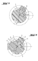
- the three impressions 5 are with respect to the Radialbezugsmasses R radially inwardly, which circumferentially alternately alternately adjacent to three radially outwardly formed forms 6 are assigned.
- Ic-Ic within the locking portion 3 are the three impressions. 5 arranged exactly at 0 °, 120 ° and 240 ° and form with the circumferentially alternating alternating forms 6 a threefold rotational symmetry as well Mirror symmetry off.
- Each expression 6 is exactly diametrically opposite one each Imprint 5 assigned.
- the impressions 5 and the expression 6 each extend axially over the entire locking area 3 of length V.
- a Radialbezugsmass R of the three impressions 5 accumulated central embossing angle ⁇ each 75 ° and a total of 225 °, as well as a Radialbezugsmass R of three versions 6 accumulated central embossment angle ⁇ each 45 ° and a total of 135 °.
- the ratio of both the sums and each of the central embossment angles ⁇ to the central embossment angle ⁇ thus gives a numerical value of 1.66.
- the ratio of a maximum embossing mass Xa and maximum embossing mass Xe determined with respect to the radial reference mass R gives a numerical value of 1.0 for each of the three embossings 5 and three embossments 6.
- the cross-sectional contour S of the indentations 5 is slightly concave, with their minimum radius of curvature K, the corresponds to the radius of the engaging locking ball 7, is greater than the sum of the maximum Ausmassungsmass Xa and the maximum embossing mass Xe, since the midpoint M of the maximum engaging locking ball 7 outside of the forms 6 radially outwardly limiting circumference U is.
- the ratio of the cross-sectional area Q formed in the cross-section Ic-Ic to a circular area ⁇ R 2 of the reference mass R is 0.95.
- the cross-sectional contour S has a concave bend 8.
- a cross-sectional contour S formed in cross-section Ic-Ic is a mathematically smooth, kink-free transition from the indentation 5 to the characteristic 6.
- An am Radial reference mass R of the three indentations 5 accumulated central embossing angle ⁇ each 77 ° and a total of 231 °, as well as on the Radialbezugsmass R of the three forms 6 accumulated central embossment angle ⁇ each 43 ° and a total of 129 °.
- the Ratio of both the sums and each of the central indentation angles ⁇ to the central pronouncement angle ⁇ thus gives a numerical value of 1.79.
- the relationship each determined with respect to the radial reference mass R maximum The degree of expression Xa and the maximum embossing mass Xe gives a numerical value of 1.0 for each of the three impressions 5 and three occurrences 6.
- the concave bend 8 is the Cross-sectional contour S within a leg-shaped embossment 5 with straight leg sections 9 arranged.
- Fig. 6 After the embodiment shown in Fig. 6 are two broad impressions 5 with a central embossing angle ⁇ of 55 ° and two narrow impressions. 5 with a central embossing angle ⁇ of 30 ° circumferentially distributed, the no have three-fold rotational symmetry and no mirror symmetry.
- One of the two Variants 6 is arranged between a narrow and a broad imprint 5, being between this expression 6 and the two circumferentially adjacent Indentations 5 an axially extending, cylindrical jacket-shaped guide surface 4c is formed with the radial reference mass R.
- the cross-sectional contour S points at Transition of the guide surface 4c to the expression 6 a concave bend 8 and to the Indentations 5 each have a convex kink 8.
Landscapes
- Engineering & Computer Science (AREA)
- Mechanical Engineering (AREA)
- Mining & Mineral Resources (AREA)
- Percussive Tools And Related Accessories (AREA)
- Processing Of Stones Or Stones Resemblance Materials (AREA)
- Devices For Opening Bottles Or Cans (AREA)
- Dental Tools And Instruments Or Auxiliary Dental Instruments (AREA)
- Road Repair (AREA)
- Adornments (AREA)
- Force Measurement Appropriate To Specific Purposes (AREA)
- Electrophonic Musical Instruments (AREA)
- Rotary Pumps (AREA)
- Earth Drilling (AREA)
Applications Claiming Priority (2)
| Application Number | Priority Date | Filing Date | Title |
|---|---|---|---|
| DE10338640 | 2003-08-22 | ||
| DE10338640A DE10338640A1 (de) | 2003-08-22 | 2003-08-22 | Einsteckende für ein drehendes und schlagendes Werkzeug |
Publications (3)
| Publication Number | Publication Date |
|---|---|
| EP1508391A2 true EP1508391A2 (fr) | 2005-02-23 |
| EP1508391A3 EP1508391A3 (fr) | 2007-12-05 |
| EP1508391B1 EP1508391B1 (fr) | 2009-12-16 |
Family
ID=34042246
Family Applications (1)
| Application Number | Title | Priority Date | Filing Date |
|---|---|---|---|
| EP04103985A Not-in-force EP1508391B1 (fr) | 2003-08-22 | 2004-08-19 | Tige pour un outil à percussion rotatif |
Country Status (10)
| Country | Link |
|---|---|
| US (1) | US7261169B2 (fr) |
| EP (1) | EP1508391B1 (fr) |
| JP (1) | JP4658539B2 (fr) |
| KR (1) | KR20050020600A (fr) |
| CN (1) | CN100381257C (fr) |
| AT (1) | ATE451991T1 (fr) |
| AU (1) | AU2004203611B2 (fr) |
| CA (1) | CA2476986A1 (fr) |
| DE (2) | DE10338640A1 (fr) |
| ZA (1) | ZA200406628B (fr) |
Cited By (4)
| Publication number | Priority date | Publication date | Assignee | Title |
|---|---|---|---|---|
| WO2009049953A1 (fr) * | 2007-10-10 | 2009-04-23 | Robert Bosch Gmbh | Système d'outil |
| EP1535704B1 (fr) * | 2003-11-26 | 2010-03-10 | HILTI Aktiengesellschaft | Porte-outil pour un outil rotatif à percussion |
| EP2612981A1 (fr) * | 2012-01-09 | 2013-07-10 | Sandvik Intellectual Property AB | Trépan pour un marteau à percussion, manche et patte de rétention correspondante |
| WO2016041662A1 (fr) * | 2014-09-16 | 2016-03-24 | Robert Bosch Gmbh | Outil de perçage |
Families Citing this family (13)
| Publication number | Priority date | Publication date | Assignee | Title |
|---|---|---|---|---|
| DE10227897A1 (de) * | 2002-06-21 | 2004-01-08 | Hilti Ag | Einsteckende und Werkzeugaufnahme für ein drehendes und schlagendes Werkzeug |
| GB2393931A (en) * | 2002-10-10 | 2004-04-14 | Black & Decker Inc | Tool for a rotary hammer |
| USD800907S1 (en) | 2015-03-25 | 2017-10-24 | Medtronic Ps Medical, Inc. | Surgical tool |
| US10080579B2 (en) | 2015-03-25 | 2018-09-25 | Medtronic Ps Medical, Inc. | Pin drive rotary surgical cutting tools and powered handpieces |
| USD800906S1 (en) | 2015-03-25 | 2017-10-24 | Medtronic Ps Medical, Inc. | Surgical tool |
| USD790699S1 (en) | 2015-03-25 | 2017-06-27 | Medtronic Ps Medical, Inc. | Surgical tool |
| USD782042S1 (en) | 2015-03-25 | 2017-03-21 | Medtronic Ps Medical, Inc. | Surgical tool |
| US10314610B2 (en) | 2015-03-25 | 2019-06-11 | Medtronic Ps Medical, Inc. | Slanted drive axis rotary surgical cutting tools and powered handpieces |
| USD800903S1 (en) | 2016-02-09 | 2017-10-24 | Medtronic Ps Medical, Inc. | Surgical tool |
| US10507568B2 (en) | 2016-12-15 | 2019-12-17 | Caterpillar Inc. | Hammer work tool having multi-position retention collar |
| US10849634B2 (en) | 2018-06-20 | 2020-12-01 | Medtronic Xomed, Inc. | Coupling portion for rotary surgical cutting systems |
| US11945087B2 (en) * | 2019-03-29 | 2024-04-02 | Tien-I Industrial Co., Ltd. | Impact tool head |
| US11305411B2 (en) * | 2019-09-23 | 2022-04-19 | Tien-I Industrial Co., Ltd. | Impact tool head assembling mechanism |
Citations (8)
| Publication number | Priority date | Publication date | Assignee | Title |
|---|---|---|---|---|
| US369248A (en) * | 1887-08-30 | Boring bit or drill | ||
| DE2405938A1 (de) * | 1974-02-08 | 1975-08-21 | Impex Essen Vertrieb | Werkzeughalterung fuer handschlaggeraete, insbesondere bohrhaemmer |
| DE3413432A1 (de) * | 1983-12-27 | 1985-07-04 | Gebrüder Heller GmbH Werkzeugfabrik, 2807 Achim | Bohrer fuer handbohrmaschinen |
| DE8433275U1 (de) * | 1984-11-14 | 1986-03-27 | Hawera Probst Gmbh + Co, 7980 Ravensburg | Bohrwerkzeug |
| DE4316799A1 (de) * | 1993-05-19 | 1994-07-14 | Fras Leonard Raphael Dipl El I | Gewindebohrer für Akkuschrauber |
| WO1997013602A2 (fr) * | 1995-10-12 | 1997-04-17 | Robert Bosch Gmbh | Outil inserable et porte-outil pour machines electriques a percer et/ou percutantes |
| DE19604283A1 (de) * | 1996-02-07 | 1997-08-14 | Bosch Gmbh Robert | Einsatzsystem für Maschinen mit Bohr- und/oder Schlagbetrieb |
| DE19604280A1 (de) * | 1996-02-07 | 1997-08-14 | Bosch Gmbh Robert | Einsatzsystem für Maschinen mit Bohr- und/oder Schlagbetrieb |
Family Cites Families (9)
| Publication number | Priority date | Publication date | Assignee | Title |
|---|---|---|---|---|
| DE3941646A1 (de) | 1989-12-16 | 1991-06-20 | Heller Werkzeug Gmbh Geb | Werkzeug zum schlagbohren und werkzeugaufnahme fuer schlagbohrende werkzeuge |
| DE4105414A1 (de) * | 1991-02-21 | 1992-08-27 | Hilti Ag | Werkzeug und werkzeughalter fuer handwerkzeuggeraete |
| DE4242452A1 (de) * | 1992-07-15 | 1994-01-20 | Hilti Ag | Werkzeug und Werkzeugaufnahme für Handwerkzeuggeräte |
| DE4223518A1 (de) * | 1992-07-17 | 1994-01-20 | Hilti Ag | Werkzeug und Werkzeugaufnahme für Handwerkzeuggeräte |
| DE4313578A1 (de) * | 1993-03-06 | 1994-09-08 | Hilti Ag | Werkzeug und Werkzeugaufnahme für Handwerkzeuggeräte |
| DE19516034A1 (de) * | 1995-05-04 | 1996-11-07 | Hilti Ag | Einrichtung zur Drehmomentübertragung bei Handwerkzeuggeräten |
| DE10057124A1 (de) * | 1999-11-17 | 2001-05-23 | Hawera Probst Gmbh | Meißel |
| DE10034742A1 (de) * | 2000-07-17 | 2002-01-31 | Hilti Ag | Werkzeug mit zugeordnetem Schlagwerkzeug |
| DE10102308A1 (de) * | 2001-01-19 | 2002-07-25 | Hilti Ag | Gesteinsbohrer mit Spülbohrung |
-
2003
- 2003-08-22 DE DE10338640A patent/DE10338640A1/de not_active Withdrawn
-
2004
- 2004-07-28 KR KR1020040059068A patent/KR20050020600A/ko not_active Application Discontinuation
- 2004-08-05 AU AU2004203611A patent/AU2004203611B2/en not_active Ceased
- 2004-08-10 CA CA002476986A patent/CA2476986A1/fr not_active Abandoned
- 2004-08-18 CN CNB2004100567850A patent/CN100381257C/zh not_active Expired - Fee Related
- 2004-08-19 EP EP04103985A patent/EP1508391B1/fr not_active Not-in-force
- 2004-08-19 AT AT04103985T patent/ATE451991T1/de not_active IP Right Cessation
- 2004-08-19 ZA ZA200406628A patent/ZA200406628B/xx unknown
- 2004-08-19 DE DE502004010510T patent/DE502004010510D1/de active Active
- 2004-08-20 US US10/922,551 patent/US7261169B2/en active Active
- 2004-08-20 JP JP2004241447A patent/JP4658539B2/ja not_active Expired - Fee Related
Patent Citations (8)
| Publication number | Priority date | Publication date | Assignee | Title |
|---|---|---|---|---|
| US369248A (en) * | 1887-08-30 | Boring bit or drill | ||
| DE2405938A1 (de) * | 1974-02-08 | 1975-08-21 | Impex Essen Vertrieb | Werkzeughalterung fuer handschlaggeraete, insbesondere bohrhaemmer |
| DE3413432A1 (de) * | 1983-12-27 | 1985-07-04 | Gebrüder Heller GmbH Werkzeugfabrik, 2807 Achim | Bohrer fuer handbohrmaschinen |
| DE8433275U1 (de) * | 1984-11-14 | 1986-03-27 | Hawera Probst Gmbh + Co, 7980 Ravensburg | Bohrwerkzeug |
| DE4316799A1 (de) * | 1993-05-19 | 1994-07-14 | Fras Leonard Raphael Dipl El I | Gewindebohrer für Akkuschrauber |
| WO1997013602A2 (fr) * | 1995-10-12 | 1997-04-17 | Robert Bosch Gmbh | Outil inserable et porte-outil pour machines electriques a percer et/ou percutantes |
| DE19604283A1 (de) * | 1996-02-07 | 1997-08-14 | Bosch Gmbh Robert | Einsatzsystem für Maschinen mit Bohr- und/oder Schlagbetrieb |
| DE19604280A1 (de) * | 1996-02-07 | 1997-08-14 | Bosch Gmbh Robert | Einsatzsystem für Maschinen mit Bohr- und/oder Schlagbetrieb |
Cited By (9)
| Publication number | Priority date | Publication date | Assignee | Title |
|---|---|---|---|---|
| EP1535704B1 (fr) * | 2003-11-26 | 2010-03-10 | HILTI Aktiengesellschaft | Porte-outil pour un outil rotatif à percussion |
| WO2009049953A1 (fr) * | 2007-10-10 | 2009-04-23 | Robert Bosch Gmbh | Système d'outil |
| CN101821041B (zh) * | 2007-10-10 | 2013-05-29 | 罗伯特·博世有限公司 | 刀具系统 |
| EP2612981A1 (fr) * | 2012-01-09 | 2013-07-10 | Sandvik Intellectual Property AB | Trépan pour un marteau à percussion, manche et patte de rétention correspondante |
| WO2013104470A3 (fr) * | 2012-01-09 | 2014-01-03 | Sandvik Intellectual Property Ab | Trépan pour marteau à percussion, et queue associée |
| CN104080997A (zh) * | 2012-01-09 | 2014-10-01 | 山特维克知识产权股份有限公司 | 冲击锤的钻头及用于钻头的钻柄 |
| CN104080997B (zh) * | 2012-01-09 | 2017-04-26 | 山特维克知识产权股份有限公司 | 冲击锤的钻头及用于钻头的钻柄 |
| US9719306B2 (en) | 2012-01-09 | 2017-08-01 | Sandvik Intellectual Property Ab | Drill bit for a percussive hammer and shank therefore |
| WO2016041662A1 (fr) * | 2014-09-16 | 2016-03-24 | Robert Bosch Gmbh | Outil de perçage |
Also Published As
| Publication number | Publication date |
|---|---|
| US20050072600A1 (en) | 2005-04-07 |
| EP1508391B1 (fr) | 2009-12-16 |
| CN100381257C (zh) | 2008-04-16 |
| ZA200406628B (en) | 2005-06-14 |
| JP4658539B2 (ja) | 2011-03-23 |
| AU2004203611B2 (en) | 2009-05-28 |
| CA2476986A1 (fr) | 2005-02-22 |
| EP1508391A3 (fr) | 2007-12-05 |
| JP2005066821A (ja) | 2005-03-17 |
| US7261169B2 (en) | 2007-08-28 |
| AU2004203611A1 (en) | 2005-03-10 |
| DE10338640A1 (de) | 2005-03-17 |
| DE502004010510D1 (de) | 2010-01-28 |
| CN1583369A (zh) | 2005-02-23 |
| ATE451991T1 (de) | 2010-01-15 |
| KR20050020600A (ko) | 2005-03-04 |
Similar Documents
| Publication | Publication Date | Title |
|---|---|---|
| EP1508391B1 (fr) | Tige pour un outil à percussion rotatif | |
| EP1174225B1 (fr) | Outill de percussion | |
| EP1602452B1 (fr) | Tige pour un outil rotatif et/ou à percussion | |
| EP0854773B1 (fr) | Outil inserable et porte-outil pour machines electriques a percer et/ou percutantes | |
| EP0880426B1 (fr) | Porte-outil pour outils d'insertion sur machines travaillant par perforation et/ou percussion | |
| DE19521993B4 (de) | Werkzeughalter und Werkzeug für eine Bohr- und/oder Schlagwerkzeugmaschine | |
| EP2628572B1 (fr) | Burin | |
| DE4340726C1 (de) | Einrichtung an Handwerkzeugmaschinen zur Drehmitnahme von Werkzeugen | |
| DE3824894A1 (de) | Einrichtung an handwerkzeugmaschinen zur drehmomentuebertragung | |
| EP0605602B1 (fr) | Dispositif monte sur des outils a main mecaniques | |
| DE102011085187B3 (de) | Bohrer und Herstellungsverfahren für einen Bohrer | |
| WO2016119988A1 (fr) | Dispositif à percussion, en particulier pour clé à chocs | |
| DE4141846A1 (de) | Werkzeug zum schlagbohren und meisseln und werkzeugaufnahme fuer diese werkzeuge | |
| EP0739266A1 (fr) | Dispositif d'entrainement en rotation d'outils pour machines-outils manuelles | |
| DE10357380A1 (de) | Einsteckende für ein drehendes und/oder schlagendes Werkzeug | |
| EP2519372A1 (fr) | Outil perforateur de roche pour la perforation roto-percutante de béton, de roche, de maçonnerie et de matériaux équivalents | |
| DE2343353C2 (de) | Motorisch angetriebene Schlagbohrmaschine, welche wahlweise für Schlagbohrbetrieb, Nur-Bohrbetrieb oder Nur-Schlagbetrieb einstellbar ist | |
| CH695219A5 (de) | Gesteinsbohrer mit Spülbohrung. | |
| EP1375078A1 (fr) | Adaptateur de tiges et porte-outil pour un outil à percussion | |
| EP2007554A1 (fr) | Outil rotatif amovible pour une machine-outil à main | |
| EP1273396B1 (fr) | Ciseau resp. forêt | |
| DE19700754A1 (de) | Handwerkzeugmaschine | |
| DE10353283A1 (de) | Werkzeugaufnahme für einen Bohrhammer | |
| DE8433275U1 (de) | Bohrwerkzeug | |
| DE4317273A1 (de) | Werkzeugaufnahme für Handbohr- und Schlaggeräte mit SDS-Zusatznut |
Legal Events
| Date | Code | Title | Description |
|---|---|---|---|
| PUAI | Public reference made under article 153(3) epc to a published international application that has entered the european phase |
Free format text: ORIGINAL CODE: 0009012 |
|
| AK | Designated contracting states |
Kind code of ref document: A2 Designated state(s): AT BE BG CH CY CZ DE DK EE ES FI FR GB GR HU IE IT LI LU MC NL PL PT RO SE SI SK TR |
|
| AX | Request for extension of the european patent |
Extension state: AL HR LT LV MK |
|
| PUAL | Search report despatched |
Free format text: ORIGINAL CODE: 0009013 |
|
| AK | Designated contracting states |
Kind code of ref document: A3 Designated state(s): AT BE BG CH CY CZ DE DK EE ES FI FR GB GR HU IE IT LI LU MC NL PL PT RO SE SI SK TR |
|
| AX | Request for extension of the european patent |
Extension state: AL HR LT LV MK |
|
| 17P | Request for examination filed |
Effective date: 20080605 |
|
| AKX | Designation fees paid |
Designated state(s): AT BE BG CH CY CZ DE DK EE ES FI FR GB GR HU IE IT LI LU MC NL PL PT RO SE SI SK TR |
|
| 17Q | First examination report despatched |
Effective date: 20080819 |
|
| GRAP | Despatch of communication of intention to grant a patent |
Free format text: ORIGINAL CODE: EPIDOSNIGR1 |
|
| GRAS | Grant fee paid |
Free format text: ORIGINAL CODE: EPIDOSNIGR3 |
|
| GRAA | (expected) grant |
Free format text: ORIGINAL CODE: 0009210 |
|
| AK | Designated contracting states |
Kind code of ref document: B1 Designated state(s): AT BE BG CH CY CZ DE DK EE ES FI FR GB GR HU IE IT LI LU MC NL PL PT RO SE SI SK TR |
|
| REG | Reference to a national code |
Ref country code: GB Ref legal event code: FG4D Free format text: NOT ENGLISH |
|
| REG | Reference to a national code |
Ref country code: CH Ref legal event code: EP |
|
| REG | Reference to a national code |
Ref country code: IE Ref legal event code: FG4D |
|
| REF | Corresponds to: |
Ref document number: 502004010510 Country of ref document: DE Date of ref document: 20100128 Kind code of ref document: P |
|
| REG | Reference to a national code |
Ref country code: NL Ref legal event code: VDEP Effective date: 20091216 |
|
| PG25 | Lapsed in a contracting state [announced via postgrant information from national office to epo] |
Ref country code: SE Free format text: LAPSE BECAUSE OF FAILURE TO SUBMIT A TRANSLATION OF THE DESCRIPTION OR TO PAY THE FEE WITHIN THE PRESCRIBED TIME-LIMIT Effective date: 20091216 Ref country code: FI Free format text: LAPSE BECAUSE OF FAILURE TO SUBMIT A TRANSLATION OF THE DESCRIPTION OR TO PAY THE FEE WITHIN THE PRESCRIBED TIME-LIMIT Effective date: 20091216 |
|
| PG25 | Lapsed in a contracting state [announced via postgrant information from national office to epo] |
Ref country code: SI Free format text: LAPSE BECAUSE OF FAILURE TO SUBMIT A TRANSLATION OF THE DESCRIPTION OR TO PAY THE FEE WITHIN THE PRESCRIBED TIME-LIMIT Effective date: 20091216 Ref country code: PL Free format text: LAPSE BECAUSE OF FAILURE TO SUBMIT A TRANSLATION OF THE DESCRIPTION OR TO PAY THE FEE WITHIN THE PRESCRIBED TIME-LIMIT Effective date: 20091216 |
|
| REG | Reference to a national code |
Ref country code: IE Ref legal event code: FD4D |
|
| PG25 | Lapsed in a contracting state [announced via postgrant information from national office to epo] |
Ref country code: PT Free format text: LAPSE BECAUSE OF FAILURE TO SUBMIT A TRANSLATION OF THE DESCRIPTION OR TO PAY THE FEE WITHIN THE PRESCRIBED TIME-LIMIT Effective date: 20100416 Ref country code: IE Free format text: LAPSE BECAUSE OF FAILURE TO SUBMIT A TRANSLATION OF THE DESCRIPTION OR TO PAY THE FEE WITHIN THE PRESCRIBED TIME-LIMIT Effective date: 20091216 Ref country code: ES Free format text: LAPSE BECAUSE OF FAILURE TO SUBMIT A TRANSLATION OF THE DESCRIPTION OR TO PAY THE FEE WITHIN THE PRESCRIBED TIME-LIMIT Effective date: 20100327 Ref country code: BG Free format text: LAPSE BECAUSE OF FAILURE TO SUBMIT A TRANSLATION OF THE DESCRIPTION OR TO PAY THE FEE WITHIN THE PRESCRIBED TIME-LIMIT Effective date: 20100316 Ref country code: EE Free format text: LAPSE BECAUSE OF FAILURE TO SUBMIT A TRANSLATION OF THE DESCRIPTION OR TO PAY THE FEE WITHIN THE PRESCRIBED TIME-LIMIT Effective date: 20091216 Ref country code: NL Free format text: LAPSE BECAUSE OF FAILURE TO SUBMIT A TRANSLATION OF THE DESCRIPTION OR TO PAY THE FEE WITHIN THE PRESCRIBED TIME-LIMIT Effective date: 20091216 Ref country code: RO Free format text: LAPSE BECAUSE OF FAILURE TO SUBMIT A TRANSLATION OF THE DESCRIPTION OR TO PAY THE FEE WITHIN THE PRESCRIBED TIME-LIMIT Effective date: 20091216 |
|
| PG25 | Lapsed in a contracting state [announced via postgrant information from national office to epo] |
Ref country code: SK Free format text: LAPSE BECAUSE OF FAILURE TO SUBMIT A TRANSLATION OF THE DESCRIPTION OR TO PAY THE FEE WITHIN THE PRESCRIBED TIME-LIMIT Effective date: 20091216 Ref country code: CZ Free format text: LAPSE BECAUSE OF FAILURE TO SUBMIT A TRANSLATION OF THE DESCRIPTION OR TO PAY THE FEE WITHIN THE PRESCRIBED TIME-LIMIT Effective date: 20091216 |
|
| PLBE | No opposition filed within time limit |
Free format text: ORIGINAL CODE: 0009261 |
|
| STAA | Information on the status of an ep patent application or granted ep patent |
Free format text: STATUS: NO OPPOSITION FILED WITHIN TIME LIMIT |
|
| PG25 | Lapsed in a contracting state [announced via postgrant information from national office to epo] |
Ref country code: GR Free format text: LAPSE BECAUSE OF FAILURE TO SUBMIT A TRANSLATION OF THE DESCRIPTION OR TO PAY THE FEE WITHIN THE PRESCRIBED TIME-LIMIT Effective date: 20100317 Ref country code: CY Free format text: LAPSE BECAUSE OF FAILURE TO SUBMIT A TRANSLATION OF THE DESCRIPTION OR TO PAY THE FEE WITHIN THE PRESCRIBED TIME-LIMIT Effective date: 20091216 |
|
| 26N | No opposition filed |
Effective date: 20100917 |
|
| PG25 | Lapsed in a contracting state [announced via postgrant information from national office to epo] |
Ref country code: DK Free format text: LAPSE BECAUSE OF FAILURE TO SUBMIT A TRANSLATION OF THE DESCRIPTION OR TO PAY THE FEE WITHIN THE PRESCRIBED TIME-LIMIT Effective date: 20091216 |
|
| BERE | Be: lapsed |
Owner name: HILTI AKTIENGESELLSCHAFT Effective date: 20100831 |
|
| PG25 | Lapsed in a contracting state [announced via postgrant information from national office to epo] |
Ref country code: IT Free format text: LAPSE BECAUSE OF FAILURE TO SUBMIT A TRANSLATION OF THE DESCRIPTION OR TO PAY THE FEE WITHIN THE PRESCRIBED TIME-LIMIT Effective date: 20091216 Ref country code: MC Free format text: LAPSE BECAUSE OF NON-PAYMENT OF DUE FEES Effective date: 20100831 |
|
| REG | Reference to a national code |
Ref country code: CH Ref legal event code: PL |
|
| PG25 | Lapsed in a contracting state [announced via postgrant information from national office to epo] |
Ref country code: CH Free format text: LAPSE BECAUSE OF NON-PAYMENT OF DUE FEES Effective date: 20100831 Ref country code: LI Free format text: LAPSE BECAUSE OF NON-PAYMENT OF DUE FEES Effective date: 20100831 |
|
| PG25 | Lapsed in a contracting state [announced via postgrant information from national office to epo] |
Ref country code: BE Free format text: LAPSE BECAUSE OF NON-PAYMENT OF DUE FEES Effective date: 20100831 |
|
| PG25 | Lapsed in a contracting state [announced via postgrant information from national office to epo] |
Ref country code: AT Free format text: LAPSE BECAUSE OF NON-PAYMENT OF DUE FEES Effective date: 20100819 |
|
| PG25 | Lapsed in a contracting state [announced via postgrant information from national office to epo] |
Ref country code: LU Free format text: LAPSE BECAUSE OF NON-PAYMENT OF DUE FEES Effective date: 20100819 Ref country code: HU Free format text: LAPSE BECAUSE OF FAILURE TO SUBMIT A TRANSLATION OF THE DESCRIPTION OR TO PAY THE FEE WITHIN THE PRESCRIBED TIME-LIMIT Effective date: 20100617 |
|
| PG25 | Lapsed in a contracting state [announced via postgrant information from national office to epo] |
Ref country code: TR Free format text: LAPSE BECAUSE OF FAILURE TO SUBMIT A TRANSLATION OF THE DESCRIPTION OR TO PAY THE FEE WITHIN THE PRESCRIBED TIME-LIMIT Effective date: 20091216 |
|
| REG | Reference to a national code |
Ref country code: FR Ref legal event code: PLFP Year of fee payment: 13 |
|
| REG | Reference to a national code |
Ref country code: FR Ref legal event code: PLFP Year of fee payment: 14 |
|
| REG | Reference to a national code |
Ref country code: FR Ref legal event code: PLFP Year of fee payment: 15 |
|
| PGFP | Annual fee paid to national office [announced via postgrant information from national office to epo] |
Ref country code: FR Payment date: 20180827 Year of fee payment: 15 Ref country code: DE Payment date: 20180823 Year of fee payment: 15 |
|
| PGFP | Annual fee paid to national office [announced via postgrant information from national office to epo] |
Ref country code: GB Payment date: 20180822 Year of fee payment: 15 |
|
| REG | Reference to a national code |
Ref country code: DE Ref legal event code: R119 Ref document number: 502004010510 Country of ref document: DE |
|
| GBPC | Gb: european patent ceased through non-payment of renewal fee |
Effective date: 20190819 |
|
| PG25 | Lapsed in a contracting state [announced via postgrant information from national office to epo] |
Ref country code: FR Free format text: LAPSE BECAUSE OF NON-PAYMENT OF DUE FEES Effective date: 20190831 Ref country code: DE Free format text: LAPSE BECAUSE OF NON-PAYMENT OF DUE FEES Effective date: 20200303 |
|
| PG25 | Lapsed in a contracting state [announced via postgrant information from national office to epo] |
Ref country code: GB Free format text: LAPSE BECAUSE OF NON-PAYMENT OF DUE FEES Effective date: 20190819 |