EP1508391A2 - Shank for a rotary percussion tool - Google Patents
Shank for a rotary percussion tool Download PDFInfo
- Publication number
- EP1508391A2 EP1508391A2 EP04103985A EP04103985A EP1508391A2 EP 1508391 A2 EP1508391 A2 EP 1508391A2 EP 04103985 A EP04103985 A EP 04103985A EP 04103985 A EP04103985 A EP 04103985A EP 1508391 A2 EP1508391 A2 EP 1508391A2
- Authority
- EP
- European Patent Office
- Prior art keywords
- end according
- insertion end
- indentations
- cross
- optionally
- Prior art date
- Legal status (The legal status is an assumption and is not a legal conclusion. Google has not performed a legal analysis and makes no representation as to the accuracy of the status listed.)
- Granted
Links
Images


Classifications
-
- B—PERFORMING OPERATIONS; TRANSPORTING
- B23—MACHINE TOOLS; METAL-WORKING NOT OTHERWISE PROVIDED FOR
- B23B—TURNING; BORING
- B23B51/00—Tools for drilling machines
- B23B51/02—Twist drills
-
- B—PERFORMING OPERATIONS; TRANSPORTING
- B25—HAND TOOLS; PORTABLE POWER-DRIVEN TOOLS; MANIPULATORS
- B25D—PERCUSSIVE TOOLS
- B25D17/00—Details of, or accessories for, portable power-driven percussive tools
- B25D17/08—Means for retaining and guiding the tool bit, e.g. chucks allowing axial oscillation of the tool bit
- B25D17/084—Rotating chucks or sockets
- B25D17/088—Rotating chucks or sockets with radial movable locking elements co-operating with bit shafts specially adapted therefor
-
- B—PERFORMING OPERATIONS; TRANSPORTING
- B23—MACHINE TOOLS; METAL-WORKING NOT OTHERWISE PROVIDED FOR
- B23B—TURNING; BORING
- B23B31/00—Chucks; Expansion mandrels; Adaptations thereof for remote control
- B23B31/005—Cylindrical shanks of tools
-
- B—PERFORMING OPERATIONS; TRANSPORTING
- B23—MACHINE TOOLS; METAL-WORKING NOT OTHERWISE PROVIDED FOR
- B23B—TURNING; BORING
- B23B45/00—Hand-held or like portable drilling machines, e.g. drill guns; Equipment therefor
-
- B—PERFORMING OPERATIONS; TRANSPORTING
- B28—WORKING CEMENT, CLAY, OR STONE
- B28D—WORKING STONE OR STONE-LIKE MATERIALS
- B28D1/00—Working stone or stone-like materials, e.g. brick, concrete or glass, not provided for elsewhere; Machines, devices, tools therefor
- B28D1/14—Working stone or stone-like materials, e.g. brick, concrete or glass, not provided for elsewhere; Machines, devices, tools therefor by boring or drilling
-
- B—PERFORMING OPERATIONS; TRANSPORTING
- B23—MACHINE TOOLS; METAL-WORKING NOT OTHERWISE PROVIDED FOR
- B23B—TURNING; BORING
- B23B2231/00—Details of chucks, toolholder shanks or tool shanks
- B23B2231/02—Features of shanks of tools not relating to the operation performed by the tool
- B23B2231/026—Grooves
- B23B2231/0264—Axial grooves
-
- B—PERFORMING OPERATIONS; TRANSPORTING
- B23—MACHINE TOOLS; METAL-WORKING NOT OTHERWISE PROVIDED FOR
- B23B—TURNING; BORING
- B23B2231/00—Details of chucks, toolholder shanks or tool shanks
- B23B2231/02—Features of shanks of tools not relating to the operation performed by the tool
- B23B2231/028—Lugs
-
- Y—GENERAL TAGGING OF NEW TECHNOLOGICAL DEVELOPMENTS; GENERAL TAGGING OF CROSS-SECTIONAL TECHNOLOGIES SPANNING OVER SEVERAL SECTIONS OF THE IPC; TECHNICAL SUBJECTS COVERED BY FORMER USPC CROSS-REFERENCE ART COLLECTIONS [XRACs] AND DIGESTS
- Y10—TECHNICAL SUBJECTS COVERED BY FORMER USPC
- Y10T—TECHNICAL SUBJECTS COVERED BY FORMER US CLASSIFICATION
- Y10T408/00—Cutting by use of rotating axially moving tool
- Y10T408/89—Tool or Tool with support
- Y10T408/907—Tool or Tool with support including detailed shank
Definitions
- the invention refers to an insertion end for an at least partially rotating and / or striking tool, such as a drill bit, chisel or cutting bit Machining of rock, concrete or masonry.
- DE3941646A1 shows an insertion end extending along an axis, cylinder jacket-shaped guide surfaces and axially towards the free front end Locking grooves and axially open rotary drive grooves, wherein radially displaceable Locking body of the associated tool holder in the locking grooves engage and limit the axial mobility of the tool.
- another insertion end has three additional, up to the free end extending, circumferentially arranged between grooves webs.
- the with respect to the diameter of the cylinder jacket-shaped guide surfaces radially inward lying rotary driving surfaces require high due to their small radial center distance Contact surface pressure for torque transmission, making this fast wear out.
- the insertion end becomes axially the cross-sectional area available for the impact transmission diminished, causing disturbing reflections that impulse transmission deteriorate.
- the insertion end according to DE3413432A1 has three circumferentially symmetrically distributed, axially on both sides closed grooves, which by forming non-cutting radially into a wire blank were embossed and form at the tangential groove edge radial elevations, whereby the effective for rotational drive outer diameter of the insertion end something can be enlarged, in the form of special guide surfaces for receiving Inserting different diameter serves in a special three-jaw chuck. There the guide surfaces exclusively by the formed on the tangential Nutenrand Elevations are formed, these are for a highly weary transmission high torques unsuitable.
- the spigot according to DE8433275U1 has three circumferentially symmetrically distributed, axially on both sides closed grooves, the non-cutting by forming into a wire blank radially were embossed and form radial shapes.
- the central impression angle is always smaller than the central embossing angle.
- the object of the present invention is to realize a male end for a rotating and / or beating tool, which high torques can transmit low-wear and has a good impulse response.
- Another Aspect consists in the time- and material-efficient production of male ends.
- an insertion end of an at least partially rotating along an axis and / or impact driven tool is a constant, at least partially along the axis extending Radialbezugsmass, wherein within a locking area in a cross-section to the axis of at least three, at least at 0 °, 120 ° and 240 ° within formed the radial reference mass impressions, of which at least one axially to is closed at the free end, and outside the Radialbezugsmasses at least one, circumferentially arranged between two adjacent impressions, expression is present, wherein a cross-section on Radialbezugsmass the indentations accumulated central embossing angle totaling at least 150 °, as well as an im Cross-section on Radialbezugsmass the characteristics accumulated central The total degree of embossment is less than 150 ° and that of the sum difference at least 15 °.
- the central Ausgargungswinkel is, in one of a wire blank of the Radialbezugsmasses at least partially reshaped locking area by the In this case, the material displaced with respect to one each with the inverse radius weighted Radial imprinting measure in the circumferential mean a larger radial Expressive effect causes, which in a torque transmission to the tool by means of a radially outer attacking on the expression, one-sided tangential constraint to lower contact surface pressures and thus to much less wear on Infectious leads.
- the central embossing angle of the at least three impressions each more than 60 °, whereby in each of these impressions a radially engaging Locking element, in particular a locking ball, a tool holder can engage sufficiently deep for axial locking.
- the ratio gives the sum of the central embossment angle to the sum the central pronouncement angle has a numerical value in the range of 1.2 to 2.0, further advantageous with respect to each embossing angle and the at least three embossing angles, whereby one, with a minimum radius of curvature of at least the sum of the maximum degree of expression and maximum embossing, only slightly concave curved cross-sectional contour of the indentation is formed, which with respect to a Alternating stress of the expression in the torque transmission a small Notch number represents and thus avoids material fatigue in Kerbground.
- the ratio of each results with respect to the radial reference mass certain maximum degree of expression and maximum embossing one Numerical value in the range of 0.65 to 1.20, optional with respect to each of the at least three Indentations, whereby at such a cross-sectional contour a sufficiently large, for the impact pulse transmission remains essential, axially inner core diameter.
- the ratio of the cross-sectional area to a circular area of the Reference mass in the range of 0.9 to 1.0, whereby the cross-sectional area of one of a Wire blank of Radialbezugsmasses at least partially reshaped Locking area along the insertion end remains approximately the same and thus power-reducing, leading to reflections of the shock wave, acoustic impedance jumps be avoided.
- the cross-sectional contour forms a smooth transition from the impression to Characteristic, which predestined attachment points for abrasive dust accumulation or wear-effective local pressure points for the associated tool holder be avoided.
- axially extending Guide surfaces available, which are optionally formed cylinder jacket-shaped, whereby a high axial bending moment can be transmitted to the tool with little wear.
- a good concentricity of the tool is achieved.
- the axial length of a guide surface arranged towards the free end at least 1.0 times the Radialbezugsmasses, whereby at the free end also at axial impact load a sufficient axial sealing surface is available.
- each further advantageous one expression diametrically per one impression is arranged opposite, whereby by means of a hand ergonomic favorable +/- 60 ° Twisting the tool always an insertion into an associated tool holder is possible.
- each individual form has an embossing angle of less than 50 °, whereby a permitted for torque transmission Verschleissmass first on Einsteckende by the constructive narrow over the Ausgargungswinkel Expressions is exceeded, the tangential contact surface pressures in the Tool holder subject, instead of the assigned wide Torque transmission means a durable as possible tool holder.
- the indentations and the expression extend axially over the entire Locking area, whereby the displaced during the forming of the impressions Material substantially radially in the expression fliest.
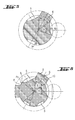
- FIGS. 1 a, 1 bund 1 c has one along an axis A rotating and hitting driven tool 1 in the form of a drill or chisel to the free end Einsteckende 2 with a Radialbezugsmass R and an axial locking portion. 3 on.
- Axial on both sides of the locking area 3 are two cylinder jacket-shaped Guide surfaces 4a, 4b arranged, which along the axis A with constant Radialbezugsmass R extend and three within the axial locking portion. 3 trained indentations 5 each axially close on both sides.
- the to the free end of the Inserting 2 arranged towards the guide surface 4a has an axial length F, which is the is twice the radial reference mass R.
- the three impressions 5 are with respect to the Radialbezugsmasses R radially inwardly, which circumferentially alternately alternately adjacent to three radially outwardly formed forms 6 are assigned.
- Ic-Ic within the locking portion 3 are the three impressions. 5 arranged exactly at 0 °, 120 ° and 240 ° and form with the circumferentially alternating alternating forms 6 a threefold rotational symmetry as well Mirror symmetry off.
- Each expression 6 is exactly diametrically opposite one each Imprint 5 assigned.
- the impressions 5 and the expression 6 each extend axially over the entire locking area 3 of length V.
- a Radialbezugsmass R of the three impressions 5 accumulated central embossing angle ⁇ each 75 ° and a total of 225 °, as well as a Radialbezugsmass R of three versions 6 accumulated central embossment angle ⁇ each 45 ° and a total of 135 °.
- the ratio of both the sums and each of the central embossment angles ⁇ to the central embossment angle ⁇ thus gives a numerical value of 1.66.
- the ratio of a maximum embossing mass Xa and maximum embossing mass Xe determined with respect to the radial reference mass R gives a numerical value of 1.0 for each of the three embossings 5 and three embossments 6.
- the cross-sectional contour S of the indentations 5 is slightly concave, with their minimum radius of curvature K, the corresponds to the radius of the engaging locking ball 7, is greater than the sum of the maximum Ausmassungsmass Xa and the maximum embossing mass Xe, since the midpoint M of the maximum engaging locking ball 7 outside of the forms 6 radially outwardly limiting circumference U is.
- the ratio of the cross-sectional area Q formed in the cross-section Ic-Ic to a circular area ⁇ R 2 of the reference mass R is 0.95.
- the cross-sectional contour S has a concave bend 8.
- a cross-sectional contour S formed in cross-section Ic-Ic is a mathematically smooth, kink-free transition from the indentation 5 to the characteristic 6.
- An am Radial reference mass R of the three indentations 5 accumulated central embossing angle ⁇ each 77 ° and a total of 231 °, as well as on the Radialbezugsmass R of the three forms 6 accumulated central embossment angle ⁇ each 43 ° and a total of 129 °.
- the Ratio of both the sums and each of the central indentation angles ⁇ to the central pronouncement angle ⁇ thus gives a numerical value of 1.79.
- the relationship each determined with respect to the radial reference mass R maximum The degree of expression Xa and the maximum embossing mass Xe gives a numerical value of 1.0 for each of the three impressions 5 and three occurrences 6.
- the concave bend 8 is the Cross-sectional contour S within a leg-shaped embossment 5 with straight leg sections 9 arranged.
- Fig. 6 After the embodiment shown in Fig. 6 are two broad impressions 5 with a central embossing angle ⁇ of 55 ° and two narrow impressions. 5 with a central embossing angle ⁇ of 30 ° circumferentially distributed, the no have three-fold rotational symmetry and no mirror symmetry.
- One of the two Variants 6 is arranged between a narrow and a broad imprint 5, being between this expression 6 and the two circumferentially adjacent Indentations 5 an axially extending, cylindrical jacket-shaped guide surface 4c is formed with the radial reference mass R.
- the cross-sectional contour S points at Transition of the guide surface 4c to the expression 6 a concave bend 8 and to the Indentations 5 each have a convex kink 8.
Landscapes
- Engineering & Computer Science (AREA)
- Mechanical Engineering (AREA)
- Mining & Mineral Resources (AREA)
- Percussive Tools And Related Accessories (AREA)
- Processing Of Stones Or Stones Resemblance Materials (AREA)
- Devices For Opening Bottles Or Cans (AREA)
- Dental Tools And Instruments Or Auxiliary Dental Instruments (AREA)
- Road Repair (AREA)
- Adornments (AREA)
- Force Measurement Appropriate To Specific Purposes (AREA)
- Electrophonic Musical Instruments (AREA)
- Rotary Pumps (AREA)
- Earth Drilling (AREA)
Abstract
Description
Die Erfindung bezeichnet ein Einsteckende für ein zumindest teilweise drehendes und/oder schlagendes Werkzeug, wie einen Bohrmeissel, Meissel oder Schneidbohrkrone zur Bearbeitung von Gestein, Beton oder Mauerwerk.The invention refers to an insertion end for an at least partially rotating and / or striking tool, such as a drill bit, chisel or cutting bit Machining of rock, concrete or masonry.
Üblicherweise weist ein drehendes und schlagendes Werkzeug beispielsweise entsprechend DE3941646A1 ein sich längs einer Achse erstreckendes Einsteckende, zylindermantelförmige Führungsflächen und zum freien Stirnende hin axial geschlossene Verriegelungsnuten und axial offene Drehmitnahmenuten auf, wobei radial versetzbare Verriegelungskörper der zugeordneten Werkzeugaufnahme in die Verriegelungsnuten eingreifen und die axiale Beweglichkeit des Werkzeugs begrenzen.Usually, a rotating and beating tool, for example, accordingly DE3941646A1 shows an insertion end extending along an axis, cylinder jacket-shaped guide surfaces and axially towards the free front end Locking grooves and axially open rotary drive grooves, wherein radially displaceable Locking body of the associated tool holder in the locking grooves engage and limit the axial mobility of the tool.
Nach der DE19604283A1 weist ein weiteres Einsteckende drei zusätzliche, sich bis zum freien Stirnende erstreckende, umfänglich zwischen Nuten angeordnete Stege auf. Die bezüglich des Durchmessers der zylindermantelförmigen Führungsflächen radial innen liegenden Drehmitnahmeflächen benötigen durch ihren geringen radialen Achsabstand hohe Kontaktflächenpressungen zur Drehmomentübertragung, wodurch diese schnell verschleissen. Durch eine spanende Einbringung derartiger Nuten in das zuvor runde Einsteckende wird zudem axial die für die Schlagübertragung verfügbare Querschnittsfläche vermindert, wodurch störende Reflexionen auftreten, die die Impulsübertragung verschlechtern.According to DE19604283A1, another insertion end has three additional, up to the free end extending, circumferentially arranged between grooves webs. The with respect to the diameter of the cylinder jacket-shaped guide surfaces radially inward lying rotary driving surfaces require high due to their small radial center distance Contact surface pressure for torque transmission, making this fast wear out. By a cutting introduction of such grooves in the previously round In addition, the insertion end becomes axially the cross-sectional area available for the impact transmission diminished, causing disturbing reflections that impulse transmission deteriorate.
Das Einsteckende nach der DE3413432A1 weist drei umfänglich symmetrisch verteilte, axial beidseitig geschlossene Nuten auf, die durch Umformen spanlos radial in einen Drahtrohling eingeprägt wurden und am tangentialen Nutenrand radiale Überhöhungen ausformen, wodurch der zur Drehmitnahme wirksame Aussendurchmesser des Einsteckendes etwas vergrössert werden kann, der in Form spezieller Führungsflächen zur Aufnahme von Einsteckenden unterschiedlichen Durchmessers in ein spezielles Dreibackenfutter dient. Da die Führungsflächen ausschliesslich durch die am tangentialen Nutenrand ausgebildeten Überhöhungen ausgebildet werden, sind diese für eine stark verschleissende Übertragung hoher Drehmomente ungeeignet. The insertion end according to DE3413432A1 has three circumferentially symmetrically distributed, axially on both sides closed grooves, which by forming non-cutting radially into a wire blank were embossed and form at the tangential groove edge radial elevations, whereby the effective for rotational drive outer diameter of the insertion end something can be enlarged, in the form of special guide surfaces for receiving Inserting different diameter serves in a special three-jaw chuck. There the guide surfaces exclusively by the formed on the tangential Nutenrand Elevations are formed, these are for a highly weary transmission high torques unsuitable.
Das Einsteckende nach der DE8433275U1 weist drei umfänglich symmetrisch verteilte, axial beidseitig geschlossene Nuten auf, die durch Umformen spanlos in einen Drahtrohling radial eingeprägt wurden und radiale Ausprägungen ausformen. Der zentrale Einprägewinkel ist dabei stets kleiner gleich dem zentralen Ausprägewinkel. Mit geeigneten, eine Längenausdehnung des Drahtrohlings beim Umformen unterbindenden, Umformwerkzeugen wird eine querschnittsflächengleiche Verdrängung des Materials nach radial Aussen erzielt, wodurch der zur Drehmitnahme wirksame Aussendurchmesser des Einsteckendes entsprechend vergrössert wird. Im Falle einer alternativ zugelassenen Längenausdehnung entspricht der Aussendurchmesser etwa dem des Drahtrohlings. Bei derart breit ausgeformten radialen Ausprägungen wird das bei der Umformung verfügbare Material nicht optimal zur Erhöhung der Drehmomentübertragung ausgenutzt.The spigot according to DE8433275U1 has three circumferentially symmetrically distributed, axially on both sides closed grooves, the non-cutting by forming into a wire blank radially were embossed and form radial shapes. The central impression angle is always smaller than the central embossing angle. With suitable, one Length expansion of the wire blank during reshaping, forming tools a cross-sectional surface equal displacement of the material is achieved radially outward, whereby the effective for rotational drive outer diameter of the insertion is increased accordingly. In the case of an alternatively approved linear expansion The outer diameter corresponds approximately to that of the wire blank. With such a wide range formed radial characteristics of the material available in the forming is not optimally used to increase the torque transmission.
Die Aufgabe der vorliegenden Erfindung besteht in der Realisierung eines Einsteckendes für ein drehendes und/oder schlagendes Werkzeug, welches hohe Drehmomente verschleissarm übertragen kann sowie ein gutes Impulsverhalten aufweist. Ein weiterer Aspekt besteht in der zeit- und materialeffizienten Fertigung von Einsteckenden.The object of the present invention is to realize a male end for a rotating and / or beating tool, which high torques can transmit low-wear and has a good impulse response. Another Aspect consists in the time- and material-efficient production of male ends.
Die Aufgabe wird im Wesentlichen durch die Merkmale des Anspruchs 1 gelöst. Vorteilhafte
Weiterbildungen ergeben sich aus den Unteransprüchen.The object is essentially achieved by the features of
So weist ein Einsteckende eines zumindest teilweise längs einer Achse drehend und/oder schlagend angetriebenen Werkzeugs ein sich konstant, zumindest teilweise längs der Achse erstreckendes Radialbezugsmass auf, wobei innerhalb eines Verriegelungsbereiches in einem Querschnitt zur Achse mindestens drei, zumindest bei 0°, 120° und 240° innerhalb des Radialbezugsmasses ausgebildete Einprägungen, von denen zumindest eine axial zum freien Ende hin geschlossen ist, und ausserhalb des Radialbezugsmasses zumindest eine, umfänglich zwischen zwei benachbarten Einprägungen angeordnete, Ausprägung vorhanden ist, wobei ein im Querschnitt am Radialbezugsmass der Einprägungen aufsummierter zentraler Einprägungswinkel in Summe mindestens 150° beträgt, sowie ein im Querschnitt am Radialbezugsmass der Ausprägungen aufsummierter zentraler Ausprägungswinkel in Summe weniger als 150° beträgt und dass deren Summendifferenz zumindest 15° beträgt.Thus, an insertion end of an at least partially rotating along an axis and / or impact driven tool is a constant, at least partially along the axis extending Radialbezugsmass, wherein within a locking area in a cross-section to the axis of at least three, at least at 0 °, 120 ° and 240 ° within formed the radial reference mass impressions, of which at least one axially to is closed at the free end, and outside the Radialbezugsmasses at least one, circumferentially arranged between two adjacent impressions, expression is present, wherein a cross-section on Radialbezugsmass the indentations accumulated central embossing angle totaling at least 150 °, as well as an im Cross-section on Radialbezugsmass the characteristics accumulated central The total degree of embossment is less than 150 ° and that of the sum difference at least 15 °.
Indem die Summendifferenz der zentralen Einprägungswinkel zumindest 15° grösser als die der zentralen Ausprägungswinkel ist, wird bei einem aus einem Drahtrohling des Radialbezugsmasses zumindest teilweise umgeformten Verriegelungsbereich durch das dabei verdrängte Material eine bezüglich eines jeweils mit dem inversen Radius gewichteten radialen Einprägungsmasses im umfänglichen Mittel ein grösseres radiales Ausprägungsmass bewirkt, welches bei einer Drehmomentübertragung auf das Werkzeug mittels eines radial Aussen an der Ausprägung angreifenden, einseitig tangentialen Zwangs zu niedrigeren Kontaktflächenpressungen und somit zu wesentlich weniger Verschleiss am Einsteckende führt.By the sum difference of the central embossing angle at least 15 ° greater than the is the central Ausprägungswinkel is, in one of a wire blank of the Radialbezugsmasses at least partially reshaped locking area by the In this case, the material displaced with respect to one each with the inverse radius weighted Radial imprinting measure in the circumferential mean a larger radial Expressive effect causes, which in a torque transmission to the tool by means of a radially outer attacking on the expression, one-sided tangential constraint to lower contact surface pressures and thus to much less wear on Infectious leads.
Vorteilhaft beträgt der zentrale Einprägungswinkel der mindestens drei Einprägungen jeweils mehr als 60°, wodurch in jede dieser Einprägungen ein radial eingreifendes Verriegelungselement, insbesondere eine Verriegelungskugel, einer Werkzeugaufnahme hinreichend tief zur axialen Verriegelung eingreifen kann.Advantageously, the central embossing angle of the at least three impressions each more than 60 °, whereby in each of these impressions a radially engaging Locking element, in particular a locking ball, a tool holder can engage sufficiently deep for axial locking.
Vorteilhaft ergibt das Verhältnis der Summe der zentralen Einprägungswinkel zur Summe der zentralen Ausprägungswinkel einen Zahlenwert im Bereich von 1,2 bis 2.0, weiter vorteilhaft bezüglich jedes Ausprägungswinkels und der mindestens drei Einprägungswinkel, wodurch eine, mit einem minimalen Krümmungsradius von mindestens der Summe aus dem maximalen Ausprägungsmass und dem maximalen Einprägungsmass, nur leicht konkav gekrümmten Querschnittskontur der Einprägung ausgebildet wird, welche bezüglich einer Wechselbeanspruchung der Ausprägung bei der Drehmomentübertragung eine kleine Kerbzahl darstellt und somit Materialermüdungen im Kerbgrund vermeidet.Advantageously, the ratio gives the sum of the central embossment angle to the sum the central pronouncement angle has a numerical value in the range of 1.2 to 2.0, further advantageous with respect to each embossing angle and the at least three embossing angles, whereby one, with a minimum radius of curvature of at least the sum of the maximum degree of expression and maximum embossing, only slightly concave curved cross-sectional contour of the indentation is formed, which with respect to a Alternating stress of the expression in the torque transmission a small Notch number represents and thus avoids material fatigue in Kerbgrund.
Vorteilhaft ergibt das Verhältnis eines jeweils bezüglich des Radialbezugsmasses bestimmten maximalen Ausprägungsmasses und maximalen Einprägungsmasses einen Zahlenwert im Bereich von 0.65 bis 1.20, optional bezüglich jeder der mindestens drei Einprägungen, wodurch bei einer derartigen Querschnittskontur ein hinreichend grosser, für die Schlagimpulsübertragung wesentlicher, axial innerer Kerndurchmesser verbleibt.Advantageously, the ratio of each results with respect to the radial reference mass certain maximum degree of expression and maximum embossing one Numerical value in the range of 0.65 to 1.20, optional with respect to each of the at least three Indentations, whereby at such a cross-sectional contour a sufficiently large, for the impact pulse transmission remains essential, axially inner core diameter.
Vorteilhaft liegt das Verhältnis der Querschnittsfläche zu einer Kreisfläche des Bezugsmasses im Bereich von 0.9 bis 1.0, wodurch die Querschnittsfläche eines aus einem Drahtrohling des Radialbezugsmasses zumindest teilweise umgeformten Verriegelungsbereich längs des Einsteckendes etwa gleich bleibt und somit leistungsmindernde, zu Reflektionen der Stosswelle führende, akustische Impedanzsprünge vermieden werden.Advantageously, the ratio of the cross-sectional area to a circular area of the Reference mass in the range of 0.9 to 1.0, whereby the cross-sectional area of one of a Wire blank of Radialbezugsmasses at least partially reshaped Locking area along the insertion end remains approximately the same and thus power-reducing, leading to reflections of the shock wave, acoustic impedance jumps be avoided.
Vorteilhaft bildet die Querschnittskontur einen glatten Übergang von der Einprägung zur Ausprägung aus, wodurch prädestinierte Anlagerungsstellen für abrasive Staubanhäufungen bzw. verschleisswirksame lokale Druckstellen für die zugeordnete Werkzeugaufnahme vermieden werden. Advantageously, the cross-sectional contour forms a smooth transition from the impression to Characteristic, which predestined attachment points for abrasive dust accumulation or wear-effective local pressure points for the associated tool holder be avoided.
Vorteilhaft ist im Verriegelungsbereich umfänglich zwischen einer Einprägung und einer Ausprägung eine axial verlaufende Führungsfläche angeordnet, welche weiter vorteilhaft zylindermantelförmig ausgebildet ist, wodurch eine verschleissarme flächige Auflage zur Drehführung des Werkzeugs realisiert ist.It is advantageous in the locking area circumferentially between an impression and a Expression arranged an axially extending guide surface, which further advantageous is cylindrical jacket-shaped, whereby a low-wear surface support for Rotation guide of the tool is realized.
Vorteilhaft sind axial beidseitig zum Verriegelungsbereich angeordnete, axial verlaufende Führungsflächen vorhanden, welche optional zylindermantelförmig ausgebildet sind, wodurch verschleissarm ein hohes axiales Biegemoment auf das Werkzeug übertragbar ist. Zudem wird dadurch ein guter Rundlauf des Werkzeugs erzielt.Advantageously axially arranged on both sides of the locking region, axially extending Guide surfaces available, which are optionally formed cylinder jacket-shaped, whereby a high axial bending moment can be transmitted to the tool with little wear. In addition, a good concentricity of the tool is achieved.
Vorteilhaft beträgt die axiale Länge einer zum freien Ende hin angeordneten Führungsfläche mindestens das 1.0-fache des Radialbezugsmasses, wodurch am freien Ende auch bei axialer Schlagbeanspruchung eine hinreichende axiale Dichtfläche verfügbar ist.Advantageously, the axial length of a guide surface arranged towards the free end at least 1.0 times the Radialbezugsmasses, whereby at the free end also at axial impact load a sufficient axial sealing surface is available.
Vorteilhaft sind genau drei Einprägungen axial beidseitig geschlossen, wodurch jede dieser als alleinige Axialverriegelung in einer zugeordneten Werkzeugaufnahme nutzbar ist.Advantageously, exactly three impressions are axially closed on both sides, whereby each of these is usable as the sole axial locking in an associated tool holder.
Vorteilhaft sind mehrere Ausprägungen vorhanden, weiter vorteilhaft genau drei, wodurch das bei zulässigen Kontaktflächenpressungen verschleissarm übertragbare Drehmoment vervielfacht wird.Advantageously, several characteristics are present, more preferably exactly three, thereby the transmissible torque at permissible contact surface pressures wear is multiplied.
Vorteilhaft sind im Querschnitt genau drei Einprägungen und genau drei Ausprägung vorhanden, wobei weiter vorteilhaft je eine Ausprägung diametral je einer Einprägung gegenüber angeordnet ist, wodurch mittels einer handergonomisch günstigen +/- 60° Verdrehung des Werkzeugs stets ein Einführen in eine zugeordnete Werkzeugaufnahme ermöglicht wird.Advantageously, in cross section exactly three impressions and exactly three expression present, with each further advantageous one expression diametrically per one impression is arranged opposite, whereby by means of a hand ergonomic favorable +/- 60 ° Twisting the tool always an insertion into an associated tool holder is possible.
Vorteilhaft weist jede einzelne Ausprägung einen Ausprägungswinkel kleiner 50° auf, wodurch ein zur Drehmomentübertragung zulässiges Verschleissmass zuerst am Einsteckende durch die über den Ausprägungswinkel konstruktiv schmal festgelegten Ausprägungen überschritten wird, die tangentialen Kontaktflächenpressungen in der Werkzeugaufnahme unterliegen, statt über die zugeordnet breiten Drehmomentübertragungsmittel einer möglichst langlebigen Werkzeugaufnahme.Advantageously, each individual form has an embossing angle of less than 50 °, whereby a permitted for torque transmission Verschleissmass first on Einsteckende by the constructive narrow over the Ausprägungswinkel Expressions is exceeded, the tangential contact surface pressures in the Tool holder subject, instead of the assigned wide Torque transmission means a durable as possible tool holder.
Vorteilhaft erstrecken sich die Einprägungen und die Ausprägung axial über den gesamten Verriegelungsbereich, wodurch das bei der Umformung aus den Einprägungen verdrängte Material im Wesentlichen radial in die Ausprägung fliest. Advantageously, the indentations and the expression extend axially over the entire Locking area, whereby the displaced during the forming of the impressions Material substantially radially in the expression fliest.
Die Erfindung wird bezüglich mehrerer vorteilhafter Ausführungsbeispiele näher erläutert und
zwar zeigen:
Nach den Fig. 1 a, 1 bund 1 c weist ein längs einer Achse A drehend und schlagend
angetriebenes Werkzeug 1 in Form eines Bohrers oder Meissels zum freien Ende hin ein
Einsteckende 2 mit einem Radialbezugsmass R und einem axialen Verriegelungsbereich 3
auf. Axial beidseitig zum Verriegelungsbereich 3 sind zwei zylindermantelförmige
Führungsflächen 4a, 4b angeordnet, welche sich längs der Achse A mit konstantem
Radialbezugsmass R erstrecken und drei innerhalb des axialen Verriegelungsbereiches 3
ausgebildete Einprägungen 5 jeweils axial beidseitig abschliessen. Die zum freien Ende des
Einsteckendes 2 hin angeordnete Führungsfläche 4a weist eine axiale Länge F auf, die das
doppelte des Radialbezugsmasses R beträgt. Die drei Einprägungen 5 sind bezüglich des
Radialbezugsmasses R radial innenliegend, denen umfänglich alternierend abwechselnd
benachbart drei radial aussenliegend ausgebildete Ausprägungen 6 zugeordnet sind. In
einem Querschnitt Ic-Ic innerhalb des Verriegelungsbereiches 3 sind die drei Einprägungen 5
exakt bei 0°, 120° und 240° angeordnet und bilden mit den sich umfänglich alternierend
abwechselnden Ausprägungen 6 eine dreizählige Rotationssymmetrie sowie
Spiegelsymmetrie aus. Jeder Ausprägung 6 ist exakt diametral gegenüber je eine
Einprägung 5 zugeordnet. Die Einprägungen 5 und die Ausprägung 6 erstrecken sich jeweils
axial über den gesamten Verriegelungsbereich 3 der Länge V. Eine zeichnerisch
angedeutete, radial versetzbare Verriegelungskugel 7 einer dem Einsteckende 2 passend
zugeordneten, zeichnerisch nicht weiter dargestellten, Werkzeugaufnahme greift radial in
eine der jeweils axial beidseitig geschlossenen Einprägungen 5 des Verriegelungsbereiches
3 ein und verriegelt das Werkzeug 1 axial.According to FIGS. 1 a, 1
Nach dem Ausführungsbeispiel der Fig. 2 mit kleinen Ausprägungen 6 und flachen
Einprägungen 5 für ein Einsteckende mit besonders hoher Schlagenergieübertragung
beträgt ein am Radialbezugsmass R der drei Einprägungen 5 aufsummierter zentraler
Einprägungswinkel α jeweils 75° und in Summe 225°, sowie ein am Radialbezugsmass R
der drei Ausprägungen 6 aufsummierter zentraler Ausprägungswinkel β jeweils 45° und in
Summe 135°. Das Verhältnis sowohl der Summen als auch jedes einzelnen der zentralen
Einprägungswinkel α zum zentralen Ausprägungswinkel β ergibt somit einen Zahlenwert von
1,66. Das Verhältnis eines jeweils bezüglich des Radialbezugsmasses R bestimmten
maximalen Ausprägungsmasses Xa und maximalen Einprägungsmasses Xe ergibt einen
Zahlenwert von 1.0 bei jeder der drei Einprägungen 5 und drei Ausprägungen 6. Die
Querschnittskontur S der Einprägungen 5 ist leicht konkav gekrümmt, wobei deren minimaler
Krümmungsradius K, der dem Radius der eingreifenden Verriegelungskugel 7 entspricht,
grösser ist als die Summe aus dem maximalen Ausprägungsmass Xa und dem maximalen
Einprägungsmass Xe, da der Mittelpunkt M der maximal eingreifenden Verriegelungskugel 7
ausserhalb eines die Ausprägungen 6 radial aussen begrenzenden Umkreises U liegt. Das
Verhältnis der im Querschnitt Ic - Ic ausgebildeten Querschnittsfläche Q zu einer Kreisfläche
πR2 des Bezugsmasses R ist 0.95. Im Übergang von einer Einprägung 5 zu einer
benachbarten Ausprägung 6 weist die Querschnittskontur S einen konkaven Knick 8 auf.According to the embodiment of FIG. 2 with
Nach dem in Fig. 3 dargestellten Ausführungsbeispiel mit tiefen Einprägungen 5 und
grossen, schmalen Ausprägungen 6 für eine besonders hohe Drehmomentübertragung weist
eine im Querschnitt Ic - Ic ausgebildete Querschnittskontur S einen mathematisch glatten,
knickfreien Übergang von der Einprägung 5 zur Ausprägung 6 aus. Ein am
Radialbezugsmass R der drei Einprägungen 5 aufsummierter zentraler Einprägungswinkel α
jeweils 77° und in Summe 231°, sowie ein am Radialbezugsmass R der drei Ausprägungen
6 aufsummierter zentraler Ausprägungswinkel β jeweils 43° und in Summe 129°. Das
Verhältnis sowohl der Summen als auch jedes einzelnen der zentralen Einprägungswinkel α
zum zentralen Ausprägungswinkel β ergibt somit einen Zahlenwert von 1,79. Das Verhältnis
eines jeweils bezüglich des Radialbezugsmasses R bestimmten maximalen
Ausprägungsmasses Xa und maximalen Einprägungsmasses Xe ergibt einen Zahlenwert
von 1.0 bei jeder der drei Einprägungen 5 und drei Ausprägungen 6.After the embodiment shown in Fig. 3 with
Nach dem in Fig. 4 dargestellten Ausführungsbeispiel ist der konkave Knick 8 der
Querschnittskontur S innerhalb einer schenkelförmig ausgebildeten Einprägung 5 mit
geraden Schenkelabschnitten 9 angeordnet.According to the embodiment shown in FIG. 4, the
Nach dem in Fig. 5 dargestellten Ausführungsbeispiel weisen die drei gleichartigen, etwas zu
0°, 120° und 240° versetzt eingeprägten, Einprägungen 5 mit einem zentralen
Einprägungswinkel α von jeweils 55° keine dreizählige Rotationssymmetrie und keine
Spiegelsymmetrie auf. Das Verhältnis des bezüglich des Radialbezugsmasses R bestimmten
maximalen Ausprägungsmasses Xa der einzelnen grossen Ausprägung 6 zu den jeweiligen
maximalen Einprägungsmassen Xe ergibt einen Zahlenwert von 1.2. According to the embodiment shown in Fig. 5, the three similar, something to
0 °, 120 ° and 240 ° offset imprinted,
Nach dem in Fig. 6 dargestellten Ausführungsbeispiel sind zwei breite Einprägungen 5 mit
einem zentralen Einprägungswinkel α von jeweils 55° sowie zwei schmale Einprägungen 5
mit einem zentralen Einprägungswinkel α von jeweils 30° umfänglich verteilt, die keine
dreizählige Rotationssymmetrie und keine Spiegelsymmetrie aufweisen. Eine der beiden
Ausprägungen 6 ist zwischen einer schmalen und einer breiten Einprägung 5 angeordnet,
wobei zwischen dieser Ausprägung 6 und den beiden umfänglich benachbarten
Einprägungen 5 eine axial verlaufende, zylindermantelförmig ausgebildete Führungsfläche
4c mit dem Radialbezugsmass R ausgebildet ist. Die Querschnittskontur S weist am
Übergang der Führungsfläche 4c zur Ausprägung 6 einen konkaven Knick 8 sowie zu den
Einprägungen 5 jeweils einen konvexen Knick 8 auf. Bei den beiden Ausprägungen 6 ist die
radial äussere Querschnittskontur S flach mit abgestumpften Ecken 10 ausgebildet.After the embodiment shown in Fig. 6 are two
Claims (14)
Applications Claiming Priority (2)
| Application Number | Priority Date | Filing Date | Title |
|---|---|---|---|
| DE10338640 | 2003-08-22 | ||
| DE10338640A DE10338640A1 (en) | 2003-08-22 | 2003-08-22 | Plug-in ends for a rotating and beating tool |
Publications (3)
| Publication Number | Publication Date |
|---|---|
| EP1508391A2 true EP1508391A2 (en) | 2005-02-23 |
| EP1508391A3 EP1508391A3 (en) | 2007-12-05 |
| EP1508391B1 EP1508391B1 (en) | 2009-12-16 |
Family
ID=34042246
Family Applications (1)
| Application Number | Title | Priority Date | Filing Date |
|---|---|---|---|
| EP04103985A Not-in-force EP1508391B1 (en) | 2003-08-22 | 2004-08-19 | Shank for a rotary percussion tool |
Country Status (10)
| Country | Link |
|---|---|
| US (1) | US7261169B2 (en) |
| EP (1) | EP1508391B1 (en) |
| JP (1) | JP4658539B2 (en) |
| KR (1) | KR20050020600A (en) |
| CN (1) | CN100381257C (en) |
| AT (1) | ATE451991T1 (en) |
| AU (1) | AU2004203611B2 (en) |
| CA (1) | CA2476986A1 (en) |
| DE (2) | DE10338640A1 (en) |
| ZA (1) | ZA200406628B (en) |
Cited By (4)
| Publication number | Priority date | Publication date | Assignee | Title |
|---|---|---|---|---|
| WO2009049953A1 (en) * | 2007-10-10 | 2009-04-23 | Robert Bosch Gmbh | Tool system |
| EP1535704B1 (en) * | 2003-11-26 | 2010-03-10 | HILTI Aktiengesellschaft | Tool holder for a rotary percussion tool |
| EP2612981A1 (en) * | 2012-01-09 | 2013-07-10 | Sandvik Intellectual Property AB | A drill bit for a percussive hammer, and shank and retention lug therefore |
| WO2016041662A1 (en) * | 2014-09-16 | 2016-03-24 | Robert Bosch Gmbh | Drilling tool |
Families Citing this family (13)
| Publication number | Priority date | Publication date | Assignee | Title |
|---|---|---|---|---|
| DE10227897A1 (en) * | 2002-06-21 | 2004-01-08 | Hilti Ag | Insert and tool holder for a rotating and striking tool |
| GB2393931A (en) * | 2002-10-10 | 2004-04-14 | Black & Decker Inc | Tool for a rotary hammer |
| USD800907S1 (en) | 2015-03-25 | 2017-10-24 | Medtronic Ps Medical, Inc. | Surgical tool |
| US10080579B2 (en) | 2015-03-25 | 2018-09-25 | Medtronic Ps Medical, Inc. | Pin drive rotary surgical cutting tools and powered handpieces |
| USD800906S1 (en) | 2015-03-25 | 2017-10-24 | Medtronic Ps Medical, Inc. | Surgical tool |
| USD790699S1 (en) | 2015-03-25 | 2017-06-27 | Medtronic Ps Medical, Inc. | Surgical tool |
| USD782042S1 (en) | 2015-03-25 | 2017-03-21 | Medtronic Ps Medical, Inc. | Surgical tool |
| US10314610B2 (en) | 2015-03-25 | 2019-06-11 | Medtronic Ps Medical, Inc. | Slanted drive axis rotary surgical cutting tools and powered handpieces |
| USD800903S1 (en) | 2016-02-09 | 2017-10-24 | Medtronic Ps Medical, Inc. | Surgical tool |
| US10507568B2 (en) | 2016-12-15 | 2019-12-17 | Caterpillar Inc. | Hammer work tool having multi-position retention collar |
| US10849634B2 (en) | 2018-06-20 | 2020-12-01 | Medtronic Xomed, Inc. | Coupling portion for rotary surgical cutting systems |
| US11945087B2 (en) * | 2019-03-29 | 2024-04-02 | Tien-I Industrial Co., Ltd. | Impact tool head |
| US11305411B2 (en) * | 2019-09-23 | 2022-04-19 | Tien-I Industrial Co., Ltd. | Impact tool head assembling mechanism |
Citations (8)
| Publication number | Priority date | Publication date | Assignee | Title |
|---|---|---|---|---|
| US369248A (en) * | 1887-08-30 | Boring bit or drill | ||
| DE2405938A1 (en) * | 1974-02-08 | 1975-08-21 | Impex Essen Vertrieb | TOOL HOLDER FOR HAND IMPACT DEVICES, IN PARTICULAR DRILLS |
| DE3413432A1 (en) * | 1983-12-27 | 1985-07-04 | Gebrüder Heller GmbH Werkzeugfabrik, 2807 Achim | DRILLS FOR HAND DRILLING MACHINES |
| DE8433275U1 (en) * | 1984-11-14 | 1986-03-27 | Hawera Probst Gmbh + Co, 7980 Ravensburg | Drilling tool |
| DE4316799A1 (en) * | 1993-05-19 | 1994-07-14 | Fras Leonard Raphael Dipl El I | Tap for use with portable power tool esp. battery powered drill |
| WO1997013602A2 (en) * | 1995-10-12 | 1997-04-17 | Robert Bosch Gmbh | Insertable tool and tool holder for drilling and/or impacting electric machines |
| DE19604283A1 (en) * | 1996-02-07 | 1997-08-14 | Bosch Gmbh Robert | Tool grip for hammer drill |
| DE19604280A1 (en) * | 1996-02-07 | 1997-08-14 | Bosch Gmbh Robert | Tool grip for hammer drill |
Family Cites Families (9)
| Publication number | Priority date | Publication date | Assignee | Title |
|---|---|---|---|---|
| DE3941646A1 (en) | 1989-12-16 | 1991-06-20 | Heller Werkzeug Gmbh Geb | IMPACT DRILLING TOOL AND TOOL ADAPTER FOR IMPACT DRILLING TOOLS |
| DE4105414A1 (en) * | 1991-02-21 | 1992-08-27 | Hilti Ag | TOOL AND TOOL HOLDER FOR HAND TOOLS |
| DE4242452A1 (en) * | 1992-07-15 | 1994-01-20 | Hilti Ag | Tool and tool holder for hand tools |
| DE4223518A1 (en) * | 1992-07-17 | 1994-01-20 | Hilti Ag | Tool and tool holder for hand tools |
| DE4313578A1 (en) * | 1993-03-06 | 1994-09-08 | Hilti Ag | Tool and tool holder for hand tools |
| DE19516034A1 (en) * | 1995-05-04 | 1996-11-07 | Hilti Ag | Torque transmission device for hand tools |
| DE10057124A1 (en) * | 1999-11-17 | 2001-05-23 | Hawera Probst Gmbh | Chisel for use with electro-pneumatic hammer drill has head and/or shaft with axial profiled apertures, ribs, or webs |
| DE10034742A1 (en) * | 2000-07-17 | 2002-01-31 | Hilti Ag | Tool with assigned impact tool |
| DE10102308A1 (en) * | 2001-01-19 | 2002-07-25 | Hilti Ag | Rotary-percussive rockdrill with flushing bore uses symmetrically placed driver grooves larger than residual web round smooth cylindrical shaft for increased torque and percussion rate. |
-
2003
- 2003-08-22 DE DE10338640A patent/DE10338640A1/en not_active Withdrawn
-
2004
- 2004-07-28 KR KR1020040059068A patent/KR20050020600A/en not_active Application Discontinuation
- 2004-08-05 AU AU2004203611A patent/AU2004203611B2/en not_active Ceased
- 2004-08-10 CA CA002476986A patent/CA2476986A1/en not_active Abandoned
- 2004-08-18 CN CNB2004100567850A patent/CN100381257C/en not_active Expired - Fee Related
- 2004-08-19 EP EP04103985A patent/EP1508391B1/en not_active Not-in-force
- 2004-08-19 AT AT04103985T patent/ATE451991T1/en not_active IP Right Cessation
- 2004-08-19 ZA ZA200406628A patent/ZA200406628B/en unknown
- 2004-08-19 DE DE502004010510T patent/DE502004010510D1/en active Active
- 2004-08-20 US US10/922,551 patent/US7261169B2/en active Active
- 2004-08-20 JP JP2004241447A patent/JP4658539B2/en not_active Expired - Fee Related
Patent Citations (8)
| Publication number | Priority date | Publication date | Assignee | Title |
|---|---|---|---|---|
| US369248A (en) * | 1887-08-30 | Boring bit or drill | ||
| DE2405938A1 (en) * | 1974-02-08 | 1975-08-21 | Impex Essen Vertrieb | TOOL HOLDER FOR HAND IMPACT DEVICES, IN PARTICULAR DRILLS |
| DE3413432A1 (en) * | 1983-12-27 | 1985-07-04 | Gebrüder Heller GmbH Werkzeugfabrik, 2807 Achim | DRILLS FOR HAND DRILLING MACHINES |
| DE8433275U1 (en) * | 1984-11-14 | 1986-03-27 | Hawera Probst Gmbh + Co, 7980 Ravensburg | Drilling tool |
| DE4316799A1 (en) * | 1993-05-19 | 1994-07-14 | Fras Leonard Raphael Dipl El I | Tap for use with portable power tool esp. battery powered drill |
| WO1997013602A2 (en) * | 1995-10-12 | 1997-04-17 | Robert Bosch Gmbh | Insertable tool and tool holder for drilling and/or impacting electric machines |
| DE19604283A1 (en) * | 1996-02-07 | 1997-08-14 | Bosch Gmbh Robert | Tool grip for hammer drill |
| DE19604280A1 (en) * | 1996-02-07 | 1997-08-14 | Bosch Gmbh Robert | Tool grip for hammer drill |
Cited By (9)
| Publication number | Priority date | Publication date | Assignee | Title |
|---|---|---|---|---|
| EP1535704B1 (en) * | 2003-11-26 | 2010-03-10 | HILTI Aktiengesellschaft | Tool holder for a rotary percussion tool |
| WO2009049953A1 (en) * | 2007-10-10 | 2009-04-23 | Robert Bosch Gmbh | Tool system |
| CN101821041B (en) * | 2007-10-10 | 2013-05-29 | 罗伯特·博世有限公司 | Tool system |
| EP2612981A1 (en) * | 2012-01-09 | 2013-07-10 | Sandvik Intellectual Property AB | A drill bit for a percussive hammer, and shank and retention lug therefore |
| WO2013104470A3 (en) * | 2012-01-09 | 2014-01-03 | Sandvik Intellectual Property Ab | A drill bit for a percussive hammer, and shank therefore |
| CN104080997A (en) * | 2012-01-09 | 2014-10-01 | 山特维克知识产权股份有限公司 | A drill bit for a percussive hammer, and shank therefore |
| CN104080997B (en) * | 2012-01-09 | 2017-04-26 | 山特维克知识产权股份有限公司 | A drill bit for a percussive hammer, and shank therefore |
| US9719306B2 (en) | 2012-01-09 | 2017-08-01 | Sandvik Intellectual Property Ab | Drill bit for a percussive hammer and shank therefore |
| WO2016041662A1 (en) * | 2014-09-16 | 2016-03-24 | Robert Bosch Gmbh | Drilling tool |
Also Published As
| Publication number | Publication date |
|---|---|
| US20050072600A1 (en) | 2005-04-07 |
| EP1508391B1 (en) | 2009-12-16 |
| CN100381257C (en) | 2008-04-16 |
| ZA200406628B (en) | 2005-06-14 |
| JP4658539B2 (en) | 2011-03-23 |
| AU2004203611B2 (en) | 2009-05-28 |
| CA2476986A1 (en) | 2005-02-22 |
| EP1508391A3 (en) | 2007-12-05 |
| JP2005066821A (en) | 2005-03-17 |
| US7261169B2 (en) | 2007-08-28 |
| AU2004203611A1 (en) | 2005-03-10 |
| DE10338640A1 (en) | 2005-03-17 |
| DE502004010510D1 (en) | 2010-01-28 |
| CN1583369A (en) | 2005-02-23 |
| ATE451991T1 (en) | 2010-01-15 |
| KR20050020600A (en) | 2005-03-04 |
Similar Documents
| Publication | Publication Date | Title |
|---|---|---|
| EP1508391B1 (en) | Shank for a rotary percussion tool | |
| EP1174225B1 (en) | Percussion tool | |
| EP1602452B1 (en) | Shank for a percussive and/or rotary tool | |
| EP0854773B1 (en) | Insertable tool and tool holder for drilling and/or impacting electric machines | |
| EP0880426B1 (en) | Tool holder for inserted tools in drilling and/or hammering machines | |
| DE19521993B4 (en) | Tool holder and tool for a drilling and / or percussion machine tool | |
| EP2628572B1 (en) | Chisel | |
| DE4340726C1 (en) | Device on powered hand tools for the rotary driving of tools | |
| DE3824894A1 (en) | DEVICE ON HAND MACHINE TOOLS FOR TORQUE TRANSMISSION | |
| EP0605602B1 (en) | Device fitted on hand power tools | |
| DE102011085187B3 (en) | Drill and manufacturing process for a drill | |
| WO2016119988A1 (en) | Percussion mechanism device, in particular for an impact wrench | |
| DE4141846A1 (en) | IMPACT DRILLING TOOLS AND CHISELING TOOLS FOR THESE TOOLS | |
| EP0739266A1 (en) | Device on hand machine tools for rotary tool drive | |
| DE10357380A1 (en) | Plug-in ends for a rotating and / or beating tool | |
| EP2519372A1 (en) | Rock drilling tool for rotational percussive machining of concrete, rock, masonry and such materials | |
| DE2343353C2 (en) | Motor-driven impact drill, which can be set for impact drilling, drilling only or impact only | |
| CH695219A5 (en) | Rock drill with flushing. | |
| EP1375078A1 (en) | Shank adapter and toolholder for a percussion tool | |
| EP2007554A1 (en) | Exchangeable rotary tool for a hand-held machine tool | |
| EP1273396B1 (en) | Chisel resp. drill bit | |
| DE19700754A1 (en) | Hand tool | |
| DE10353283A1 (en) | Tool holder for a hammer drill | |
| DE8433275U1 (en) | Drilling tool | |
| DE4317273A1 (en) | Tool holder for hand drilling and impact devices with SDS additional groove |
Legal Events
| Date | Code | Title | Description |
|---|---|---|---|
| PUAI | Public reference made under article 153(3) epc to a published international application that has entered the european phase |
Free format text: ORIGINAL CODE: 0009012 |
|
| AK | Designated contracting states |
Kind code of ref document: A2 Designated state(s): AT BE BG CH CY CZ DE DK EE ES FI FR GB GR HU IE IT LI LU MC NL PL PT RO SE SI SK TR |
|
| AX | Request for extension of the european patent |
Extension state: AL HR LT LV MK |
|
| PUAL | Search report despatched |
Free format text: ORIGINAL CODE: 0009013 |
|
| AK | Designated contracting states |
Kind code of ref document: A3 Designated state(s): AT BE BG CH CY CZ DE DK EE ES FI FR GB GR HU IE IT LI LU MC NL PL PT RO SE SI SK TR |
|
| AX | Request for extension of the european patent |
Extension state: AL HR LT LV MK |
|
| 17P | Request for examination filed |
Effective date: 20080605 |
|
| AKX | Designation fees paid |
Designated state(s): AT BE BG CH CY CZ DE DK EE ES FI FR GB GR HU IE IT LI LU MC NL PL PT RO SE SI SK TR |
|
| 17Q | First examination report despatched |
Effective date: 20080819 |
|
| GRAP | Despatch of communication of intention to grant a patent |
Free format text: ORIGINAL CODE: EPIDOSNIGR1 |
|
| GRAS | Grant fee paid |
Free format text: ORIGINAL CODE: EPIDOSNIGR3 |
|
| GRAA | (expected) grant |
Free format text: ORIGINAL CODE: 0009210 |
|
| AK | Designated contracting states |
Kind code of ref document: B1 Designated state(s): AT BE BG CH CY CZ DE DK EE ES FI FR GB GR HU IE IT LI LU MC NL PL PT RO SE SI SK TR |
|
| REG | Reference to a national code |
Ref country code: GB Ref legal event code: FG4D Free format text: NOT ENGLISH |
|
| REG | Reference to a national code |
Ref country code: CH Ref legal event code: EP |
|
| REG | Reference to a national code |
Ref country code: IE Ref legal event code: FG4D |
|
| REF | Corresponds to: |
Ref document number: 502004010510 Country of ref document: DE Date of ref document: 20100128 Kind code of ref document: P |
|
| REG | Reference to a national code |
Ref country code: NL Ref legal event code: VDEP Effective date: 20091216 |
|
| PG25 | Lapsed in a contracting state [announced via postgrant information from national office to epo] |
Ref country code: SE Free format text: LAPSE BECAUSE OF FAILURE TO SUBMIT A TRANSLATION OF THE DESCRIPTION OR TO PAY THE FEE WITHIN THE PRESCRIBED TIME-LIMIT Effective date: 20091216 Ref country code: FI Free format text: LAPSE BECAUSE OF FAILURE TO SUBMIT A TRANSLATION OF THE DESCRIPTION OR TO PAY THE FEE WITHIN THE PRESCRIBED TIME-LIMIT Effective date: 20091216 |
|
| PG25 | Lapsed in a contracting state [announced via postgrant information from national office to epo] |
Ref country code: SI Free format text: LAPSE BECAUSE OF FAILURE TO SUBMIT A TRANSLATION OF THE DESCRIPTION OR TO PAY THE FEE WITHIN THE PRESCRIBED TIME-LIMIT Effective date: 20091216 Ref country code: PL Free format text: LAPSE BECAUSE OF FAILURE TO SUBMIT A TRANSLATION OF THE DESCRIPTION OR TO PAY THE FEE WITHIN THE PRESCRIBED TIME-LIMIT Effective date: 20091216 |
|
| REG | Reference to a national code |
Ref country code: IE Ref legal event code: FD4D |
|
| PG25 | Lapsed in a contracting state [announced via postgrant information from national office to epo] |
Ref country code: PT Free format text: LAPSE BECAUSE OF FAILURE TO SUBMIT A TRANSLATION OF THE DESCRIPTION OR TO PAY THE FEE WITHIN THE PRESCRIBED TIME-LIMIT Effective date: 20100416 Ref country code: IE Free format text: LAPSE BECAUSE OF FAILURE TO SUBMIT A TRANSLATION OF THE DESCRIPTION OR TO PAY THE FEE WITHIN THE PRESCRIBED TIME-LIMIT Effective date: 20091216 Ref country code: ES Free format text: LAPSE BECAUSE OF FAILURE TO SUBMIT A TRANSLATION OF THE DESCRIPTION OR TO PAY THE FEE WITHIN THE PRESCRIBED TIME-LIMIT Effective date: 20100327 Ref country code: BG Free format text: LAPSE BECAUSE OF FAILURE TO SUBMIT A TRANSLATION OF THE DESCRIPTION OR TO PAY THE FEE WITHIN THE PRESCRIBED TIME-LIMIT Effective date: 20100316 Ref country code: EE Free format text: LAPSE BECAUSE OF FAILURE TO SUBMIT A TRANSLATION OF THE DESCRIPTION OR TO PAY THE FEE WITHIN THE PRESCRIBED TIME-LIMIT Effective date: 20091216 Ref country code: NL Free format text: LAPSE BECAUSE OF FAILURE TO SUBMIT A TRANSLATION OF THE DESCRIPTION OR TO PAY THE FEE WITHIN THE PRESCRIBED TIME-LIMIT Effective date: 20091216 Ref country code: RO Free format text: LAPSE BECAUSE OF FAILURE TO SUBMIT A TRANSLATION OF THE DESCRIPTION OR TO PAY THE FEE WITHIN THE PRESCRIBED TIME-LIMIT Effective date: 20091216 |
|
| PG25 | Lapsed in a contracting state [announced via postgrant information from national office to epo] |
Ref country code: SK Free format text: LAPSE BECAUSE OF FAILURE TO SUBMIT A TRANSLATION OF THE DESCRIPTION OR TO PAY THE FEE WITHIN THE PRESCRIBED TIME-LIMIT Effective date: 20091216 Ref country code: CZ Free format text: LAPSE BECAUSE OF FAILURE TO SUBMIT A TRANSLATION OF THE DESCRIPTION OR TO PAY THE FEE WITHIN THE PRESCRIBED TIME-LIMIT Effective date: 20091216 |
|
| PLBE | No opposition filed within time limit |
Free format text: ORIGINAL CODE: 0009261 |
|
| STAA | Information on the status of an ep patent application or granted ep patent |
Free format text: STATUS: NO OPPOSITION FILED WITHIN TIME LIMIT |
|
| PG25 | Lapsed in a contracting state [announced via postgrant information from national office to epo] |
Ref country code: GR Free format text: LAPSE BECAUSE OF FAILURE TO SUBMIT A TRANSLATION OF THE DESCRIPTION OR TO PAY THE FEE WITHIN THE PRESCRIBED TIME-LIMIT Effective date: 20100317 Ref country code: CY Free format text: LAPSE BECAUSE OF FAILURE TO SUBMIT A TRANSLATION OF THE DESCRIPTION OR TO PAY THE FEE WITHIN THE PRESCRIBED TIME-LIMIT Effective date: 20091216 |
|
| 26N | No opposition filed |
Effective date: 20100917 |
|
| PG25 | Lapsed in a contracting state [announced via postgrant information from national office to epo] |
Ref country code: DK Free format text: LAPSE BECAUSE OF FAILURE TO SUBMIT A TRANSLATION OF THE DESCRIPTION OR TO PAY THE FEE WITHIN THE PRESCRIBED TIME-LIMIT Effective date: 20091216 |
|
| BERE | Be: lapsed |
Owner name: HILTI AKTIENGESELLSCHAFT Effective date: 20100831 |
|
| PG25 | Lapsed in a contracting state [announced via postgrant information from national office to epo] |
Ref country code: IT Free format text: LAPSE BECAUSE OF FAILURE TO SUBMIT A TRANSLATION OF THE DESCRIPTION OR TO PAY THE FEE WITHIN THE PRESCRIBED TIME-LIMIT Effective date: 20091216 Ref country code: MC Free format text: LAPSE BECAUSE OF NON-PAYMENT OF DUE FEES Effective date: 20100831 |
|
| REG | Reference to a national code |
Ref country code: CH Ref legal event code: PL |
|
| PG25 | Lapsed in a contracting state [announced via postgrant information from national office to epo] |
Ref country code: CH Free format text: LAPSE BECAUSE OF NON-PAYMENT OF DUE FEES Effective date: 20100831 Ref country code: LI Free format text: LAPSE BECAUSE OF NON-PAYMENT OF DUE FEES Effective date: 20100831 |
|
| PG25 | Lapsed in a contracting state [announced via postgrant information from national office to epo] |
Ref country code: BE Free format text: LAPSE BECAUSE OF NON-PAYMENT OF DUE FEES Effective date: 20100831 |
|
| PG25 | Lapsed in a contracting state [announced via postgrant information from national office to epo] |
Ref country code: AT Free format text: LAPSE BECAUSE OF NON-PAYMENT OF DUE FEES Effective date: 20100819 |
|
| PG25 | Lapsed in a contracting state [announced via postgrant information from national office to epo] |
Ref country code: LU Free format text: LAPSE BECAUSE OF NON-PAYMENT OF DUE FEES Effective date: 20100819 Ref country code: HU Free format text: LAPSE BECAUSE OF FAILURE TO SUBMIT A TRANSLATION OF THE DESCRIPTION OR TO PAY THE FEE WITHIN THE PRESCRIBED TIME-LIMIT Effective date: 20100617 |
|
| PG25 | Lapsed in a contracting state [announced via postgrant information from national office to epo] |
Ref country code: TR Free format text: LAPSE BECAUSE OF FAILURE TO SUBMIT A TRANSLATION OF THE DESCRIPTION OR TO PAY THE FEE WITHIN THE PRESCRIBED TIME-LIMIT Effective date: 20091216 |
|
| REG | Reference to a national code |
Ref country code: FR Ref legal event code: PLFP Year of fee payment: 13 |
|
| REG | Reference to a national code |
Ref country code: FR Ref legal event code: PLFP Year of fee payment: 14 |
|
| REG | Reference to a national code |
Ref country code: FR Ref legal event code: PLFP Year of fee payment: 15 |
|
| PGFP | Annual fee paid to national office [announced via postgrant information from national office to epo] |
Ref country code: FR Payment date: 20180827 Year of fee payment: 15 Ref country code: DE Payment date: 20180823 Year of fee payment: 15 |
|
| PGFP | Annual fee paid to national office [announced via postgrant information from national office to epo] |
Ref country code: GB Payment date: 20180822 Year of fee payment: 15 |
|
| REG | Reference to a national code |
Ref country code: DE Ref legal event code: R119 Ref document number: 502004010510 Country of ref document: DE |
|
| GBPC | Gb: european patent ceased through non-payment of renewal fee |
Effective date: 20190819 |
|
| PG25 | Lapsed in a contracting state [announced via postgrant information from national office to epo] |
Ref country code: FR Free format text: LAPSE BECAUSE OF NON-PAYMENT OF DUE FEES Effective date: 20190831 Ref country code: DE Free format text: LAPSE BECAUSE OF NON-PAYMENT OF DUE FEES Effective date: 20200303 |
|
| PG25 | Lapsed in a contracting state [announced via postgrant information from national office to epo] |
Ref country code: GB Free format text: LAPSE BECAUSE OF NON-PAYMENT OF DUE FEES Effective date: 20190819 |