EP1507999B1 - Vorratsbehälter für schmierstoffpumpe - Google Patents
Vorratsbehälter für schmierstoffpumpe Download PDFInfo
- Publication number
- EP1507999B1 EP1507999B1 EP03735440A EP03735440A EP1507999B1 EP 1507999 B1 EP1507999 B1 EP 1507999B1 EP 03735440 A EP03735440 A EP 03735440A EP 03735440 A EP03735440 A EP 03735440A EP 1507999 B1 EP1507999 B1 EP 1507999B1
- Authority
- EP
- European Patent Office
- Prior art keywords
- reservoir
- compensation device
- pressure compensation
- lubricant
- reservoir according
- Prior art date
- Legal status (The legal status is an assumption and is not a legal conclusion. Google has not performed a legal analysis and makes no representation as to the accuracy of the status listed.)
- Expired - Lifetime
Links
Images

Classifications
-
- F—MECHANICAL ENGINEERING; LIGHTING; HEATING; WEAPONS; BLASTING
- F16—ENGINEERING ELEMENTS AND UNITS; GENERAL MEASURES FOR PRODUCING AND MAINTAINING EFFECTIVE FUNCTIONING OF MACHINES OR INSTALLATIONS; THERMAL INSULATION IN GENERAL
- F16N—LUBRICATING
- F16N19/00—Lubricant containers for use in lubricators or lubrication systems
-
- F—MECHANICAL ENGINEERING; LIGHTING; HEATING; WEAPONS; BLASTING
- F16—ENGINEERING ELEMENTS AND UNITS; GENERAL MEASURES FOR PRODUCING AND MAINTAINING EFFECTIVE FUNCTIONING OF MACHINES OR INSTALLATIONS; THERMAL INSULATION IN GENERAL
- F16N—LUBRICATING
- F16N11/00—Arrangements for supplying grease from a stationary reservoir or the equivalent in or on the machine or member to be lubricated; Grease cups
-
- Y—GENERAL TAGGING OF NEW TECHNOLOGICAL DEVELOPMENTS; GENERAL TAGGING OF CROSS-SECTIONAL TECHNOLOGIES SPANNING OVER SEVERAL SECTIONS OF THE IPC; TECHNICAL SUBJECTS COVERED BY FORMER USPC CROSS-REFERENCE ART COLLECTIONS [XRACs] AND DIGESTS
- Y10—TECHNICAL SUBJECTS COVERED BY FORMER USPC
- Y10T—TECHNICAL SUBJECTS COVERED BY FORMER US CLASSIFICATION
- Y10T137/00—Fluid handling
- Y10T137/2931—Diverse fluid containing pressure systems
- Y10T137/3003—Fluid separating traps or vents
- Y10T137/3084—Discriminating outlet for gas
- Y10T137/309—Fluid sensing valve
-
- Y—GENERAL TAGGING OF NEW TECHNOLOGICAL DEVELOPMENTS; GENERAL TAGGING OF CROSS-SECTIONAL TECHNOLOGIES SPANNING OVER SEVERAL SECTIONS OF THE IPC; TECHNICAL SUBJECTS COVERED BY FORMER USPC CROSS-REFERENCE ART COLLECTIONS [XRACs] AND DIGESTS
- Y10—TECHNICAL SUBJECTS COVERED BY FORMER USPC
- Y10T—TECHNICAL SUBJECTS COVERED BY FORMER US CLASSIFICATION
- Y10T137/00—Fluid handling
- Y10T137/7722—Line condition change responsive valves
- Y10T137/7771—Bi-directional flow valves
- Y10T137/778—Axes of ports co-axial
Definitions
- the invention relates to a reservoir for receiving grease or the like.
- Object of the present invention is to propose an alternative embodiment of a reservoir for receiving grease or the like.
- Lubricant with which a reliable pressure equalization during operation, even under water and also with overfilling with lubricant, is possible.
- the membrane can advantageously be integrated in a screw which can be screwed in the region of a passage channel of the pressure compensation device.
- the above-mentioned air-permeable but water-impermeable membrane may, for example, comprise a textile material onto which polytetrafluoroethylene (eg the trade name Teflon available PTFE) is applied.
- a textile material onto which polytetrafluoroethylene eg the trade name Teflon available PTFE
- Teflon available PTFE polytetrafluoroethylene
- Such materials are for. B. known under the brand name "Goretex".
- the aforementioned exhaust valve for air and lubricant in overfilling preferably has a radial shaft seal, which seals at pressure from the outside and lifts the soft sealing lip under pressure from the inside of a sealing seat.
- the pressure compensation device can have an upper part and a lower part, which can be clamped in an opening of the cover wall with the interposition of a sealing ring in order to avoid leaks.
- the upper part extends through the lower part with a center pin, on which the sealing seat is designed for the radial shaft seal, while keeping a small annular outlet gap for air and lubricant coaxial.
- the upper part is centered with a peripheral edge on the lower part.
- the reservoir 1 shown in the drawing serves to receive grease or the like.
- the storage container 1 has a cylindrical side wall 2 and a lid wall 3 terminating the container interior 5 at the top.
- a pressure compensation device 4 is arranged in the lid wall 3.
- the pressure compensation device 4 has, in a passage 17 which extends coaxially in an upper part 12 of the pressure compensation device 4, a membrane which is integrated in a screw 23 screwed in from above and which is permeable to air but impermeable to water.
- the screw 19 is sealed at its periphery by means of a sealing ring 21.
- a pressure relief valve 27 In the passageway 17 below the membrane is a pressure relief valve 27, the valve body 7 is at positive pressure in the container interior 5, which, for example. occurs when filling the reservoir 1 with new lubricant, laying up against a sealing seat. This prevents lubricant from reaching the membrane and impairing its function. If, on the other hand, lubricant is sucked out of the container interior 5 by a lubricant pump (not shown), the formation of a negative pressure in the container interior 5 is avoided by flowing air from the container exterior 6 into the container interior 5 via a feed slot 24 which remains free under the screw head 23 and via the membrane can. In this case, the pressure relief valve opens 27. The path of movement of the valve body 7 is limited by a plugged-in from below into the passageway 17 bushing 18 made of plastic.
- the upper part 12 has a peripheral edge 20 with which it is centered on a lower part 13 of the pressure compensation device 4.
- Upper part 12 and lower part 13 have a slightly larger diameter than an opening 11 in the top wall 3. In this way upper part 12 and lower part 13 with the interposition of a sealing ring 14 at the edge of the opening 11 by means of clamping screws 25 are tightened.
- the upper part 12 protrudes with a center pin 15 through the lower part 13 while keeping a discharge gap 16 free for air and lubricant during overfilling.
- a sealing seat 10 for a radial shaft sealing ring 9 is formed on the center pin 5, so that an outlet valve 8 is formed.
- the radial shaft sealing ring 9 has a sealing lip above the outlet gap 16, which can lift from the inside of the sealing seat 10 when pressurized, so that excess air and lubricant can escape via radial outlet channels 26.
- a reservoir for a lubricant pump is provided, in which an air pressure equalization takes place both during filling and during emptying of the container interior with lubricant. Nevertheless, use underwater is possible.
- overfilling a leakage of lubricant via the pressure compensation device is further ensured without the air-permeable, but impermeable membrane comes into contact with lubricant and is impaired in their function.
- the pressure compensation device forms an easily assembled unit.
Landscapes
- Engineering & Computer Science (AREA)
- General Engineering & Computer Science (AREA)
- Mechanical Engineering (AREA)
- Details Of Reciprocating Pumps (AREA)
- Closures For Containers (AREA)
- Packaging Of Annular Or Rod-Shaped Articles, Wearing Apparel, Cassettes, Or The Like (AREA)
- Structures Of Non-Positive Displacement Pumps (AREA)
- Rotary Pumps (AREA)
- Reciprocating Pumps (AREA)
Description
- Die Erfindung bezieht sich auf einen Vorratsbehälter zur Aufnahme von Fett oder dgl. Schmierstoff für eine Schmierstoffpumpe.
- Aus der Patentschrift
US 5,752,746 ist eine Abdeckkappe für eine an einer Fahrzeugachse anbringbare Schmierstoffkammer bekannt, wobei ein zur Belüftung der Schmierstoffkammer in der Abdeckkappe vorgesehener Durchgang mit einer porösen und luftdurchlässigen aber flüssigkeitsdichten Membran abgedeckt ist. Zum Druckausgleich von innen nach außen ist außerdem ein sogenanntes Duckbill-Ventil vorgesehen. - Aufgabe der vorliegenden Erfindung ist es, eine alternative Ausgestaltung eines Vorratsbehälters zur Aufnahme von Fett oder dgl. Schmierstoff vorzuschlagen, mit welcher ein zuverlässiger Druckausgleich bei Betrieb, auch unter Wasser und auch bei Überfüllen mit Schmierstoff, möglich ist.
- Diese Aufgabe wird durch einen Vorratsbehälter mit den Merkmalen des Anspruches 1 gelöst.
- Auf diese Weise ist gewährleistet, dass ein Unterdruck, welcher im Behälterinnenraum entsteht, wenn Schmierstoff aus dem Vorratsbehälter von der Schmierstoffpumpe abgeführt wird, jederzeit durch nachströmende Luft ausgeglichen werden kann. Wasser kann jedoch wegen der Membranbeschaffenheit nicht in den Behälterinnenraum eindringen.
- Zur einfachen Montage kann die Membran vorteilhafterweise in eine Schraube integriert sein, welche im Bereich eines Durchtrittskanals der Druckausgleichseinrichtung einschraubbar ist.
- Die erwähnte luftdurchlässige aber wasserundurchlässige Membran kann bspw. ein textiles Material aufweisen, auf welches Polytetrafluorethylen (z. B. unter dem Handelsnamen Teflon erhältliches PTFE) aufgebracht ist. Derartige Materialien sind z. B. unter dem Markennamen "Goretex" bekannt.
- Damit bei einem Überfüllen des Vorratsbehälters mit Schmierstoff nicht nur die verdrängte Luft, sondern auch Schmierstoff über die Druckausgleichseinrichtung in den Behälteraußenraum gelangen kann, weist die Druckausgleichseinrichtung in Weiterbildung des Erfindungsgedankens ein sich bei Überfüllen mit Schmierstoff öffnendes Auslassventil auf.
- Das erwähnte Auslassventil für Luft und Schmierstoff bei Überfüllen weist vorzugsweise einen Radialwellendichtring auf, welcher bei Druck von außen dichtet und dessen weiche Dichtlippe bei Druck von innen von einem Dichtsitz abhebt.
- Zum Zwecke einer einfachen Montage und sicheren Funktionsweise ist die Druckausgleichseinrichtung in einer Öffnung der Deckelwandung festspannbar.
- Die Druckausgleichseinrichtung kann zu diesem Zweck ein Oberteil und ein Unterteil aufweisen, welche in einer Öffnung der Deckelwandung unter Zwischenlage eines Dichtringes einspannbar sind, um Undichtigkeiten zu vermeiden.
- Für eine kompakte Bauweise durchragt das Oberteil das Unterteil mit einem Mittelzapfen, an welchem der Dichtsitz für den Radialwellendichtring ausgebildet ist, unter Freihaltung eines geringen ringförmigen Austrittsspaltes für Luft und Schmierstoff koaxial.
- In Weiterbildung des Erfindungsgedankens kann in dem die Membran aufweisenden Durchtrittskanal der Druckausgleichseinrichtung vom Behälterinnenraum aus gesehen vor der Membran ein unter im Behälterinnenraum herrschenden Überdruck schließendes Rückschlagventil angeordnet sein, welches verhindert, dass die weiter außen angeordnete Membran mit Schmierstoff in Berührung kommt.
- Ferner wird mit der Erfindung vorgeschlagen, dass zur leichteren Montage das Oberteil mit einem Umfangsrand auf dem Unterteil zentrierbar ist.
- Weitere Ziele, Merkmale, Vorteile und Anwendungsmöglichkeiten der Erfindung ergeben sich aus der nachfolgenden Beschreibung von Ausführungsbeispielen anhand der Zeichnung. Dabei bilden alle beschriebenen und/oder bildlich dargestellten Merkmale für sich oder in beliebiger Kombination den Gegenstand der Erfindung, auch unabhängig von ihrer Zusammenfassung in einzelnen Ansprüchen oder deren Rückbeziehung.
- Es zeigen:
- Fig. 1
- einen die Erfindung aufweisenden Vorratsbehälter in Schrägansicht,
- Fig. 2
- eine Draufsicht auf eine Druckausgleicheinrichtung in der oberen Deckelwandung des Vorratsbehälters entsprechend
Fig. 1 , - Fig. 3
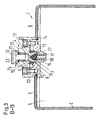
- einen Vertikalschnitt durch die Druckausgleichseinrichtung entsprechend der Schnittlinie B - B in
Fig. 2 , - Fig. 4
- eine Seitenansicht der Druckausgleichseinrichtung gemäß
Fig. 2 , und - Fig. 5
- einen Vertikalschnitt durch die Druckausgleichseinrichtung entsprechend der Schnittlinie A - A in
Fig. 4 . - Der zeichnerisch dargestellte Vorratsbehälter 1 dient der Aufnahme von Fett oder dgl. Schmierstoff für eine (nicht dargestellte) Schmierstoffpumpe. Der Vorratsbehälter 1 hat eine zylindrische Seitenwandung 2 und eine den Behälterinnenraum 5 nach oben abschließende Deckelwandung 3. In der Deckelwandung 3 ist eine Druckausgleichseinrichtung 4 angeordnet.
- Die Druckausgleichseinrichtung 4 weist in einem Durchtrittskanal 17, welcher sich in einem Oberteil 12 der Druckausgleichseinrichtung 4 koaxial zu dieser erstreckt, eine in einer von oben eingeschraubten Schraube 23 integrierte Membran auf, welche luftdurchlässig, aber wasserundurchlässig ist. Die Schraube 19 ist an ihrem Umfang mittels eines Dichtringes 21 abgedichtet.
- In dem Durchtrittskanal 17 unterhalb der Membran befindet sich ein Überdruckventil 27, dessen Ventilkörper 7 sich bei Überdruck in dem Behälterinnenraum 5, welcher z.B. beim Befüllen des Vorratsbehälters 1 mit neuem Schmierstoff auftritt, nach oben gegen einen Dichtsitz legt. Dadurch wird verhindert, dass Schmierstoff bis zur Membran gelangen und deren Funktion beeinträchtigen kann. Wird dagegen Schmierstoff aus dem Behälterinnenraum 5 von einer (nicht dargestellten) Schmierstoffpumpe abgesaugt, wird das Entstehen eines Unterdrucks im Behälterinnenraum 5 dadurch vermieden, dass über einen unter dem Schraubenkopf 23 freibleibenden Zufuhrschlitz 24 und über die Membran Luft vom Behälteraußenraum 6 in den Behälterinnenraum 5 nachströmen kann. Dabei öffnet das Überdruckventil 27. Der Bewegungsweg des Ventilkörpers 7 ist durch eine von unten in den Durchtrittskanal 17 eingesteckte Buchse 18 aus Kunststoff begrenzt.
- Das Oberteil 12 weist einen Umfangsrand 20 auf, mit welchem es auf einem Unterteil 13 der Druckausgleichseinrichtung 4 zentriert ist. Oberteil 12 und Unterteil 13 haben einen etwas größeren Durchmesser als eine Öffnung 11 in der Deckelwandung 3. Auf diese Weise können Oberteil 12 und Unterteil 13 unter Zwischenlage eines Dichtringes 14 am Rand der Öffnung 11 mittels Spannschrauben 25 festgespannt werden.
- Das Oberteil 12 ragt mit einem Mittelzapfen 15 durch das Unterteil 13 unter Freihaltung eines Austrittsspalts 16 für Luft und Schmierstoff beim Überfüllen hindurch. Oberhalb des Austrittsspalts 16 ist an dem Mittelzapfen 5 ein Dichtsitz 10 für einen Radialwellendichtring 9 ausgebildet, so dass ein Auslassventil 8 entsteht. Wie aus
Fig. 3 ersichtlich, hat der Radialwellendichtring 9 eine Dichtlippe oberhalb des Austrittsspalts 16, welche bei Druckbeaufschlagung von innen von dem Dichtsitz 10 abheben kann, so dass überschüssige Luft und Schmierstoff über radiale Auslasskanäle 26 austreten können. - Auf diese Weise ist ein Vorratsbehälter für eine Schmierstoffpumpe geschaffen, bei welchem ein Luftdruckausgleich sowohl beim Befüllen als auch beim Entleeren des Behälterinnenraums mit Schmierstoff erfolgt. Gleichwohl ist ein Einsatz unter Wasser möglich. Beim Überfüllen ist ferner ein Austreten von Schmierstoff über die Druckausgleichseinrichtung gewährleistet, ohne dass die luftdurchlässige, aber wasserundurchlässige Membran mit Schmierstoff in Berührung kommt und in ihrer Funktion beeinträchtigt wird. Die Druckausgleichseinrichtung bildet dabei eine leicht montierbare Baueinheit.
-
- 1
- Vorratsbehälter
- 2
- Seitenwandung
- 3
- Deckelwandung
- 4
- Druckausgleichseinrichtung
- 5
- Behälterinnenraum
- 6
- Behälteraußenraum
- 7
- Ventilkörper
- 8
- Auslassventil für Luft und Schmierstoff
- 9
- Radialwellendichtring
- 10
- Dichtsitz
- 11
- Öffnung
- 12
- Oberteil
- 13
- Unterteil
- 14
- Dichtring
- 15
- Mittelzapfen
- 16
- Austrittsspalt für Luft und Schmierstoff
- 17
- Durchtrittskanal für Luft
- 18
- Buchse
- 19
- Schraube mit integrierter Membran
- 20
- Umfangsrand
- 21
- Dichtring
- 22
- Gewinde
- 23
- Schraubenkopf
- 24
- Zufuhrschlitz für Luft
- 25
- Spannschrauben
- 26
- Auslasskanäle für Luft und Schmierstoff
- 27
- Überdruckventil
Claims (9)
- Vorratsbehälter zur Aufnahme von Fett oder dgl. Schmierstoff für eine Schmierstoffpumpe, mit einer z.B. zylindrischen Seitenwandung (2) und einer den Behälterinnenraum (5) nach oben abschließenden Deckelwandung (3), in welcher eine Druckausgleichseinrichtung (4) so angeordnet ist, dass der Behälterinnenraum (5) mit dem Behälteraußenraum (6) über eine luftdurchlässige, aber wasserundurchlässige Membran in Strömungsverbindung steht, dadurch gekennzeichnet, dass die Druckausgleichseinrichtung (4) ein Oberteil (12) und ein Unterteil (13) aufweist, wobei das Oberteil (12) das Unterteil (13) mit einem Mittelzapfen (15), an welchem ein Dichtsitz (10) für einen Radialwellendichtring (9) ausgebildet ist, unter Freihaltung eines geringen ringförmigen Austrittsspalts (16) für bei Überfüllen austretende Luft und Schmierstoff koaxial durchragt.
- Vorratsbehälter nach Anspruch 1, dadurch gekennzeichnet, dass die Membran in eine Schraube (19) integriert ist, welche im Bereich eines Durchtrittskanals (17) der Druckausgleichseinrichtung (4) einschraubbar ist.
- Vorratsbehälter nach Anspruch 1 oder 2, dadurch gekennzeichnet, dass die Membran ein textiles Material aufweist, auf welches Polytetrafluorethylen (Teflon) aufgebracht ist (Goretex).
- Vorratsbehälter nach einem der Ansprüche 1 bis 4, dadurch gekennzeichnet, dass die Druckausgleichseinrichtung (4) ein sich bei Überfüllen mit Schmierstoff öffnendes Auslassventil (8) aufweist.
- Vorratsbehälter nach Anspruch 4, dadurch gekennzeichnet, dass das Auslassventil (8) einen Radialwellendichtring (9) aufweist, welcher bei Druck von außen dichtet und dessen weiche Dichtlippe bei Druck von innen von einem Dichtsitz (10) abhebt.
- Vorratsbehälter nach einem der vorhergehenden Ansprüche, dadurch gekennzeichnet, dass die Druckausgleichseinrichtung (4) in einer Öffnung (11) der Deckelwandung (3) festspannbar ist.
- Vorratsbehälter nach einem der vorhergehenden Ansprüche, dadurch gekennzeichnet, dass die Druckausgleichseinrichtung (4) ein Oberteil (12) und ein Unterteil (13) aufweist, welche in einer Öffnung (11) der Deckelwandung (3) unter Zwischenlage eines Dichtringes (14) festspannbar sind.
- Vorratsbehälter nach einem der vorhergehenden Ansprüche, dadurch gekennzeichnet, dass in dem Durchtrittskanal (17) der Druckausgleichseinrichtung (4), in welchem die Membran angeordnet ist, vom Behälterinnenraum (5) aus gesehen vor der Membran ein unter im Behälterinnenraum (5) herrschenden Überdruck schließendes Rückschlagventil (27) angeordnet ist.
- Vorratsbehälter nach einem der vorhergehenden Ansprüche, dadurch gekennzeichnet, dass das Oberteil (12) mit einem Umfangsrand (20) auf den Unterteil (13) zentrierbar ist.
Applications Claiming Priority (3)
| Application Number | Priority Date | Filing Date | Title |
|---|---|---|---|
| DE20208365U DE20208365U1 (de) | 2002-05-29 | 2002-05-29 | Vorratsbehälter für Schmierstoffpumpe |
| DE20208365U | 2002-05-29 | ||
| PCT/EP2003/005386 WO2003100314A1 (de) | 2002-05-29 | 2003-05-23 | Vorratsbehälter für schmierstoffpumpe |
Publications (2)
| Publication Number | Publication Date |
|---|---|
| EP1507999A1 EP1507999A1 (de) | 2005-02-23 |
| EP1507999B1 true EP1507999B1 (de) | 2008-10-01 |
Family
ID=7971627
Family Applications (1)
| Application Number | Title | Priority Date | Filing Date |
|---|---|---|---|
| EP03735440A Expired - Lifetime EP1507999B1 (de) | 2002-05-29 | 2003-05-23 | Vorratsbehälter für schmierstoffpumpe |
Country Status (6)
| Country | Link |
|---|---|
| US (1) | US7159606B2 (de) |
| EP (1) | EP1507999B1 (de) |
| KR (1) | KR100641019B1 (de) |
| DE (2) | DE20208365U1 (de) |
| WO (1) | WO2003100314A1 (de) |
| ZA (1) | ZA200400735B (de) |
Families Citing this family (8)
| Publication number | Priority date | Publication date | Assignee | Title |
|---|---|---|---|---|
| US9845862B2 (en) * | 2006-04-17 | 2017-12-19 | W. L. Gore & Associates, Inc. | Axle vent |
| DE102006056257B4 (de) * | 2006-11-27 | 2013-05-29 | Günther Zimmer | Einwechselaggregat mit Kleinmengenschmiermittelspender |
| US8387755B2 (en) * | 2007-08-30 | 2013-03-05 | Caterpillar Inc. | Lubrication system and method of control |
| US8448750B2 (en) * | 2007-09-26 | 2013-05-28 | Caterpillar Inc. | Lubrication system level control |
| US9086186B2 (en) * | 2011-10-14 | 2015-07-21 | Lincoln Industrial Corporation | System having removable lubricant reservoir and lubricant refilling station |
| GB2518179B8 (en) * | 2013-09-12 | 2017-01-18 | Jaguar Land Rover Ltd | Filter device |
| US10639579B2 (en) | 2014-10-01 | 2020-05-05 | Donaldson Company, Inc. | Pleated tank vent |
| CN107206300B (zh) | 2015-01-28 | 2020-11-24 | 唐纳森公司 | 屏障式通气口组件 |
Family Cites Families (14)
| Publication number | Priority date | Publication date | Assignee | Title |
|---|---|---|---|---|
| US2273737A (en) * | 1939-12-30 | 1942-02-17 | Mahlon C Snyder | Vent device for gasoline containers and the like |
| US3326230A (en) * | 1965-10-18 | 1967-06-20 | Rca Corp | Valve discriminating means |
| US3425193A (en) * | 1967-03-15 | 1969-02-04 | Arthur F Emmerson | Sealed journal box with breather |
| DE2406719A1 (de) | 1974-02-13 | 1975-08-21 | Fritz Schaller | Niveaukontrolleinrichtung fuer behaelter mit zaehfluessigen und strukturviskosen fuellungen, insbesondere fuer schmierfette |
| US4512492A (en) * | 1983-12-12 | 1985-04-23 | Graybeal Walter C | Manhole closure with a single liquid impervious, two-way gas pressure relief valve |
| US4757654A (en) * | 1987-02-13 | 1988-07-19 | The United States Of America As Represented By The Secretary Of The Army | Blister pressure relief valve |
| WO1990001130A1 (de) * | 1988-07-21 | 1990-02-08 | Zahnradfabrik Friedrichshafen Ag | Druckausgleicher zwischen maschinengehäuse und umgebung |
| US4957522A (en) * | 1989-06-06 | 1990-09-18 | Brassell Gilbert W | Combination of a filter and a material permeable to gases but impermeable to liquids |
| US5348570A (en) * | 1993-04-05 | 1994-09-20 | Rockwell International Corporation | Axle housing breather |
| DE4433170C2 (de) | 1994-09-16 | 1998-07-02 | Lincoln Gmbh | Einrichtung zur Leerstandüberwachung eines Vorratsbehälters |
| US5752746A (en) * | 1995-12-15 | 1998-05-19 | Stemco Inc | Hubcap with vented closure |
| JP3219700B2 (ja) | 1996-09-18 | 2001-10-15 | 日東電工株式会社 | ベントフィルタ部材 |
| DE19809620C1 (de) * | 1998-03-06 | 1999-09-30 | Lincoln Gmbh | Vorrichtung zur Inhaltskontrolle eines Behälters |
| US20020195141A1 (en) * | 2001-06-26 | 2002-12-26 | Ruschke Rick R. | Check valve and filter assembly incorporating such valve, especially for water cooler assemblies |
-
2002
- 2002-05-29 DE DE20208365U patent/DE20208365U1/de not_active Expired - Lifetime
-
2003
- 2003-05-23 US US10/478,254 patent/US7159606B2/en not_active Expired - Lifetime
- 2003-05-23 EP EP03735440A patent/EP1507999B1/de not_active Expired - Lifetime
- 2003-05-23 WO PCT/EP2003/005386 patent/WO2003100314A1/de not_active Ceased
- 2003-05-23 DE DE50310578T patent/DE50310578D1/de not_active Expired - Lifetime
- 2003-05-23 KR KR1020047001303A patent/KR100641019B1/ko not_active Expired - Fee Related
-
2004
- 2004-01-29 ZA ZA200400735A patent/ZA200400735B/xx unknown
Also Published As
| Publication number | Publication date |
|---|---|
| KR20050002794A (ko) | 2005-01-10 |
| DE20208365U1 (de) | 2002-11-28 |
| US7159606B2 (en) | 2007-01-09 |
| ZA200400735B (en) | 2004-08-24 |
| WO2003100314A1 (de) | 2003-12-04 |
| KR100641019B1 (ko) | 2006-10-31 |
| DE50310578D1 (de) | 2008-11-13 |
| US20040144424A1 (en) | 2004-07-29 |
| EP1507999A1 (de) | 2005-02-23 |
Similar Documents
| Publication | Publication Date | Title |
|---|---|---|
| DE1907358C3 (de) | Pumpvorrichtung | |
| DE69636974T2 (de) | Ventileinheit zum einlass und auslass von flüssigkeiten | |
| EP0131928B1 (de) | Deckel mit Entlüftungsventil | |
| DE2414893A1 (de) | Ventil | |
| DE202015009718U1 (de) | Absperrkörper für ein Ventil und Ventil mit einem derartigen Absperrkörper | |
| DE1209103B (de) | Auswechselbarer OElfilter | |
| DE3734421A1 (de) | Ausgleichsbehaelter fuer eine hydraulische bremsanlage | |
| DE69724720T2 (de) | Behälter mit Vakuumentlastung | |
| EP1507999A1 (de) | Vorratsbeh lter f r schmierstoffpumpe | |
| DE112023002165T5 (de) | Druckausgleichsvorrichtung für ein Batteriegehäuse | |
| DE2252750B2 (de) | Kuehlerverschluss | |
| DE102021001258B4 (de) | Ventil zum Druckausgleich und/oder zur Notentlüftung eines Behälters, vorzugsweise eines Gehäuses einer Fahrzeugbatterie, sowie Behälter mit einem solchen Ventil | |
| WO2005065977A1 (de) | Entlüftungsventil | |
| DE60027304T2 (de) | Sicherheitsdichtung des schliesselements einer fülltüte für grossbehälter | |
| EP4094550B1 (de) | Gehäuse mit einer druckausgleichseinrichtung | |
| DE102022109454A1 (de) | Testleckvorrichtung | |
| CH644938A5 (en) | Device for preventing water hammer in a sanitary fitting | |
| DE2216483C2 (de) | Verschlußdeckel mit automatisch wirkendem Über- bzw. Unterdruck-Ausgleich | |
| DE2141619A1 (de) | Verschluß- und Belüftungsdeckel für Hydraulikflüssigkeits behälter | |
| DE102006015428B4 (de) | Be- und Entlüftungseinrichtung | |
| DE2757974B2 (de) | Einrichtung zum Zufuhren eines flüssigen Reinigungsmittels und zum Zuführen und Ableiten eines gasförmigen Strömungsmittels an einem Flüssigkeitstank, insbesondere Biertank | |
| DE1293092B (de) | Durch Schwerkraft betaetigtes Hilfsventil fuer zur Abgabe von dauernd unter Druck stehenden Fluessigkeiten bestimmte, mit einem Steigrohr versehene Behaelter | |
| DE3728542A1 (de) | Ausgleichsbehaelter | |
| DE7305218U (de) | Ventil | |
| DE102005029730A1 (de) | Ventil zur Be- und Entlüftung eines Behälters |
Legal Events
| Date | Code | Title | Description |
|---|---|---|---|
| PUAI | Public reference made under article 153(3) epc to a published international application that has entered the european phase |
Free format text: ORIGINAL CODE: 0009012 |
|
| 17P | Request for examination filed |
Effective date: 20030916 |
|
| AK | Designated contracting states |
Kind code of ref document: A1 Designated state(s): AT BE BG CH CY CZ DE DK EE ES FI FR GB GR HU IE IT LI LU MC NL PT RO SE SI SK TR |
|
| RBV | Designated contracting states (corrected) |
Designated state(s): DE FR GB IT |
|
| RAP1 | Party data changed (applicant data changed or rights of an application transferred) |
Owner name: LINCOLN GMBH |
|
| 17Q | First examination report despatched |
Effective date: 20071116 |
|
| GRAP | Despatch of communication of intention to grant a patent |
Free format text: ORIGINAL CODE: EPIDOSNIGR1 |
|
| GRAS | Grant fee paid |
Free format text: ORIGINAL CODE: EPIDOSNIGR3 |
|
| GRAA | (expected) grant |
Free format text: ORIGINAL CODE: 0009210 |
|
| AK | Designated contracting states |
Kind code of ref document: B1 Designated state(s): DE FR GB IT |
|
| REG | Reference to a national code |
Ref country code: GB Ref legal event code: FG4D Free format text: NOT ENGLISH |
|
| REF | Corresponds to: |
Ref document number: 50310578 Country of ref document: DE Date of ref document: 20081113 Kind code of ref document: P |
|
| REG | Reference to a national code |
Ref country code: DE Ref legal event code: R096 Ref document number: 50310578 Country of ref document: DE Effective date: 20081113 |
|
| PLBE | No opposition filed within time limit |
Free format text: ORIGINAL CODE: 0009261 |
|
| STAA | Information on the status of an ep patent application or granted ep patent |
Free format text: STATUS: NO OPPOSITION FILED WITHIN TIME LIMIT |
|
| 26N | No opposition filed |
Effective date: 20090702 |
|
| REG | Reference to a national code |
Ref country code: DE Ref legal event code: R097 Ref document number: 50310578 Country of ref document: DE Effective date: 20090702 |
|
| REG | Reference to a national code |
Ref country code: DE Ref legal event code: R082 Ref document number: 50310578 Country of ref document: DE Representative=s name: KEIL & SCHAAFHAUSEN PATENT- UND RECHTSANWAELTE, DE |
|
| REG | Reference to a national code |
Ref country code: DE Ref legal event code: R082 Ref document number: 50310578 Country of ref document: DE Representative=s name: KEIL & SCHAAFHAUSEN PATENT- UND RECHTSANWAELTE, DE Effective date: 20141202 Ref country code: DE Ref legal event code: R081 Ref document number: 50310578 Country of ref document: DE Owner name: SKF LUBRICATION SYSTEMS GERMANY GMBH, DE Free format text: FORMER OWNER: LINCOLN GMBH, 69190 WALLDORF, DE Effective date: 20141202 Ref country code: DE Ref legal event code: R081 Ref document number: 50310578 Country of ref document: DE Owner name: SKF LUBRICATION SYSTEMS GERMANY GMBH, DE Free format text: FORMER OWNER: LINCOLN GMBH & CO. KG, 69190 WALLDORF, DE Effective date: 20080904 |
|
| REG | Reference to a national code |
Ref country code: FR Ref legal event code: PLFP Year of fee payment: 13 |
|
| PGFP | Annual fee paid to national office [announced via postgrant information from national office to epo] |
Ref country code: GB Payment date: 20150521 Year of fee payment: 13 |
|
| PGFP | Annual fee paid to national office [announced via postgrant information from national office to epo] |
Ref country code: IT Payment date: 20150513 Year of fee payment: 13 Ref country code: FR Payment date: 20150521 Year of fee payment: 13 |
|
| GBPC | Gb: european patent ceased through non-payment of renewal fee |
Effective date: 20160523 |
|
| PG25 | Lapsed in a contracting state [announced via postgrant information from national office to epo] |
Ref country code: IT Free format text: LAPSE BECAUSE OF NON-PAYMENT OF DUE FEES Effective date: 20160523 |
|
| REG | Reference to a national code |
Ref country code: FR Ref legal event code: ST Effective date: 20170131 |
|
| PG25 | Lapsed in a contracting state [announced via postgrant information from national office to epo] |
Ref country code: FR Free format text: LAPSE BECAUSE OF NON-PAYMENT OF DUE FEES Effective date: 20160531 |
|
| PG25 | Lapsed in a contracting state [announced via postgrant information from national office to epo] |
Ref country code: GB Free format text: LAPSE BECAUSE OF NON-PAYMENT OF DUE FEES Effective date: 20160523 |
|
| PGFP | Annual fee paid to national office [announced via postgrant information from national office to epo] |
Ref country code: DE Payment date: 20220527 Year of fee payment: 20 |
|
| REG | Reference to a national code |
Ref country code: DE Ref legal event code: R071 Ref document number: 50310578 Country of ref document: DE |
|
| P01 | Opt-out of the competence of the unified patent court (upc) registered |
Effective date: 20230513 |