EP1507095B1 - Dispositif pour le soutien contrôlé de pièces sur des amortisseurs de vibration - Google Patents
Dispositif pour le soutien contrôlé de pièces sur des amortisseurs de vibration Download PDFInfo
- Publication number
- EP1507095B1 EP1507095B1 EP04006154A EP04006154A EP1507095B1 EP 1507095 B1 EP1507095 B1 EP 1507095B1 EP 04006154 A EP04006154 A EP 04006154A EP 04006154 A EP04006154 A EP 04006154A EP 1507095 B1 EP1507095 B1 EP 1507095B1
- Authority
- EP
- European Patent Office
- Prior art keywords
- screw
- hole
- head
- holder
- clamping plate
- Prior art date
- Legal status (The legal status is an assumption and is not a legal conclusion. Google has not performed a legal analysis and makes no representation as to the accuracy of the status listed.)
- Expired - Lifetime
Links
- 238000013016 damping Methods 0.000 claims abstract description 29
- 230000000007 visual effect Effects 0.000 claims abstract description 9
- 230000006835 compression Effects 0.000 claims description 5
- 238000007906 compression Methods 0.000 claims description 5
- 230000035939 shock Effects 0.000 abstract description 7
- 239000006096 absorbing agent Substances 0.000 abstract description 3
- 238000009434 installation Methods 0.000 description 4
- 229920001971 elastomer Polymers 0.000 description 3
- 239000000806 elastomer Substances 0.000 description 3
- 230000008719 thickening Effects 0.000 description 3
- 150000001875 compounds Chemical class 0.000 description 2
- 238000004519 manufacturing process Methods 0.000 description 2
- 239000000463 material Substances 0.000 description 2
- 230000007935 neutral effect Effects 0.000 description 2
- 230000005540 biological transmission Effects 0.000 description 1
- 238000011161 development Methods 0.000 description 1
- 230000018109 developmental process Effects 0.000 description 1
- 238000010586 diagram Methods 0.000 description 1
- 238000005259 measurement Methods 0.000 description 1
- 230000002093 peripheral effect Effects 0.000 description 1
- 230000002441 reversible effect Effects 0.000 description 1
- 239000013589 supplement Substances 0.000 description 1
- 230000002123 temporal effect Effects 0.000 description 1
- 230000036962 time dependent Effects 0.000 description 1
Images

Classifications
-
- F—MECHANICAL ENGINEERING; LIGHTING; HEATING; WEAPONS; BLASTING
- F16—ENGINEERING ELEMENTS AND UNITS; GENERAL MEASURES FOR PRODUCING AND MAINTAINING EFFECTIVE FUNCTIONING OF MACHINES OR INSTALLATIONS; THERMAL INSULATION IN GENERAL
- F16F—SPRINGS; SHOCK-ABSORBERS; MEANS FOR DAMPING VIBRATION
- F16F1/00—Springs
- F16F1/36—Springs made of rubber or other material having high internal friction, e.g. thermoplastic elastomers
- F16F1/38—Springs made of rubber or other material having high internal friction, e.g. thermoplastic elastomers with a sleeve of elastic material between a rigid outer sleeve and a rigid inner sleeve or pin, i.e. bushing-type
- F16F1/3842—Method of assembly, production or treatment; Mounting thereof
-
- F—MECHANICAL ENGINEERING; LIGHTING; HEATING; WEAPONS; BLASTING
- F16—ENGINEERING ELEMENTS AND UNITS; GENERAL MEASURES FOR PRODUCING AND MAINTAINING EFFECTIVE FUNCTIONING OF MACHINES OR INSTALLATIONS; THERMAL INSULATION IN GENERAL
- F16F—SPRINGS; SHOCK-ABSORBERS; MEANS FOR DAMPING VIBRATION
- F16F2230/00—Purpose; Design features
- F16F2230/0047—Measuring, indicating
-
- F—MECHANICAL ENGINEERING; LIGHTING; HEATING; WEAPONS; BLASTING
- F16—ENGINEERING ELEMENTS AND UNITS; GENERAL MEASURES FOR PRODUCING AND MAINTAINING EFFECTIVE FUNCTIONING OF MACHINES OR INSTALLATIONS; THERMAL INSULATION IN GENERAL
- F16F—SPRINGS; SHOCK-ABSORBERS; MEANS FOR DAMPING VIBRATION
- F16F2230/00—Purpose; Design features
- F16F2230/0082—Dimensional tolerances, e.g. play between mechanical elements
Definitions
- the invention relates to a device for the controlled storage of components on vibration dampers, compensated with the dimensional variations of a stored component in three levels by an adjustment mechanism of the device and the sinking depth is visually displayed in the vibration.
- an elastic bearing element is known with which the support of a component is realized with respect to a foundation.
- This bearing element consists of a bearing base, a bearing cap and an elastomeric block lying between the two parts.
- the component to be supported for example a motor or transmission foot (provided according to the publication), is braced against the bearing cap.
- a central fixing screw is screwed into an intermediate part, which is supported against the bearing cap.
- a nut is provided between the component and the bearing cap a height adjustment part is arranged, which is divided into a lower part and an upper part. The upper part can be adjusted in height by means of a thread by turning relative to the lower part.
- height adjustment part is formed from the fixedly connected to the bearing cap lower part and a height-adjustable by means of the thread relative to the lower part upper part. This measure is therefore necessary to ensure, for example, an alignment of a (not shown in the figure of the publication) motor shaft with gear parts.
- the central fastening screw has a central bore, through which a threaded bolt can be inserted.
- the threaded bolt has at its upper end a cap, so that for variable fixing a locking of the cap over the threaded bolt by means of a self-locking hex nut is executable.
- the threaded bolt in the central bore can be locked in a predetermined position by a ball lock.
- the height adjustment part is formed from so-called washers, which are inserted between the bearing cap and the component.
- This bearing element in which the need to compensate for setting operations of an elastomeric block, which is used, for example, for cushioning and vibration damping, is easily detected without the use of suitable measuring devices will hardly be due to the functions of its components, existing deviations of a stored Compensate component in all three levels within a predefined setting range.
- the compensation is implemented only by means of a height adjustment (height adjustment) on the bearing element, the requirement of which will be due to a time-dependent lowering of the elastomer block, the material will correlate with a temporal influence underlying change in shape of the elastomer block, which is why a lowering of that elastomer block hardly influenced can be.
- the invention has for its object to provide a device for the controlled storage of components on vibration dampers, be compensated with the existing dimensional deviations of a so-mounted component in all three levels within a predefined setting range. Furthermore, a rational replacement of the vibration damper should be made possible with this device, without the stored component is changed in position. Likewise, a visual adjustment mechanism is provided to controllably ensure the optimum adjustment of the mounted component by means of the device on the characteristic of the vibration damper, without requiring visual contact with the (possibly located outside an accessible installation position) vibration damper.
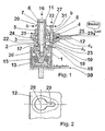
- Fig. 1 the structure of the device for the controlled storage of components is shown on a vibration damper, whose operation will be explained with reference to this illustration.
- the device comprises two clamping plates 3 and 4, between which a so-called holder 12, which is also referred to as a “bearing block”, attached (respectively clamped) is.
- This holder 12 is fixed to a (generally shown in FIG.) Component so that the load (s) and the mechanical vibrations on the holder 12 and other additional means (connecting and fixing elements of the device) is evenly distributed to a vibration damper (be ).
- the latter will absorb and balance the load (s) and body vibration (s) transmitted to it (of the holder-mounted component) via a damping body 15.
- the structure of the device is mainly by a lower clamping plate 3 (threaded plate), an upper clamping plate 4 (perforated plate), a nut 5 (lock nut), a fastening head screw 6, a (meaning screw-underlay) washer 7, a hollow body adjusting screw 2, a hollow body axial guide screw 8, an adjusting pin 9, a compression spring 10 and various fuse wire, which is guided by designated securing holes 11 in the respective screw head completes.
- the plate-like designed and component-connected holder 12 (bracket) is structurally designed and attached to the component so that the loads are evenly distributed, wherein in the disassembled state of the holder 12 access to the vibration damper 1 for its removal and installation in a confined space of the component - Depending on the design - also from the interior of the component to which the holder 12 are attached, is ensured.
- the vibration damper 1 is attached (expediently before the mounting of the holder 12) to its substructure (according to FIG. 1) or to a supporting body 14 (according to FIG. 5) fastened to the structure 30.
- the hollow body axial adjusting head screw 2 is screwed through the upper clamping plate 4 and the holder 12 in the lower clamping plate 3 (threaded plate) up to an example middle setting position and moved over the mounting terminal of the vibration damper 1, wherein the mobility of these clamping plates 3 and 4, the horizontal deviations be compensated.
- the mounting head screw 6, which is guided in the hollow body axial adjustment head screw 2, is initially screwed loosely into the vibration damper 1, whereby the mounting head screw 6 is positioned in its horizontal plane.
- the position of the holder 12 fixed to the component in the horizontal plane is determined.
- the hollow body adjusting head screw 2 is rotated in the lower clamping plate 3 (threaded plate) and thus adjusted the height of the component, which are balanced at the same time all vertical deviations of the vibration damper 1 with its base and the dimensional deviations of the component. This determines the position of the component in the vertical plane.
- a nut 5 on the hollow-body-axial adjusting head screw 2 is passed over the upper clamping plate 4 (perforated plate) with the lower clamping plate 3 (threaded plate) at a predetermined position Tightening torque.
- the mounting head screw 6 which is guided in the hollow body adjusting head screw 2, fixed to the vibration damper 1 with a predetermined torque.
- the clamped connections can not be solved, the mounting head screw 11, possibly also the hollow body adjusting head screw 2, the nut 5 (lock nut) and possibly also the hollow body axial guide screw 8 secured with a locking wire against rotation or loosening the screw (s) ,
- the storage on corresponding vibration dampers 1 can be construed constructively different depending on the requirements and taking into account the resulting in sum deviations. For the adjustment, attachment and securing of this storage on vibration dampers 1 you will be able to use commercially available tool in the rule.
- a device for controlled storage of a component on a vibration damper 1 which compensates dimensional deviations in three levels and produces a positive and non-positive connection.
- axial adjusting head screw 2 With the upper clamping plate 4 (perforated plate), with the lower clamping plate 3 (threaded plate) out, which is fixedly connected to the holder 12 (bearing block) of the component and itself move within a defined path in both horizontal axes and thus can be adjusted.
- the holder 12 By rotation of the hollow body axial adjusting head screw 2 in the lower clamping plate 3 (threaded plate) with-defined bolt length in the vertical axis (nraum) the holder 12 (bracket) and thus the component attached to it in the vertical plane is moved (lowered or raised) respectively set.
- the nut 5 (lock nut) is tightened after completion of the horizontal and vertical settings with a defined torque, thereby the form-fitting manner, the horizontal position of the holder 12 (holder-mounted component) and the vertical position of the holder 12 (the holder-mounted component) is fixed.
- the fastening head screw 6 is connected to the final attachment of the thus set holder 12 (the thus position-fixed component) with a predetermined torque on the hollow body axial adjusting head screw 2 with the vibration damper 1 positively.
- the adjusting pin 9 is guided by the hollow body axial guide screw 8 and in conjunction with the hollow body axial adjusting head screw 2, the setting on the (explained later) elements: "Kimme” and "grain” performed.
- To replace the bearing parts and / or the vibration damper 1 after loosening the mounting head screw 6 from the vibration damper 1 and the clamping plate countered nut 5 is relieved by unscrewing the Einstellkopfschraube 2 from the lower clamping plate 3 (threaded plate) of the holder 12 (the holder-mounted component). This allows the parts of the device to be removed and installed again in the reverse order.
- By fixing the hollow body axial guide screw head 8 a rotation during actuation of the hollow body axial adjusting head screw 2 is excluded.
- the lower and upper clamping plate 3 and 4 are parallel to the surface of a support surface 17 of the damping body 15, the position of which largely coincides with the base of the housing 13, arranged between the bearing surfaces 19 and 20 of the holder 12 is clamped.
- the clamping plates 3 and 4 and the holder 12 are each two holes which are arranged spaced along a longitudinal plate axis 21, except.
- a hollow axial adjustment head screw 2 is positioned, which is guided through a first hole 24 of the upper clamping plate 4.
- the screw thread of the adjusting head screw 2 is screwed to the first threaded hole 22 to a middle screw setting position of the lower clamping plate 3.
- a third threaded hole 26 is recessed in the support surface 17 of the damping body 15, in which a mounting head screw 6, guided by the cavity of the adjusting screw 2 is screwed.
- the latter is screwed so that the screw bolt end-side screw hollow cross-section of the adjusting head screw 2 is circumferentially fastened to the third threaded hole 26 on the support surface 17 of the damping body 15.
- a hollow body axial guide screw 8 is guided through a second hole 25 of the upper clamping plate 4, the screw thread is screwed to the second threaded hole 23 of the lower clamping plate 3.
- the screw head of the guide screw 8 is tightened against the upper clamping plate 4 with a defined screw torque.
- an adjusting pin 9 is guided axially movable, which is positioned at right angles to a support surface 18.
- the latter is arranged on the housing side and is a partial region of the top surface of the housing 13.
- the cross section of the pin bolt is then thickened (due to the clamping of the compression spring 10) bolt end side, so that the spring ends can press against this thickening and against the screw end of the guide screw 8.
- the bolt diameter d B of the thickening is smaller than the hole diameter d S of the upper clamping plate 4 in the region of the screw head of the guide screw 8 so that it is freely movable in the clamping plate 4 and thus also an additional clamping, in addition to the lock nut 5, allows.
- a measuring head with a rotationally symmetrical wedge-shaped recess (rear sight) is arranged.
- the damping body 15 the function of which comprises a plurality of elements which are not discussed further (for reasons) comprises - in addition to these further housing-internally arranged and functionally linked elements - the aforementioned damping body 15, which (functionally considered) an axially spring-back and spring-back element is. With these functionally linked elements, the damping is implemented by the vibration damper 1.
- the support surface 17 of the damping body 15 is located in parallel, as are the lower and upper clamping plate 3 and 4 and the latter clamped between the holders 12, which are also arranged in parallel, wherein the holder 12 is fixed to a right-angle member.
- the screw thread of the adjusting head screw 2 is screwed to the inner thread of the first threaded hole 22 of the lower clamping plate 3 to a middle screw setting position. If the screw head 21 of the adjusting head screw 2 is shaped to a measuring edge S tapered to the screw head circumference, and a measuring head with notch 27, which has a notch at the upper end of the pin bolt of the adjusting pin 9, whose recess is also parallel, the measuring edge S as a grain and the notch used as a rear sight, with which a visual adjustment mechanism is realized, with which the bearing of the component, which is mechanically connected to the holder 12, significantly on the alignment 31 between the sight and grain during different setting situations (according to Figures 3 to 6) is visually inspected.
- a second screw axis 18 of the guide screw 8 is screw axis parallel and definitely spaced from the first screw axis 16 of the adjusting head screw 2 is arranged.
- the cavity diameter d B in the region of the screw bolt of the guide screw 8 is larger than the bolt diameter d S (slot) of the guide screw 8 in the region of the screw head.
- the bolzenend workede diameter of the thickening of the adjusting pin 9 is to be smaller than the cavity diameter screw d S (threaded inside diameter of the lower clamping plate 3) in the region of the screw head of the guide screw 8 at any time, the guiding head screw 8 including the adjusting pin.
- Fig. 2 the mounting opening for the device for the controlled storage of components on a vibration damper in the holder 12 is shown, which is designed as a flat plate, in the profile cross section, a third hole 28 (circular hole) and an adjacent fourth hole 29 (slot ), whose concurrent to the circular hole extending perforation is directed to the center of the circular hole, is recessed, the hole recesses open into one another.
- the hole diameter of the circular hole is larger than the outer diameter of the adjusting head screw 2
- the hole diameter of the long hole is larger than the outer diameter of the guide screw 8.
- the outer diameter of the third hole 28 is significantly larger than the screw diameter of the adjusting head screw 2, so that the required setting is achieved, and formed as a slot fourth hole 29 in width slightly larger than the screw diameter of the guide screw 8 and also in length is large enough not to hinder the full freedom of movement of the adjusting head screw 2, and thus at the same time in the holder to be fastened 12 (before adjustment of the device) is movable and secured against rotation
- FIG. 3 shows the unloaded position of a device in a component connecting to the vibration damper 1, wherein a visible height difference SL is displayed between the sight and the grain.
- the setting of the device without height deviation is revealed via the adjusting pin 9.
- the setting of a structurally (for example +3 mm tolerance compensation) vertically raised device is shown in which after adjustment with the adjusting head 2, the tolerances of +3 mm were compensated.
- the setting of a structurally (for example, -3 mm tolerance compensation) vertically lowered device is shown in which after adjustment with the adjusting head screw 2, the slip deviation of -3 mm has been compensated. From these figures 3 to 6 it is easy to recognize the configuration (s) once in the unloaded state and three times in the loaded state.
Claims (24)
- Dispositif pour le soutien contrôlé de pièces, avec un amortisseur de vibrations (1) dont le boîtier (13) peut être fixé à une structure (30), à l'intérieur du boîtier étant disposé un corps amortisseur (15) qui absorbe les sollicitations mécaniques et les vibrations qui lui sont transmises par une pièce à laquelle peut être fixé un organe porteur (12) ou qui sont imposées à cette pièce, l'organe porteur (12) transmettant les sollicitations de la pièce à l'amortisseur de vibrations (1) par l'intermédiaire d'éléments supplémentaires de liaison et de fixation, caractérisé en ce que, parallèlement à une portée (17) du corps amortisseur (15), sont disposées des plaques de serrage inférieure et supérieure (3, 4) entre lesquelles est serré l'organe porteur (12), une vis de réglage à tête à corps axial creux (2) positionnée perpendiculairement sur la surface d'appui (17) traverse des trous superposés de cet ensemble plaques de serrage-organe porteur, parmi lesquels un trou associé à la plaque de serrage inférieure (3) est conformé en premier trou taraudé (22) dans lequel la vis de réglage à tête (2) est vissée jusqu'à une position de réglage de vis définie, une vis de fixation à tête (6) traverse la cavité de vis, disposée axialement par rapport à un premier axe de vis (16), de la vis de réglage à tête (2) et est positionnée et vissée dans un troisième trou taraudé (26) du corps amortisseur (15) qui est ainsi positionné et vissé au moyen de celui-ci dans le prolongement du premier axe de vis (16), un écrou de vis (5) est vissé sous une tête de vis (20) de la vis de réglage à tête (2) et est serré contre la plaque de serrage supérieure (4), une vis de guidage à tête à corps axial creux (8) traverse parallèlement et à distance du premier axe de vis (16) des trous supplémentaires superposés de l'ensemble plaques de serrage-organe porteur, parmi lesquels un trou supplémentaire associé à la plaque de serrage inférieure (3) est conformé en second trou taraudé (23) dans lequel est vissée la vis de guidage à tête (8) dont la tête de vis est appliquée contre la plaque de serrage supérieure (4), et une broche d'ajustage (9) traverse la cavité de vis, disposée axialement par rapport à un second axe de vis (32), de la vis de guidage à tête (8) et est positionnée avec une liberté de mouvement axial et perpendiculairement sur une surface d'appui (18), laquelle se trouve sur le bord du boîtier et constitue une zone partielle de la surface de recouvrement du boîtier (13), à la broche d'ajustage (9) étant associée, à son extrémité opposée, une tête de mesure (27) qui peut être amenée dans l'alignement de l'arête inférieure opposée de mesure de la tête de vis de la vis de réglage à tête (2) et qui constitue un mécanisme d'ajustage visuel.
- Dispositif selon la revendication 1, caractérisé en ce que dans l'organe porteur (12) et dans les deux plaques de serrage (3, 4) sont réalisés l'un au-dessus de l'autre et à distance l'un de l'autre deux trous selon un axe longitudinal de profil (21), les trous des plaques de serrage (3, 4) étant coïncidents, et les trous de la plaque de serrage inférieure (3) étant conformés en trous taraudés (22, 23).
- Dispositif selon une des revendications 1 ou 2, caractérisé en ce que la vis de réglage à tête (2) traverse un premier trou (24) de la plaque de serrage supérieure (4) et un troisième trou (28) de l'organe porteur (12) et son filetage est vissé dans le premier trou taraudé (22) de la plaque de serrage inférieure (3).
- Dispositif selon la revendication 1, caractérisé en ce que la vis de fixation à tête (6) est positionnée sur la portée (17) du corps amortisseur (15), de façon que la section transversale creuse de vis de la vis de réglage (2) soit positionnée en périphérie du troisième trou taraudé (26) du corps amortisseur (15).
- Dispositif selon la revendication 1, caractérisé en ce que la liaison vissée de l'écrou de vis (5) appliqué avec un couple de vissage défini contre la plaque de serrage supérieure (4) crée une liaison par conjugaison de forces avec l'organe porteur (12) dans la position plane de la pièce fixée à celui-ci et une liaison par complémentarité de formes dans la position perpendiculaire à celle-ci.
- Dispositif selon la revendication 1, caractérisé en ce que la vis de guidage à tête (8) traverse un second trou (25) de la plaque de serrage supérieure (4) et un quatrième trou (29), conformé en trou oblong, de l'organe porteur (12), et son filetage est vissé dans le second trou taraudé (23) de la plaque de serrage inférieure (3).
- Dispositif selon la revendication 1, caractérisé en ce que le diamètre extérieur de la tige filetée de la vis de réglage à tête (2) est supérieur à celui de la vis de guidage à tête (8).
- Dispositif selon une des revendications 1 ou 2, caractérisé en ce que l'organe porteur (12) est conformé en plaque plane, dans la section transversale profilée de laquelle sont ménagés le troisième trou (28) conformé en trou circulaire et, à côté de celui-ci, le quatrième trou (29) qui est conformé en trou oblong et dont la perforation de même sens que le troisième trou (28) est orientée vers le centre du trou circulaire, les évidements des trous débouchant l'un dans l'autre.
- Dispositif selon la revendication 8, caractérisé en ce que le diamètre de trou du troisième trou (28) est plus grand que le diamètre extérieur de la vis de réglage à tête (2) de la valeur nécessaire à la compensation des tolérances prévue dans ce plan, et le diamètre de trou et la longueur du quatrième trou (29) autorisent, avec le diamètre extérieur de la vis de guidage à tête (8), des mouvements libres sur toute la zone de réglage tant que la plaque de serrage inférieure (3) n'est pas vissée à fond avec la plaque de serrage supérieure (4) par l'intermédiaire de l'écrou de vis (5) et de la vis de guidage à tête (8).
- Dispositif selon la revendication 1, caractérisé en ce que le corps amortisseur (15) est un moyen à enfoncement et retour élastiques à angle droit qui, avec d'autres moyens disposés à l'intérieur du boîtier et associés fonctionnellement à lui, permet à l'amortisseur de vibrations (1) de réaliser l'amortissement.
- Dispositif selon la revendication 1, caractérisé en ce que la portée (17) du corps amortisseur (15), les plaques de serrage inférieure et supérieure (3, 4) et l'organe porteur (12) serré entre ces dernières sont disposés parallèlement.
- Dispositif selon une des revendications 1 ou 11, caractérisé en ce que l'organe porteur (12) peut être fixé à une pièce exerçant une sollicitation principalement verticale.
- Dispositif selon la revendication 1, caractérisé en ce que le filetage de la vis de réglage à tête (2) est vissé dans le taraudage du premier trou taraudé (22) de la plaque de serrage inférieure (3) jusqu'à une position moyenne de réglage de vis.
- Dispositif selon la revendication 1, caractérisé en ce que la tête de vis (20) de la vis de réglage à tête (2) présente la forme d'une arête de mesure (S) qui va en se rétrécissant à partir de la périphérie de la tête de vis.
- Dispositif selon la revendication 1, caractérisé en ce qu'à l'extrémité de la broche d'ajustage (9) se trouve un pied d'appui (19) sur lequel est appliqué un ressort de compression (10) dont les extrémités de ressort portent sur le pied d'appui (19) et sur la tige filetée de la vis de guidage à tête (8).
- Dispositif selon une des revendications 1 ou 15, caractérisé en ce que, sur le côté de la broche d'ajustage (9) opposé au pied d'appui (19), une tête de mesure (27), dans la périphérie de laquelle est ménagée une encoche, est reliée à la broche d'ajustage (9).
- Dispositif selon une des revendications 1, 15 ou 16, caractérisé en ce qu'entre la tête de mesure (27) de la broche d'ajustage (9) et l'arête de mesure de la tête de vis (20) de la vis de réglage à tête (2) peut être opéré un alignement (31) dont la position est déterminante pour le contrôle visuel de la sollicitation mécanique exercée par la pièce sur le corps amortisseur (15) de l'amortisseur de vibrations (1).
- Dispositif selon une des revendications 1 ou 17, caractérisé en ce que l'alignement (31) est réalisé avec l'encoche servant de cran de mire et avec l'arête de mesure (S) servant de guidon de visée.
- Dispositif selon la revendication 1, caractérisé en ce que le diamètre (dB) de la vis de guidage à tête (8) est plus petit que le diamètre de cavité (dS) du quatrième trou (29), conformé en trou oblong, de l'organe porteur (12) et du second trou (25) de la plaque de serrage supérieure (4).
- Dispositif selon la revendication 1, caractérisé en ce que l'axe de vis (32) de la vis de guidage (8) est disposé parallèlement et nettement à distance de l'axe de vis (16) de la vis de réglage (2).
- Dispositif selon une des revendications 1, 15 ou 16, caractérisé en ce que le diamètre du pied d'appui (19) de la broche d'ajustage (9) est plus petit que le diamètre de cavité (dS) du quatrième trou (29) de l'organe porteur (12) ainsi que du second trou (25) de la plaque de serrage supérieure (24) et du diamètre intérieur libre taraudé du trou taraudé (23).
- Dispositif selon la revendication 15, caractérisé en ce qu'une tête de mesure est disposée à l'extrémité de la broche d'ajustage (9) au-dessus de la tête de vis de la vis de guidage à tête (8).
- Dispositif selon la revendication 1, caractérisé en ce que le boîtier (13) est fixé à la surface de base par l'intermédiaire d'un corps d'appui (14) qui peut être fixé à une surface de pose non amortie de la structure (30).
- Dispositif selon la revendication 1, caractérisé en ce que toutes les liaisons vissées susceptibles de se détacher accidentellement sont reliées chacune par un fil métallique de sécurité qui traverse un trou de sécurité (11) placé respectivement sur la tête de vis de la vis de fixation à tête (6) et dans la tête de vis de la vis de guidage à tête (8), ces éléments ainsi reliés par complémentarité de formes étant protégés contre un détachement accidentel.
Applications Claiming Priority (2)
| Application Number | Priority Date | Filing Date | Title |
|---|---|---|---|
| DE10337208 | 2003-08-13 | ||
| DE10337208A DE10337208B3 (de) | 2003-08-13 | 2003-08-13 | Vorrichtung zur kontrollierten Lagerung von Bauteilen auf Schwingungsdämpfern |
Publications (3)
| Publication Number | Publication Date |
|---|---|
| EP1507095A2 EP1507095A2 (fr) | 2005-02-16 |
| EP1507095A3 EP1507095A3 (fr) | 2005-09-28 |
| EP1507095B1 true EP1507095B1 (fr) | 2006-06-28 |
Family
ID=33305249
Family Applications (1)
| Application Number | Title | Priority Date | Filing Date |
|---|---|---|---|
| EP04006154A Expired - Lifetime EP1507095B1 (fr) | 2003-08-13 | 2004-03-16 | Dispositif pour le soutien contrôlé de pièces sur des amortisseurs de vibration |
Country Status (5)
| Country | Link |
|---|---|
| US (1) | US7011187B2 (fr) |
| EP (1) | EP1507095B1 (fr) |
| AT (1) | ATE331904T1 (fr) |
| DE (2) | DE10337208B3 (fr) |
| ES (1) | ES2266940T3 (fr) |
Cited By (1)
| Publication number | Priority date | Publication date | Assignee | Title |
|---|---|---|---|---|
| CN110645317A (zh) * | 2019-10-09 | 2020-01-03 | 广州大学 | 一种储罐用多维减隔震装置 |
Families Citing this family (9)
| Publication number | Priority date | Publication date | Assignee | Title |
|---|---|---|---|---|
| DE102004034578A1 (de) * | 2004-07-16 | 2006-02-16 | Zf Friedrichshafen Ag | Gummilager mit Wegbegrenzern |
| NL1028712C2 (nl) * | 2005-04-06 | 2006-10-09 | Mach Support B V | Trillingsdemper voorzien van een nastelsysteem alsmede een dergelijk nastelsysteem, samenstel voorzien van een dergelijke trillingsdemper of dergelijk nastelsysteem als ook het gebruik van een dergelijke trillingsdemper en dergelijk nastelsysteem. |
| FR2915176B1 (fr) * | 2007-04-20 | 2009-07-10 | Airbus France Sa | Mat d'accrochage de moteur pour aeronef disposant d'une attache moteur arriere pourvue d'un ecrou a barillet |
| US7474532B1 (en) | 2007-08-30 | 2009-01-06 | International Business Machines Corporation | Heat sink restraints for calibrated mating pressure and shock absorption |
| DE102008022467A1 (de) * | 2008-05-07 | 2009-11-12 | Astrium Gmbh | Feder-Dämpfungssystem |
| CN108757391B (zh) * | 2018-07-27 | 2024-02-06 | 黄石东贝压缩机有限公司 | 一种压缩机机芯减振支撑结构以及压缩机 |
| CN110092295A (zh) * | 2019-05-31 | 2019-08-06 | 北京晶品特装科技有限责任公司 | 连接组件 |
| US11696427B2 (en) * | 2019-11-15 | 2023-07-04 | International Business Machines Corporation | Configurable printed-circuit-board-assembly component pressing fixture |
| CN114909418B (zh) * | 2022-05-31 | 2023-09-22 | 宁波竤远船舶动力设备有限公司 | 一种船用柴油机轴向减震装置及柴油机 |
Family Cites Families (8)
| Publication number | Priority date | Publication date | Assignee | Title |
|---|---|---|---|---|
| US2367830A (en) * | 1942-10-27 | 1945-01-23 | Firestone Tire & Rubber Co | Resilient mounting |
| US2940784A (en) * | 1956-06-06 | 1960-06-14 | William B Fell | Precision threaded adjustment |
| DE2131917A1 (de) * | 1971-06-26 | 1973-01-11 | Siemens Ag | Hoehenverstellbare auflagerung eines maschinengehaeuseteiles an einem auflagekoerper |
| JPH0724674Y2 (ja) * | 1989-08-24 | 1995-06-05 | 東海ゴム工業株式会社 | サスペンション用アッパサポート |
| DE4141850C2 (de) * | 1991-12-18 | 1995-10-05 | Man Nutzfahrzeuge Ag | Elastisches Lagerelement |
| JP3663482B2 (ja) * | 1999-05-27 | 2005-06-22 | 東洋ゴム工業株式会社 | 切替型液封入式防振装置 |
| JP2002295440A (ja) * | 2001-04-04 | 2002-10-09 | Isuzu Motors Ltd | テーブル装置 |
| JP3783100B2 (ja) * | 2001-08-07 | 2006-06-07 | 東洋ゴム工業株式会社 | 液封入式防振装置 |
-
2003
- 2003-08-13 DE DE10337208A patent/DE10337208B3/de not_active Expired - Fee Related
-
2004
- 2004-03-16 EP EP04006154A patent/EP1507095B1/fr not_active Expired - Lifetime
- 2004-03-16 ES ES04006154T patent/ES2266940T3/es not_active Expired - Lifetime
- 2004-03-16 AT AT04006154T patent/ATE331904T1/de not_active IP Right Cessation
- 2004-03-16 DE DE502004000867T patent/DE502004000867D1/de not_active Expired - Lifetime
- 2004-04-05 US US10/818,980 patent/US7011187B2/en not_active Expired - Fee Related
Cited By (1)
| Publication number | Priority date | Publication date | Assignee | Title |
|---|---|---|---|---|
| CN110645317A (zh) * | 2019-10-09 | 2020-01-03 | 广州大学 | 一种储罐用多维减隔震装置 |
Also Published As
| Publication number | Publication date |
|---|---|
| DE502004000867D1 (de) | 2006-08-10 |
| ES2266940T3 (es) | 2007-03-01 |
| US7011187B2 (en) | 2006-03-14 |
| US20050035510A1 (en) | 2005-02-17 |
| EP1507095A3 (fr) | 2005-09-28 |
| EP1507095A2 (fr) | 2005-02-16 |
| DE10337208B3 (de) | 2004-11-18 |
| ATE331904T1 (de) | 2006-07-15 |
Similar Documents
| Publication | Publication Date | Title |
|---|---|---|
| EP2217469B1 (fr) | Élément de positionnement | |
| DE1800960C3 (de) | Vorrichtung zur Dämpfung von Schwingungen | |
| EP2614002B1 (fr) | Dispositif de fixation | |
| EP1507095B1 (fr) | Dispositif pour le soutien contrôlé de pièces sur des amortisseurs de vibration | |
| DE102005056661A1 (de) | Vibrations-Dämpfungsvorrichtung für Lenkungssysteme | |
| DE69918969T2 (de) | Motorlager | |
| EP0685622B1 (fr) | Procédé pour le montage d'un composant pivotant de véhicule et charnière pour la réalisation | |
| DE102004018736A1 (de) | Verbindungselement | |
| WO2020109305A1 (fr) | Connecteur central pour véhicules pourvu d'un accumulateur à haute tension | |
| DE2832773A1 (de) | Fahrzeugaufhaengung mit eingebauter daempfung | |
| EP3251571B1 (fr) | Charnière de pivotement pour une porte | |
| EP3973126B1 (fr) | Ferrure de meuble | |
| DE3730176A1 (de) | Verstelleinrichtung fuer das gelenk eines lenkers einer radaufhaengung | |
| DE2537833A1 (de) | Vorrichtung zur freiwegbegrenzung fuer ein elastisch-nachgiebiges gummi-metall- element, insbesondere zur lagerung von kraftfahrzeug-motoren | |
| DE102007036959B4 (de) | Bodenplatte für eine Sensorbaugruppe, Trägerkörper zur Befestigung der Bodenplatte, Sensorbaugruppe und Befestigungssystem | |
| DE3432768C2 (fr) | ||
| DE102015222873B4 (de) | Vorrichtung zur Höhenverstellung eines Fahrzeugaufbaus eines Kraftfahrzeuges | |
| EP0762012A1 (fr) | Amortisseur dynamique | |
| DE3402809A1 (de) | Scharnierbefestigung fuer fahrzeugtueren | |
| WO2019101423A1 (fr) | Système de fixation pour véhicule automobile pour fixer un premier composant de véhicule automobile à un deuxième composant de véhicule automobile | |
| EP0925420B1 (fr) | Ferrure de serrage pour assembler des vitres | |
| DE2922543A1 (de) | Stuetzklammer | |
| DE10053372C1 (de) | Türblatt mir Scharnier für den Aufbau eines Lastfahrzeuges sowie Lagerplatte für ein solches Scharnier | |
| EP4043680B1 (fr) | Logement de paumelle | |
| EP1588980A2 (fr) | Appareil de manipulation avec équipement auxilliaire |
Legal Events
| Date | Code | Title | Description |
|---|---|---|---|
| PUAI | Public reference made under article 153(3) epc to a published international application that has entered the european phase |
Free format text: ORIGINAL CODE: 0009012 |
|
| AK | Designated contracting states |
Kind code of ref document: A2 Designated state(s): AT BE BG CH CY CZ DE DK EE ES FI FR GB GR HU IE IT LI LU MC NL PL PT RO SE SI SK TR |
|
| AX | Request for extension of the european patent |
Extension state: AL LT LV MK |
|
| PUAL | Search report despatched |
Free format text: ORIGINAL CODE: 0009013 |
|
| AK | Designated contracting states |
Kind code of ref document: A3 Designated state(s): AT BE BG CH CY CZ DE DK EE ES FI FR GB GR HU IE IT LI LU MC NL PL PT RO SE SI SK TR |
|
| AX | Request for extension of the european patent |
Extension state: AL LT LV MK |
|
| 17P | Request for examination filed |
Effective date: 20050831 |
|
| GRAP | Despatch of communication of intention to grant a patent |
Free format text: ORIGINAL CODE: EPIDOSNIGR1 |
|
| GRAS | Grant fee paid |
Free format text: ORIGINAL CODE: EPIDOSNIGR3 |
|
| GRAA | (expected) grant |
Free format text: ORIGINAL CODE: 0009210 |
|
| AKX | Designation fees paid |
Designated state(s): AT BE BG CH CY CZ DE DK EE ES FI FR GB GR HU IE IT LI LU MC NL PL PT RO SE SI SK TR |
|
| AK | Designated contracting states |
Kind code of ref document: B1 Designated state(s): AT BE BG CH CY CZ DE DK EE ES FI FR GB GR HU IE IT LI LU MC NL PL PT RO SE SI SK TR |
|
| PG25 | Lapsed in a contracting state [announced via postgrant information from national office to epo] |
Ref country code: IT Free format text: LAPSE BECAUSE OF FAILURE TO SUBMIT A TRANSLATION OF THE DESCRIPTION OR TO PAY THE FEE WITHIN THE PRESCRIBED TIME-LIMIT;WARNING: LAPSES OF ITALIAN PATENTS WITH EFFECTIVE DATE BEFORE 2007 MAY HAVE OCCURRED AT ANY TIME BEFORE 2007. THE CORRECT EFFECTIVE DATE MAY BE DIFFERENT FROM THE ONE RECORDED. Effective date: 20060628 Ref country code: IE Free format text: LAPSE BECAUSE OF FAILURE TO SUBMIT A TRANSLATION OF THE DESCRIPTION OR TO PAY THE FEE WITHIN THE PRESCRIBED TIME-LIMIT Effective date: 20060628 Ref country code: NL Free format text: LAPSE BECAUSE OF FAILURE TO SUBMIT A TRANSLATION OF THE DESCRIPTION OR TO PAY THE FEE WITHIN THE PRESCRIBED TIME-LIMIT Effective date: 20060628 Ref country code: PL Free format text: LAPSE BECAUSE OF FAILURE TO SUBMIT A TRANSLATION OF THE DESCRIPTION OR TO PAY THE FEE WITHIN THE PRESCRIBED TIME-LIMIT Effective date: 20060628 Ref country code: SK Free format text: LAPSE BECAUSE OF FAILURE TO SUBMIT A TRANSLATION OF THE DESCRIPTION OR TO PAY THE FEE WITHIN THE PRESCRIBED TIME-LIMIT Effective date: 20060628 Ref country code: SI Free format text: LAPSE BECAUSE OF FAILURE TO SUBMIT A TRANSLATION OF THE DESCRIPTION OR TO PAY THE FEE WITHIN THE PRESCRIBED TIME-LIMIT Effective date: 20060628 Ref country code: CZ Free format text: LAPSE BECAUSE OF FAILURE TO SUBMIT A TRANSLATION OF THE DESCRIPTION OR TO PAY THE FEE WITHIN THE PRESCRIBED TIME-LIMIT Effective date: 20060628 Ref country code: FI Free format text: LAPSE BECAUSE OF FAILURE TO SUBMIT A TRANSLATION OF THE DESCRIPTION OR TO PAY THE FEE WITHIN THE PRESCRIBED TIME-LIMIT Effective date: 20060628 Ref country code: RO Free format text: LAPSE BECAUSE OF FAILURE TO SUBMIT A TRANSLATION OF THE DESCRIPTION OR TO PAY THE FEE WITHIN THE PRESCRIBED TIME-LIMIT Effective date: 20060628 |
|
| REG | Reference to a national code |
Ref country code: GB Ref legal event code: FG4D Free format text: NOT ENGLISH |
|
| REG | Reference to a national code |
Ref country code: CH Ref legal event code: EP |
|
| REG | Reference to a national code |
Ref country code: IE Ref legal event code: FG4D Free format text: LANGUAGE OF EP DOCUMENT: GERMAN |
|
| REF | Corresponds to: |
Ref document number: 502004000867 Country of ref document: DE Date of ref document: 20060810 Kind code of ref document: P |
|
| PG25 | Lapsed in a contracting state [announced via postgrant information from national office to epo] |
Ref country code: DK Free format text: LAPSE BECAUSE OF FAILURE TO SUBMIT A TRANSLATION OF THE DESCRIPTION OR TO PAY THE FEE WITHIN THE PRESCRIBED TIME-LIMIT Effective date: 20060928 |
|
| REG | Reference to a national code |
Ref country code: SE Ref legal event code: TRGR |
|
| GBT | Gb: translation of ep patent filed (gb section 77(6)(a)/1977) |
Effective date: 20060924 |
|
| PG25 | Lapsed in a contracting state [announced via postgrant information from national office to epo] |
Ref country code: PT Free format text: LAPSE BECAUSE OF FAILURE TO SUBMIT A TRANSLATION OF THE DESCRIPTION OR TO PAY THE FEE WITHIN THE PRESCRIBED TIME-LIMIT Effective date: 20061128 |
|
| NLV1 | Nl: lapsed or annulled due to failure to fulfill the requirements of art. 29p and 29m of the patents act | ||
| ET | Fr: translation filed | ||
| REG | Reference to a national code |
Ref country code: IE Ref legal event code: FD4D |
|
| REG | Reference to a national code |
Ref country code: ES Ref legal event code: FG2A Ref document number: 2266940 Country of ref document: ES Kind code of ref document: T3 |
|
| PLBE | No opposition filed within time limit |
Free format text: ORIGINAL CODE: 0009261 |
|
| STAA | Information on the status of an ep patent application or granted ep patent |
Free format text: STATUS: NO OPPOSITION FILED WITHIN TIME LIMIT |
|
| 26N | No opposition filed |
Effective date: 20070329 |
|
| BERE | Be: lapsed |
Owner name: AIRBUS DEUTSCHLAND G.M.B.H. Effective date: 20070331 |
|
| PG25 | Lapsed in a contracting state [announced via postgrant information from national office to epo] |
Ref country code: BE Free format text: LAPSE BECAUSE OF NON-PAYMENT OF DUE FEES Effective date: 20070331 |
|
| PG25 | Lapsed in a contracting state [announced via postgrant information from national office to epo] |
Ref country code: MC Free format text: LAPSE BECAUSE OF NON-PAYMENT OF DUE FEES Effective date: 20070331 |
|
| PG25 | Lapsed in a contracting state [announced via postgrant information from national office to epo] |
Ref country code: GR Free format text: LAPSE BECAUSE OF FAILURE TO SUBMIT A TRANSLATION OF THE DESCRIPTION OR TO PAY THE FEE WITHIN THE PRESCRIBED TIME-LIMIT Effective date: 20060929 |
|
| PG25 | Lapsed in a contracting state [announced via postgrant information from national office to epo] |
Ref country code: AT Free format text: LAPSE BECAUSE OF NON-PAYMENT OF DUE FEES Effective date: 20070316 Ref country code: BG Free format text: LAPSE BECAUSE OF FAILURE TO SUBMIT A TRANSLATION OF THE DESCRIPTION OR TO PAY THE FEE WITHIN THE PRESCRIBED TIME-LIMIT Effective date: 20060928 |
|
| PG25 | Lapsed in a contracting state [announced via postgrant information from national office to epo] |
Ref country code: EE Free format text: LAPSE BECAUSE OF FAILURE TO SUBMIT A TRANSLATION OF THE DESCRIPTION OR TO PAY THE FEE WITHIN THE PRESCRIBED TIME-LIMIT Effective date: 20060628 |
|
| REG | Reference to a national code |
Ref country code: CH Ref legal event code: PL |
|
| PG25 | Lapsed in a contracting state [announced via postgrant information from national office to epo] |
Ref country code: LI Free format text: LAPSE BECAUSE OF NON-PAYMENT OF DUE FEES Effective date: 20080331 Ref country code: CH Free format text: LAPSE BECAUSE OF NON-PAYMENT OF DUE FEES Effective date: 20080331 |
|
| PG25 | Lapsed in a contracting state [announced via postgrant information from national office to epo] |
Ref country code: LU Free format text: LAPSE BECAUSE OF NON-PAYMENT OF DUE FEES Effective date: 20070316 Ref country code: CY Free format text: LAPSE BECAUSE OF FAILURE TO SUBMIT A TRANSLATION OF THE DESCRIPTION OR TO PAY THE FEE WITHIN THE PRESCRIBED TIME-LIMIT Effective date: 20060628 |
|
| PG25 | Lapsed in a contracting state [announced via postgrant information from national office to epo] |
Ref country code: HU Free format text: LAPSE BECAUSE OF FAILURE TO SUBMIT A TRANSLATION OF THE DESCRIPTION OR TO PAY THE FEE WITHIN THE PRESCRIBED TIME-LIMIT Effective date: 20061229 Ref country code: TR Free format text: LAPSE BECAUSE OF FAILURE TO SUBMIT A TRANSLATION OF THE DESCRIPTION OR TO PAY THE FEE WITHIN THE PRESCRIBED TIME-LIMIT Effective date: 20060628 |
|
| REG | Reference to a national code |
Ref country code: ES Ref legal event code: PC2A Owner name: AIRBUS OPERATIONS GMBH Effective date: 20110930 |
|
| REG | Reference to a national code |
Ref country code: FR Ref legal event code: CD Owner name: AIRBUS OPERATIONS GMBH Effective date: 20111118 |
|
| REG | Reference to a national code |
Ref country code: FR Ref legal event code: PLFP Year of fee payment: 13 |
|
| PGFP | Annual fee paid to national office [announced via postgrant information from national office to epo] |
Ref country code: ES Payment date: 20160309 Year of fee payment: 13 |
|
| PGFP | Annual fee paid to national office [announced via postgrant information from national office to epo] |
Ref country code: SE Payment date: 20160321 Year of fee payment: 13 Ref country code: FR Payment date: 20160321 Year of fee payment: 13 Ref country code: GB Payment date: 20160321 Year of fee payment: 13 |
|
| PGFP | Annual fee paid to national office [announced via postgrant information from national office to epo] |
Ref country code: IT Payment date: 20160324 Year of fee payment: 13 |
|
| REG | Reference to a national code |
Ref country code: SE Ref legal event code: EUG |
|
| GBPC | Gb: european patent ceased through non-payment of renewal fee |
Effective date: 20170316 |
|
| PG25 | Lapsed in a contracting state [announced via postgrant information from national office to epo] |
Ref country code: SE Free format text: LAPSE BECAUSE OF NON-PAYMENT OF DUE FEES Effective date: 20170317 |
|
| REG | Reference to a national code |
Ref country code: FR Ref legal event code: ST Effective date: 20171130 |
|
| PG25 | Lapsed in a contracting state [announced via postgrant information from national office to epo] |
Ref country code: FR Free format text: LAPSE BECAUSE OF NON-PAYMENT OF DUE FEES Effective date: 20170331 |
|
| PG25 | Lapsed in a contracting state [announced via postgrant information from national office to epo] |
Ref country code: GB Free format text: LAPSE BECAUSE OF NON-PAYMENT OF DUE FEES Effective date: 20170316 Ref country code: IT Free format text: LAPSE BECAUSE OF NON-PAYMENT OF DUE FEES Effective date: 20170316 |
|
| REG | Reference to a national code |
Ref country code: ES Ref legal event code: FD2A Effective date: 20180705 |
|
| PG25 | Lapsed in a contracting state [announced via postgrant information from national office to epo] |
Ref country code: ES Free format text: LAPSE BECAUSE OF NON-PAYMENT OF DUE FEES Effective date: 20170317 |
|
| PGFP | Annual fee paid to national office [announced via postgrant information from national office to epo] |
Ref country code: DE Payment date: 20200320 Year of fee payment: 17 |
|
| REG | Reference to a national code |
Ref country code: DE Ref legal event code: R119 Ref document number: 502004000867 Country of ref document: DE |
|
| PG25 | Lapsed in a contracting state [announced via postgrant information from national office to epo] |
Ref country code: DE Free format text: LAPSE BECAUSE OF NON-PAYMENT OF DUE FEES Effective date: 20211001 |