EP1507095B1 - Device for the controlled support of parts on vibration dampers - Google Patents
Device for the controlled support of parts on vibration dampers Download PDFInfo
- Publication number
- EP1507095B1 EP1507095B1 EP04006154A EP04006154A EP1507095B1 EP 1507095 B1 EP1507095 B1 EP 1507095B1 EP 04006154 A EP04006154 A EP 04006154A EP 04006154 A EP04006154 A EP 04006154A EP 1507095 B1 EP1507095 B1 EP 1507095B1
- Authority
- EP
- European Patent Office
- Prior art keywords
- screw
- hole
- head
- holder
- clamping plate
- Prior art date
- Legal status (The legal status is an assumption and is not a legal conclusion. Google has not performed a legal analysis and makes no representation as to the accuracy of the status listed.)
- Expired - Lifetime
Links
- 238000013016 damping Methods 0.000 claims abstract description 29
- 230000000007 visual effect Effects 0.000 claims abstract description 9
- 230000006835 compression Effects 0.000 claims description 5
- 238000007906 compression Methods 0.000 claims description 5
- 230000035939 shock Effects 0.000 abstract description 7
- 239000006096 absorbing agent Substances 0.000 abstract description 3
- 238000009434 installation Methods 0.000 description 4
- 229920001971 elastomer Polymers 0.000 description 3
- 239000000806 elastomer Substances 0.000 description 3
- 230000008719 thickening Effects 0.000 description 3
- 150000001875 compounds Chemical class 0.000 description 2
- 238000004519 manufacturing process Methods 0.000 description 2
- 239000000463 material Substances 0.000 description 2
- 230000007935 neutral effect Effects 0.000 description 2
- 230000005540 biological transmission Effects 0.000 description 1
- 238000011161 development Methods 0.000 description 1
- 230000018109 developmental process Effects 0.000 description 1
- 238000010586 diagram Methods 0.000 description 1
- 238000005259 measurement Methods 0.000 description 1
- 230000002093 peripheral effect Effects 0.000 description 1
- 230000002441 reversible effect Effects 0.000 description 1
- 239000013589 supplement Substances 0.000 description 1
- 230000002123 temporal effect Effects 0.000 description 1
- 230000036962 time dependent Effects 0.000 description 1
Images

Classifications
-
- F—MECHANICAL ENGINEERING; LIGHTING; HEATING; WEAPONS; BLASTING
- F16—ENGINEERING ELEMENTS AND UNITS; GENERAL MEASURES FOR PRODUCING AND MAINTAINING EFFECTIVE FUNCTIONING OF MACHINES OR INSTALLATIONS; THERMAL INSULATION IN GENERAL
- F16F—SPRINGS; SHOCK-ABSORBERS; MEANS FOR DAMPING VIBRATION
- F16F1/00—Springs
- F16F1/36—Springs made of rubber or other material having high internal friction, e.g. thermoplastic elastomers
- F16F1/38—Springs made of rubber or other material having high internal friction, e.g. thermoplastic elastomers with a sleeve of elastic material between a rigid outer sleeve and a rigid inner sleeve or pin, i.e. bushing-type
- F16F1/3842—Method of assembly, production or treatment; Mounting thereof
-
- F—MECHANICAL ENGINEERING; LIGHTING; HEATING; WEAPONS; BLASTING
- F16—ENGINEERING ELEMENTS AND UNITS; GENERAL MEASURES FOR PRODUCING AND MAINTAINING EFFECTIVE FUNCTIONING OF MACHINES OR INSTALLATIONS; THERMAL INSULATION IN GENERAL
- F16F—SPRINGS; SHOCK-ABSORBERS; MEANS FOR DAMPING VIBRATION
- F16F2230/00—Purpose; Design features
- F16F2230/0047—Measuring, indicating
-
- F—MECHANICAL ENGINEERING; LIGHTING; HEATING; WEAPONS; BLASTING
- F16—ENGINEERING ELEMENTS AND UNITS; GENERAL MEASURES FOR PRODUCING AND MAINTAINING EFFECTIVE FUNCTIONING OF MACHINES OR INSTALLATIONS; THERMAL INSULATION IN GENERAL
- F16F—SPRINGS; SHOCK-ABSORBERS; MEANS FOR DAMPING VIBRATION
- F16F2230/00—Purpose; Design features
- F16F2230/0082—Dimensional tolerances, e.g. play between mechanical elements
Definitions
- the invention relates to a device for the controlled storage of components on vibration dampers, compensated with the dimensional variations of a stored component in three levels by an adjustment mechanism of the device and the sinking depth is visually displayed in the vibration.
- an elastic bearing element is known with which the support of a component is realized with respect to a foundation.
- This bearing element consists of a bearing base, a bearing cap and an elastomeric block lying between the two parts.
- the component to be supported for example a motor or transmission foot (provided according to the publication), is braced against the bearing cap.
- a central fixing screw is screwed into an intermediate part, which is supported against the bearing cap.
- a nut is provided between the component and the bearing cap a height adjustment part is arranged, which is divided into a lower part and an upper part. The upper part can be adjusted in height by means of a thread by turning relative to the lower part.
- height adjustment part is formed from the fixedly connected to the bearing cap lower part and a height-adjustable by means of the thread relative to the lower part upper part. This measure is therefore necessary to ensure, for example, an alignment of a (not shown in the figure of the publication) motor shaft with gear parts.
- the central fastening screw has a central bore, through which a threaded bolt can be inserted.
- the threaded bolt has at its upper end a cap, so that for variable fixing a locking of the cap over the threaded bolt by means of a self-locking hex nut is executable.
- the threaded bolt in the central bore can be locked in a predetermined position by a ball lock.
- the height adjustment part is formed from so-called washers, which are inserted between the bearing cap and the component.
- This bearing element in which the need to compensate for setting operations of an elastomeric block, which is used, for example, for cushioning and vibration damping, is easily detected without the use of suitable measuring devices will hardly be due to the functions of its components, existing deviations of a stored Compensate component in all three levels within a predefined setting range.
- the compensation is implemented only by means of a height adjustment (height adjustment) on the bearing element, the requirement of which will be due to a time-dependent lowering of the elastomer block, the material will correlate with a temporal influence underlying change in shape of the elastomer block, which is why a lowering of that elastomer block hardly influenced can be.
- the invention has for its object to provide a device for the controlled storage of components on vibration dampers, be compensated with the existing dimensional deviations of a so-mounted component in all three levels within a predefined setting range. Furthermore, a rational replacement of the vibration damper should be made possible with this device, without the stored component is changed in position. Likewise, a visual adjustment mechanism is provided to controllably ensure the optimum adjustment of the mounted component by means of the device on the characteristic of the vibration damper, without requiring visual contact with the (possibly located outside an accessible installation position) vibration damper.
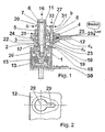
- Fig. 1 the structure of the device for the controlled storage of components is shown on a vibration damper, whose operation will be explained with reference to this illustration.
- the device comprises two clamping plates 3 and 4, between which a so-called holder 12, which is also referred to as a “bearing block”, attached (respectively clamped) is.
- This holder 12 is fixed to a (generally shown in FIG.) Component so that the load (s) and the mechanical vibrations on the holder 12 and other additional means (connecting and fixing elements of the device) is evenly distributed to a vibration damper (be ).
- the latter will absorb and balance the load (s) and body vibration (s) transmitted to it (of the holder-mounted component) via a damping body 15.
- the structure of the device is mainly by a lower clamping plate 3 (threaded plate), an upper clamping plate 4 (perforated plate), a nut 5 (lock nut), a fastening head screw 6, a (meaning screw-underlay) washer 7, a hollow body adjusting screw 2, a hollow body axial guide screw 8, an adjusting pin 9, a compression spring 10 and various fuse wire, which is guided by designated securing holes 11 in the respective screw head completes.
- the plate-like designed and component-connected holder 12 (bracket) is structurally designed and attached to the component so that the loads are evenly distributed, wherein in the disassembled state of the holder 12 access to the vibration damper 1 for its removal and installation in a confined space of the component - Depending on the design - also from the interior of the component to which the holder 12 are attached, is ensured.
- the vibration damper 1 is attached (expediently before the mounting of the holder 12) to its substructure (according to FIG. 1) or to a supporting body 14 (according to FIG. 5) fastened to the structure 30.
- the hollow body axial adjusting head screw 2 is screwed through the upper clamping plate 4 and the holder 12 in the lower clamping plate 3 (threaded plate) up to an example middle setting position and moved over the mounting terminal of the vibration damper 1, wherein the mobility of these clamping plates 3 and 4, the horizontal deviations be compensated.
- the mounting head screw 6, which is guided in the hollow body axial adjustment head screw 2, is initially screwed loosely into the vibration damper 1, whereby the mounting head screw 6 is positioned in its horizontal plane.
- the position of the holder 12 fixed to the component in the horizontal plane is determined.
- the hollow body adjusting head screw 2 is rotated in the lower clamping plate 3 (threaded plate) and thus adjusted the height of the component, which are balanced at the same time all vertical deviations of the vibration damper 1 with its base and the dimensional deviations of the component. This determines the position of the component in the vertical plane.
- a nut 5 on the hollow-body-axial adjusting head screw 2 is passed over the upper clamping plate 4 (perforated plate) with the lower clamping plate 3 (threaded plate) at a predetermined position Tightening torque.
- the mounting head screw 6 which is guided in the hollow body adjusting head screw 2, fixed to the vibration damper 1 with a predetermined torque.
- the clamped connections can not be solved, the mounting head screw 11, possibly also the hollow body adjusting head screw 2, the nut 5 (lock nut) and possibly also the hollow body axial guide screw 8 secured with a locking wire against rotation or loosening the screw (s) ,
- the storage on corresponding vibration dampers 1 can be construed constructively different depending on the requirements and taking into account the resulting in sum deviations. For the adjustment, attachment and securing of this storage on vibration dampers 1 you will be able to use commercially available tool in the rule.
- a device for controlled storage of a component on a vibration damper 1 which compensates dimensional deviations in three levels and produces a positive and non-positive connection.
- axial adjusting head screw 2 With the upper clamping plate 4 (perforated plate), with the lower clamping plate 3 (threaded plate) out, which is fixedly connected to the holder 12 (bearing block) of the component and itself move within a defined path in both horizontal axes and thus can be adjusted.
- the holder 12 By rotation of the hollow body axial adjusting head screw 2 in the lower clamping plate 3 (threaded plate) with-defined bolt length in the vertical axis (nraum) the holder 12 (bracket) and thus the component attached to it in the vertical plane is moved (lowered or raised) respectively set.
- the nut 5 (lock nut) is tightened after completion of the horizontal and vertical settings with a defined torque, thereby the form-fitting manner, the horizontal position of the holder 12 (holder-mounted component) and the vertical position of the holder 12 (the holder-mounted component) is fixed.
- the fastening head screw 6 is connected to the final attachment of the thus set holder 12 (the thus position-fixed component) with a predetermined torque on the hollow body axial adjusting head screw 2 with the vibration damper 1 positively.
- the adjusting pin 9 is guided by the hollow body axial guide screw 8 and in conjunction with the hollow body axial adjusting head screw 2, the setting on the (explained later) elements: "Kimme” and "grain” performed.
- To replace the bearing parts and / or the vibration damper 1 after loosening the mounting head screw 6 from the vibration damper 1 and the clamping plate countered nut 5 is relieved by unscrewing the Einstellkopfschraube 2 from the lower clamping plate 3 (threaded plate) of the holder 12 (the holder-mounted component). This allows the parts of the device to be removed and installed again in the reverse order.
- By fixing the hollow body axial guide screw head 8 a rotation during actuation of the hollow body axial adjusting head screw 2 is excluded.
- the lower and upper clamping plate 3 and 4 are parallel to the surface of a support surface 17 of the damping body 15, the position of which largely coincides with the base of the housing 13, arranged between the bearing surfaces 19 and 20 of the holder 12 is clamped.
- the clamping plates 3 and 4 and the holder 12 are each two holes which are arranged spaced along a longitudinal plate axis 21, except.
- a hollow axial adjustment head screw 2 is positioned, which is guided through a first hole 24 of the upper clamping plate 4.
- the screw thread of the adjusting head screw 2 is screwed to the first threaded hole 22 to a middle screw setting position of the lower clamping plate 3.
- a third threaded hole 26 is recessed in the support surface 17 of the damping body 15, in which a mounting head screw 6, guided by the cavity of the adjusting screw 2 is screwed.
- the latter is screwed so that the screw bolt end-side screw hollow cross-section of the adjusting head screw 2 is circumferentially fastened to the third threaded hole 26 on the support surface 17 of the damping body 15.
- a hollow body axial guide screw 8 is guided through a second hole 25 of the upper clamping plate 4, the screw thread is screwed to the second threaded hole 23 of the lower clamping plate 3.
- the screw head of the guide screw 8 is tightened against the upper clamping plate 4 with a defined screw torque.
- an adjusting pin 9 is guided axially movable, which is positioned at right angles to a support surface 18.
- the latter is arranged on the housing side and is a partial region of the top surface of the housing 13.
- the cross section of the pin bolt is then thickened (due to the clamping of the compression spring 10) bolt end side, so that the spring ends can press against this thickening and against the screw end of the guide screw 8.
- the bolt diameter d B of the thickening is smaller than the hole diameter d S of the upper clamping plate 4 in the region of the screw head of the guide screw 8 so that it is freely movable in the clamping plate 4 and thus also an additional clamping, in addition to the lock nut 5, allows.
- a measuring head with a rotationally symmetrical wedge-shaped recess (rear sight) is arranged.
- the damping body 15 the function of which comprises a plurality of elements which are not discussed further (for reasons) comprises - in addition to these further housing-internally arranged and functionally linked elements - the aforementioned damping body 15, which (functionally considered) an axially spring-back and spring-back element is. With these functionally linked elements, the damping is implemented by the vibration damper 1.
- the support surface 17 of the damping body 15 is located in parallel, as are the lower and upper clamping plate 3 and 4 and the latter clamped between the holders 12, which are also arranged in parallel, wherein the holder 12 is fixed to a right-angle member.
- the screw thread of the adjusting head screw 2 is screwed to the inner thread of the first threaded hole 22 of the lower clamping plate 3 to a middle screw setting position. If the screw head 21 of the adjusting head screw 2 is shaped to a measuring edge S tapered to the screw head circumference, and a measuring head with notch 27, which has a notch at the upper end of the pin bolt of the adjusting pin 9, whose recess is also parallel, the measuring edge S as a grain and the notch used as a rear sight, with which a visual adjustment mechanism is realized, with which the bearing of the component, which is mechanically connected to the holder 12, significantly on the alignment 31 between the sight and grain during different setting situations (according to Figures 3 to 6) is visually inspected.
- a second screw axis 18 of the guide screw 8 is screw axis parallel and definitely spaced from the first screw axis 16 of the adjusting head screw 2 is arranged.
- the cavity diameter d B in the region of the screw bolt of the guide screw 8 is larger than the bolt diameter d S (slot) of the guide screw 8 in the region of the screw head.
- the bolzenend workede diameter of the thickening of the adjusting pin 9 is to be smaller than the cavity diameter screw d S (threaded inside diameter of the lower clamping plate 3) in the region of the screw head of the guide screw 8 at any time, the guiding head screw 8 including the adjusting pin.
- Fig. 2 the mounting opening for the device for the controlled storage of components on a vibration damper in the holder 12 is shown, which is designed as a flat plate, in the profile cross section, a third hole 28 (circular hole) and an adjacent fourth hole 29 (slot ), whose concurrent to the circular hole extending perforation is directed to the center of the circular hole, is recessed, the hole recesses open into one another.
- the hole diameter of the circular hole is larger than the outer diameter of the adjusting head screw 2
- the hole diameter of the long hole is larger than the outer diameter of the guide screw 8.
- the outer diameter of the third hole 28 is significantly larger than the screw diameter of the adjusting head screw 2, so that the required setting is achieved, and formed as a slot fourth hole 29 in width slightly larger than the screw diameter of the guide screw 8 and also in length is large enough not to hinder the full freedom of movement of the adjusting head screw 2, and thus at the same time in the holder to be fastened 12 (before adjustment of the device) is movable and secured against rotation
- FIG. 3 shows the unloaded position of a device in a component connecting to the vibration damper 1, wherein a visible height difference SL is displayed between the sight and the grain.
- the setting of the device without height deviation is revealed via the adjusting pin 9.
- the setting of a structurally (for example +3 mm tolerance compensation) vertically raised device is shown in which after adjustment with the adjusting head 2, the tolerances of +3 mm were compensated.
- the setting of a structurally (for example, -3 mm tolerance compensation) vertically lowered device is shown in which after adjustment with the adjusting head screw 2, the slip deviation of -3 mm has been compensated. From these figures 3 to 6 it is easy to recognize the configuration (s) once in the unloaded state and three times in the loaded state.
Landscapes
- Engineering & Computer Science (AREA)
- General Engineering & Computer Science (AREA)
- Manufacturing & Machinery (AREA)
- Mechanical Engineering (AREA)
- Vibration Prevention Devices (AREA)
- Supporting Of Heads In Record-Carrier Devices (AREA)
- Cold Air Circulating Systems And Constructional Details In Refrigerators (AREA)
Abstract
Description
Die Erfindung bezieht sich auf eine Vorrichtung zur kontrollierten Lagerung von Bauteilen auf Schwingungsdämpfern, mit der Maßabweichungen eines gelagerten Bauteils in drei Ebenen durch einen Einstellmechanismus der Vorrichtung ausgeglichen und die Einsinktiefe in den Schwingungsdämpfern visuell angezeigt wird.The invention relates to a device for the controlled storage of components on vibration dampers, compensated with the dimensional variations of a stored component in three levels by an adjustment mechanism of the device and the sinking depth is visually displayed in the vibration.
Es sind formschlüssige und kraftschlüssige mechanische Lagerungen auf Schwingungsdämpfern bekannt, die ebenfalls Maßabweichungen ausgleichen, jedoch unter Verwendung von angepassten Profil-Unterlagen, bspw. von Shim -Blechen o.ä., und / oder durch den Einsatz zusätzlicher Verbindungselemente. Diese Maßabweichungen können auf konstruktiven Toleranzen beruhen und /oder auf anlagebedingte Toleranzen der Fertigungsmittel für die Herstellung der zu verbindenden Einzelteile zurückgehen. Ebenso sind Maßabweichungen aufgrund eines nachträglichen, materialbedingten Verzugs dieser gelagerten Bauteile und / oder des Unterbaus der Lagerung denkbar, wobei die Maßabweichungen ursächlich auch auf die eingesetzten Schwingungsdämpfer selbst zurückgehen können. Auch ist, bedingt durch die Verwendung von zusätzlichen losen Teilen bei derartigen Lagerungen, für die Montage ein erhöhter Raumbedarf (mehr Einbauraum) erforderlich. Wegen der zusätzlichen Einzelteile weisen diese Verbindungen auch ein höheres Gesamtgewicht auf. Derartige Verbindungen sind aufgrund der zusätzlichen Elemente kostenintensiver und erfordern einen höheren Zeitaufwand bei der Montage. Bedenkt man weiterhin, dass die beste Wirksamkeit eines Schwingungsdämpfers dann erreicht wird, wenn sich bei Nennlast die Einsinktiefe im optimalen Bereich der Kennlinie des Schwingungsdämpfers befindet, dann sind keine Lagerungen auf Schwingungsdämpfern bekannt, die eine Anzeige der aktuellen Einsinktiefe in das Dämpfungselement umsetzen. Dieser Umstand macht sich insbesondere bei einer schwer zugänglichen Einbauposition der installierten Schwingungsdämpfer nachteilig bemerkbar.There are known positive and non-positive mechanical bearings on vibration dampers, which also compensate for deviations, however, using adapted profile documents, for example. Shim sheets or the like, and / or through the use of additional fasteners. These deviations can be based on constructive tolerances and / or go back to plant-related tolerances of the manufacturing means for the production of the individual parts to be joined. Likewise, deviations due to a subsequent, material-related delay of these stored components and / or the substructure of the storage are conceivable, the deviations can be caused causally also on the vibration damper itself. Also, due to the use of additional loose parts in such bearings, an increased space requirement (more installation space) required for the assembly. Because of the additional items, these compounds also have a higher total weight. Such compounds are more expensive due to the additional elements and require a higher amount of time during assembly. Considering further that the best effectiveness of a vibration damper is achieved when at nominal load the sinking depth is in the optimum range of the characteristic of the shock absorber, then no bearings on vibration dampers are known to implement an indication of the current sinking depth in the damping element. This fact makes disadvantageous especially in a hard to reach installation position of the installed vibration damper.
Außerdem ist aus der Druckschrift: "DE 41 41 850 C2" ein elastisches Lagerelement bekannt, mit dem die Abstützung eines Bauteils gegenüber einem Fundament realisiert wird. Dieses Lagerelement besteht aus einem Lager-Unterteil, einer Lagerkappe und einem zwischen den beiden Teilen liegenden Elastomerblock. Das abzustützende Bauteil, beispielsweise ein (nach der Druckschrift vorgesehener) Motor- oder Getriebefuß, wird gegenüber der Lagerkappe verspannt. Zu diesem Zweck ist eine Zentral-Befestigungsschraube in ein Zwischenteil eingeschraubt, welches sich gegen die Lagerkappe abstützt. Zum Verspannen ist eine Mutter vorgesehen. Zwischen dem Bauteil und der Lagerkappe ist ein Höhenverstellungsteil angeordnet, welches sich in ein Unterteil und ein Oberteil gliedert. Das Oberteil kann mittels einem Gewinde durch Verdrehen gegenüber dem Unterteil in seiner Höhe verstellt werden. Dabei ist vorgesehen, dass jenes Höhenverstellungsteil aus dem mit der Lagerkappe fest verbundenen Unterteil und einem mittels dem Gewinde gegenüber dem Unterteil höhenverstellbaren Oberteil gebildet wird. Diese Maßnahme ist deswegen erforderlich, um beispielsweise eine Fluchtung einer (in der Figur der Druckschrift) nicht dargestellten Motorwelle mit Getriebeteilen zu gewährleisten.In addition, from the publication: "DE 41 41 850 C2" an elastic bearing element is known with which the support of a component is realized with respect to a foundation. This bearing element consists of a bearing base, a bearing cap and an elastomeric block lying between the two parts. The component to be supported, for example a motor or transmission foot (provided according to the publication), is braced against the bearing cap. For this purpose, a central fixing screw is screwed into an intermediate part, which is supported against the bearing cap. For clamping a nut is provided. Between the component and the bearing cap a height adjustment part is arranged, which is divided into a lower part and an upper part. The upper part can be adjusted in height by means of a thread by turning relative to the lower part. It is provided that that height adjustment part is formed from the fixedly connected to the bearing cap lower part and a height-adjustable by means of the thread relative to the lower part upper part. This measure is therefore necessary to ensure, for example, an alignment of a (not shown in the figure of the publication) motor shaft with gear parts.
Zur Überprüfung der Höhenlage des Bauteils weist die Zentral-Befestigungsschraube eine Zentralbohrung auf, durch die sich ein Gewindebolzen einführen lässt. Der Gewindebolzen weist an seinem oberen Ende eine Überwurfkappe auf, so dass zur variablen Festlegung eine Arretierung der Überwurfkappe gegenüber dem Gewindebolzen mit Hilfe einer selbstsichemden Sechskantmutter ausführbar wird. Hinzukommend ist vorgesehen, dass der Gewindebolzen in der Zentralbohrung sich in einer vorgegebenen Position durch eine Kugelarretierung arretieren lässt. Alternativ besteht auch die Möglichkeit, dass das Höhenverstellungsteil aus sogenannten Beilagscheiben gebildet wird, welche zwischen der Lagerkappe und dem Bauteil eingeschoben werden.To check the height of the component, the central fastening screw has a central bore, through which a threaded bolt can be inserted. The threaded bolt has at its upper end a cap, so that for variable fixing a locking of the cap over the threaded bolt by means of a self-locking hex nut is executable. In addition, it is provided that the threaded bolt in the central bore can be locked in a predetermined position by a ball lock. Alternatively, it is also possible that the height adjustment part is formed from so-called washers, which are inserted between the bearing cap and the component.
Dieses Lagerelement, bei dem die Notwendigkeit eines Kompensierens von Setzvorgängen eines Elastomerblocks, der bspw. zur Abfederung und Schwingungsdämpfung verwendet wird, problemlos erkannt wird, ohne dass dafür geeignete Messgeräte eingesetzt werden, wird aufgrund der Funktionen seiner Bauelemente kaum geeignet sein, bestehende Maßabweichungen eines gelagerten Bauteils in allen drei Ebenen innerhalb einem vordefinierten Einstellbereich auszugleichen. Die Kompensation wird nur mit Hilfe einer Höhenverstellung (Höhenjustierung) am Lagerelement umgesetzt, wobei deren Erfordernis ursächlich auf ein zeitbedingtes Absenken des Elastomerblocks zurückgehen wird, dessen Werkstoff mit einer dem zeitlichen Einfluss unterliegenden Formveränderung des Elastomerblocks korrelieren wird, weshalb ein Absenken jenes Elastomerblocks wohl kaum beeinflusst werden kann.This bearing element, in which the need to compensate for setting operations of an elastomeric block, which is used, for example, for cushioning and vibration damping, is easily detected without the use of suitable measuring devices will hardly be due to the functions of its components, existing deviations of a stored Compensate component in all three levels within a predefined setting range. The compensation is implemented only by means of a height adjustment (height adjustment) on the bearing element, the requirement of which will be due to a time-dependent lowering of the elastomer block, the material will correlate with a temporal influence underlying change in shape of the elastomer block, which is why a lowering of that elastomer block hardly influenced can be.
Demzufolge liegt der Erfindung die Aufgabe zugrunde, eine Vorrichtung zur kontrollierten Lagerung von Bauteilen auf Schwingungsdämpfern anzugeben, mit der bestehende Maßabweichungen eines dermaßen gelagerten Bauteiles in allen drei Ebenen innerhalb einem vordefinierten Einstellbereich ausgeglichen werden. Des weiteren soll mit dieser Vorrichtung ein rationeller Austausch des Schwingungsdämpfers ermöglicht werden, ohne dass das gelagerte Bauteil in seiner Position verändert wird. Gleichfalls soll ein visueller Justiermechanismus vorgesehen werden, um die optimale Einstellung des gelagerten Bauteils mit Hilfe der Vorrichtung auf der Kennlinie des Schwingungsdämpfers kontrollierbar sicherzustellen, ohne das ein Sichtkontakt zum (möglichenfalls außerhalb einer zugänglichen Einbauposition befindlichen) Schwingungsdämpfer erforderlich wird.Accordingly, the invention has for its object to provide a device for the controlled storage of components on vibration dampers, be compensated with the existing dimensional deviations of a so-mounted component in all three levels within a predefined setting range. Furthermore, a rational replacement of the vibration damper should be made possible with this device, without the stored component is changed in position. Likewise, a visual adjustment mechanism is provided to controllably ensure the optimum adjustment of the mounted component by means of the device on the characteristic of the vibration damper, without requiring visual contact with the (possibly located outside an accessible installation position) vibration damper.
Diese Aufgabe wird durch die im Anspruch 1 angegebenen Maßnahmen gelöst. In den weiteren Ansprüchen werden zweckmäßige Ausgestaltungen und Weiterbildungen dieser Maßnahmen angegeben.This object is achieved by the measures specified in claim 1. In the further claims expedient refinements and developments of these measures are given.
Die Erfindung ist in einem Ausführungsbeispiel anhand der beigefügten Zeichnungen näher beschrieben.
Dazu zeigen die
- Fig. 1
- eine Vorrichtung zur kontrollierten Lagerung von Bauteilen auf einem Schwingungsdämpfer;
- Fig. 2
- die Aufnahme im bauteilebefestigten Halter der Vorrichtung nach Fig. 1;
- Fig. 3
- die unbelastete Normaleinstellung einer Vorrichtung mit einem auf dem Schwingungsdämpfer lagernden Bauteil (visuelle Höhen-Anzeige);
- Fig. 4
- die mit einem Justierstift sichtbare Einstellung der Vorrichtung nach Fig. 3 ohne Maßabweichung der Auflage, wobei der Justiermechanismus sich in seiner neutralen Position befindet und nicht betätigt wurde;
- Fig. 5
- die Einstellung einer strukturell vertikal angehobenen Vorrichtung nach Fig. 4 mit einer Maßabweichung der strukturellen Auflage nach oben, welche durch den Justiermechanismus ausgeglichen wurde;
- Fig. 6
- die Einstellung einer strukturell vertikal abgesenkten Vorrichtung nach der Fig. 4 mit einer Maßabweichung der strukturellen Auflage nach unten, welche durch den Justiermechanismus ausgeglichen wurde.
To show the
- Fig. 1
- a device for the controlled storage of components on a vibration damper;
- Fig. 2
- the inclusion in the component-mounted holder of the device of FIG. 1;
- Fig. 3
- the unloaded normal setting of a device with a bearing on the vibration damper component (visual height indicator);
- Fig. 4
- the setting of the device according to FIG. 3, visible with an adjusting pin, without deviation of the bearing, wherein the adjusting mechanism is in its neutral position and has not been actuated;
- Fig. 5
- the adjustment of a structurally vertically raised device of Figure 4 with a dimensional deviation of the structural support upward, which has been compensated by the adjustment mechanism;
- Fig. 6
- the setting of a structurally vertically lowered device of FIG. 4 with a dimensional deviation of the structural support down, which has been compensated by the adjustment mechanism.
In der Fig. 1 wird der Aufbau der Vorrichtung zur kontrollierten Lagerung von Bauteilen auf einem Schwingungsdämpfer dargestellt, deren Wirkungsweise anhand dieser Darstellung erläutert wird. Die Vorrichtung umfasst zwei Klemmplatten 3 und 4, zwischen denen ein sogenannter Halter 12, der auch als "Lagerbock" bezeichnet wird, befestigt (respektive geklemmt) ist. Dieser Halter 12 ist an einem (figurlich allgemein dargestellten) Bauteil dermaßen befestigt, dass die Last(en) und die mechanischen Schwingungen über den Halter 12 und weitere zusätzliche Mittel (Verbindungs- und Befestigungselemente der Vorrichtung) auf einen Schwingungsdämpfer 1 gleichmäßig verteilt wird (werden). Letzterer wird über einen Dämpfungskörper 15 die auf ihn übertragene(n) Last(en) und , Körper-Schwingung(en) (des halterbefestigten Bauteils) aufnehmen und ausgleichen.In Fig. 1, the structure of the device for the controlled storage of components is shown on a vibration damper, whose operation will be explained with reference to this illustration. The device comprises two
Der Aufbau der Vorrichtung wird in der Hauptsache durch eine untere Klemmplatte 3 (Gewindeplatte), eine obere Klemmplatte 4 (Lochplatte), eine Schraubenmutter 5 (Kontermutter), eine Befestigungskopfschraube 6, eine (sinnvollerweise schraubenkopfunterlegte) Unterlegscheibe 7, eine hohlkörperaxiale Einstellschraube 2, eine hohlkörperaxiale Führungskopfschraube 8, einen Justierstift 9, eine Druckfeder 10 und diversen Sicherungsdraht, der durch bezeichnete Sicherungslöcher 11 im betreffenden Schraubenkopf geführt wird, komplettiert.The structure of the device is mainly by a lower clamping plate 3 (threaded plate), an upper clamping plate 4 (perforated plate), a nut 5 (lock nut), a fastening head screw 6, a (meaning screw-underlay) washer 7, a hollow
Um das Verständnis für die späteren Erläuterungen zu nähren, wird die betreffende Vorrichtung folgendermaßen angeben. Der plattenartig gestaltete und bauteilverbundene Halter 12 (Lagerbock) ist konstruktiv so gestaltet und am Bauteil so befestigt, dass die Lasten gleichmäßig verteilt werden, wobei im ausgebauten Zustand des Halters 12 der Zugang zum Schwingungsdämpfer 1 für dessen Aus- und Einbau auf beengtem Lagerraum des Bauteils - je nach Bauart - auch aus dem Innenraum des Bauteils, an welchem die Halter 12 befestigt sind, sichergestellt wird.To aid understanding of the later explanations, the subject device will be indicated as follows. The plate-like designed and component-connected holder 12 (bracket) is structurally designed and attached to the component so that the loads are evenly distributed, wherein in the disassembled state of the
Der Schwingungsdämpfer 1 wird (zweckmäßiger Weise vor der Montage des Halters 12) an seinem Unterbau (nach Fig. 1) oder einem auf der Struktur 30 befestigten Stützkörper 14 (nach Fig. 5)] befestigt.The vibration damper 1 is attached (expediently before the mounting of the holder 12) to its substructure (according to FIG. 1) or to a supporting body 14 (according to FIG. 5) fastened to the
Die hohlkörperaxiale Einstellkopfschraube 2 wird durch die obere Klemmplatte 4 und den Halter 12 in die untere Klemmplatte 3 (Gewindeplatte) bis zu einer beispielsweise mittleren Einstellungsposition eingeschraubt und über den Befestigungsanschluss des Schwingungsdämpfers 1 bewegt, wobei durch die Beweglichkeit dieser Klemmplatten 3 und 4 die horizontalen Maßabweichungen ausgeglichen werden. Die Befestigungskopfschraube 6, welche in der hohlkörperaxialen Einstellkopfschraube 2 geführt ist, wird in den Schwingungsdämpfer 1 vorerst lose eingeschraubt, womit die Befestigungskopfschraube 6 in ihrer horizontalen Ebene positioniert ist. Hiermit ist die Position des am Halter 12 befestigten Bauteils in der horizontalen Ebene bestimmt. Nachdem alle Lagerungen des Bauteils horizontal ausgerichtet sind, wird die hohlkörperaxiale Einstellkopfschraube 2 in der unteren Klemmplatte 3 (Gewindeplatte) gedreht und damit die Höhe des Bauteils eingestellt, womit gleichzeitig alle vertikalen Maßabweichungen des Schwingungsdämpfers 1 mit seinem Unterbau und die Maßabweichungen des Bauteils ausgeglichen sind. Hiermit ist die Position des Bauteils in der vertikalen Ebene bestimmt. Nachdem die endgültige Position des [über den Halter 12 (Lagerbock)] klemmplattenbefestigten Bauteils erreicht ist, wird eine Schraubenmutter 5 (Kontermutter) an der hohlkörperaxialen Einstellkopfschraube 2 über die obere Klemmplatte 4 (Lochplatte) mit der unteren Klemmplatte 3 (Gewindeplatte) mit einem vorgegebenen SchraubenDrehmoment befestigt. Danach wird die Befestigungskopfschraube 6, welche in der hohlkörperaxialen Einstellkopfschraube 2 geführt ist, mit einem vorgegebenen Drehmoment an dem Schwingungsdämpfer 1 befestigt. Damit die eingespannten Verbindungen sich nicht lösen können, werden die Befestigungskopfschraube 11, ggf. auch die hohlkörperaxiale Einstellkopfschraube 2, die Schraubenmutter 5 (Kontermutter) und ggf. auch die hohlkörperaxiale Führungskopfschraube 8 mit einem Sicherungsdraht gegen Verdrehung bzw. Lösen der Schraubverbindung(en) gesichert. Die Lagerung auf entsprechenden Schwingungsdämpfern 1 kann je nach Anforderung und unter Berücksichtigung der sich in der Summe ergebenden auszugleichenden Maßabweichungen konstruktiv unterschiedlich ausgelegt werden. Für die Einstellung, die Befestigung und die Sicherung dieser Lagerung auf Schwingungsdämpfern 1 wird man in der Regel handelsübliches Werkzeug verwenden können.The hollow body axial adjusting
Demnach wird eine Vorrichtung zur kontrollierten Lagerung von einem Bauteil auf einem Schwingungsdämpfer 1 angegeben, die Maßabweichungen in drei Ebenen ausgleicht und eine form- und kraftschlüssige Verbindung herstellt. Für die Einstellung des halterbefestigten Bauteils in der horizontalen Ebene wird die erwähnte hohlkörperaxiale Einstellkopfschraube 2 mit der oberen Klemmplatte 4 (Lochplatte), mit der unteren Klemmplatte 3 (Gewindeplatte) geführt, die fest mit dem Halter 12 (Lagerbock) des Bauteils verbundenen ist und sich innerhalb eines definierten Weges in beiden horizontalen Achsen verschieben und damit einstellen lässt.Accordingly, a device for controlled storage of a component on a vibration damper 1 is specified, which compensates dimensional deviations in three levels and produces a positive and non-positive connection. For the setting of the holder-mounted component in the horizontal plane mentioned hollow body axial adjusting
Durch Drehung der hohlkörperaxialen Einstellkopfschraube 2 in der unteren Klemmplatte 3 (Gewindeplatte) mit-definierter Schraubenbolzen-Länge in der vertikalen Achse(nrichtung) wird der Halter 12 (Lagerbock) und damit das ihm befestigte Bauteil in der vertikalen Ebene verschoben (abgesenkt oder angehoben) respektive eingestellt. Die Schraubenmutter 5 (Kontermutter) wird nach Abschluss der horizontalen und vertikalen Einstellungen mit einem definierten Drehmoment angezogen, wodurch damit die horizontale Lage des Halters 12 (halterbefestigten Bauteils) kraftschlüssig und die vertikale Lage des Halters 12 (des halterbefestigten Bauteils) formschlüssig fixiert ist. Die Befestigungskopfschraube 6 wird zur abschließenden Befestigung des dermaßen eingestellten Halters 12 (des dermaßen lagefixierten Bauteils) mit einem vorgegebenen Drehmoment über die hohlkörperaxiale Einstellkopfschraube 2 mit dem Schwingungsdämpfer 1 formschlüssig verbunden. Der Justierstift 9 wird durch die hohlkörperaxiale Führungsschraube 8 geführt und in Verbindung mit der hohlkörperaxialen Einstellkopfschraube 2 die Einstellung über die (später erläuterten) Elemente: "Kimme" und "Korn" durchgeführt. Zum Austausch der Lagerteile und / oder des Schwingungsdämpfers 1 nach dem Lösen der Befestigungskopfschraube 6 aus dem Schwingungsdämpfer 1 und der klemmplattengekonterten Schraubenmutter 5 wird durch das Herausdrehen der Einstellkopfschraube 2 aus der unteren Klemmplatte 3 (Gewindeplatte) der Halter 12 (das halterbefestigte Bauteil) entlastet. Damit lassen sich die Teile der Vorrichtung ausbauen und in umgekehrter Reihenfolge wieder einbauen. Durch die Befestigung der hohlkörperaxialen Führungskopfschraube 8 wird eine Verdrehung beim Betätigen der hohlkörperaxialen Einstellkopfschraube 2 ausgeschlossen.By rotation of the hollow body axial adjusting
Diesen vorangestellten Bemerkungen wird der Vollständigkeit halber ergänzt, dass das Gehäuse 13 des Schwingungsdämpfers 1 (nach dem Beispiel der Fig. 1) mit der Grundfläche an einer Struktur 30 befestigt ist. Gehäuseintern ist diesem Schwingungsdämpfer 1 der bezeichnete Dämpfungskörper 15 angeordnet, der die auf ihn übertragenen mechanischen Belastungen [die übertragen Last(en) des halterbefestigten Bauteils und die Schwingungen (fremdübertragene mechanische Schwingungen und Eigenschwingungen des Bauteils)] aufnimmt. Mit diesem Dämpfungskörper 15 ist (entsprechend dem Kraftfluß der übertragenen Bauteil-Last) der erwähnte Halter 12 über weitere Verbindungs- und Befestigungsmittel der Vorrichtung mechanisch verbunden. So wird beispielsweise der Halter 12 - nach dem Vorbild der Figuren 1, 3, 4, 5 und 6 - an einem zu lagernden Bauteil befestigt, dessen Last über den Halter 12 und die angegebenen zusätzlichen Mittel der Vorrichtung auf den Schwingungsdämpfer 1 und in Folge auf seinen Unterbau (Struktur 30) übertragen wird.For the sake of completeness, these preceding remarks supplement the fact that the
Die untere und obere Klemmplatte 3 und 4 sind flächenparallel einer Auflagefläche 17 des Dämpfungskörpers 15, deren Lage weitestgehend mit der Grundfläche des Gehäuses 13 übereinstimmt, angeordnet, zwischen deren Auflageflächen 19 und 20 der Halter 12 geklemmt ist. Den Klemmplatten 3 und 4 sowie dem Halter 12 sind jeweils zwei Löcher, die entlang einer Plattenlängsachse 21 beabstandet angeordnet sind, ausgenommen.The lower and
Diese Löcher des vorbeschriebenen Klemmplatten-Halter-Aufbaus sind den beiden Klemmplatten 3 und 4 kongruent ausgenommen, die mit denjenigen Löchern des Halters 12 übereinanderliegend angeordnet sind, wobei die Löcher der unteren Klemmplatte 3 als ein erstes und zweites Gewindeloch 22 und 23 ausgebildet sind. So wird vorzugsweise - vorgreifend der Ausführungen hinsichtlich der Fig. 2 - (auch aus später erwähnten Gründen) vorgesehen, dass ein drittes Loch 28 des Halters 12 als Kreisloch und ein viertes Loch 29 des Halters 12 als Langloch ausgebildet ist, wobei deren Lochflächen durchgehend verbunden sind.These holes of the above-described clamp-holder structure are congruent except for the two
Im rechten Winkel stehend auf der Auflagefläche 17 des Dämpfungskörper 15 ist eine hohlkörperaxiale Einstellkopfschraube 2 positioniert, die durch ein erstes Loch 24 der oberen Klemmplatte 4 geführt ist. Das Schraubengewinde der Einstellkopfschraube 2 ist dem ersten Gewindeloch 22 bis zu einer mittleren Schraubeneinstellposition der unteren Klemmplatte 3 geschraubt.At a right angle on the
In der Verlängerung einer ersten Schraubenachse 16 der Einstellkopfschraube 2 ist in der Auflagefläche 17 des Dämpfungskörpers 15 ein drittes Gewindeloch 26 eingelassen, in welchem eine Befestigungskopfschraube 6, geführt durch den Hohlraum der Einstellschraube 2 eingeschraubt ist. Letztere ist dermaßen geschraubt, dass der schraubenbolzenendseitige Schraubenhohlquerschnitt der Einstellkopfschraube 2 umfänglich dem dritten Gewindeloch 26 auf der Auflagefläche 17 des Dämpfungskörpers 15 befestigt ist.In the extension of a
Weiter ist dem Schraubenbolzen der gewindelochfixierten Einstellkopfschraube 2 oberhalb der oberen Klemmplatte 4 eine Schraubenmutter 5 aufgeschraubt, die mit einem definierten Schraubendrehmoment gegen die obere Klemmplatte 4 angezogen wird, wodurch die Lage des Halters 12 horizontal kraftschlüssig und die Lage des halterbefestigten Bauteils vertikal formschlüssig fixiert wird.Next, the screw of the threaded hole fixed adjusting
Außerdem ist durch ein zweites Loch 25 der oberen Klemmplatte 4 eine hohlkörperaxiale Führungskopfschraube 8 geführt, deren Schraubengewinde dem zweiten Gewindeloch 23 der unteren Klemmplatte 3 geschraubt ist. Der Schraubenkopf der Führungskopfschraube 8 wird mit einem definierten Schraubendrehmoment gegen die oberen Klemmplatte 4 angezogen.In addition, a hollow body
Durch den Hohlraum der Führungskopfschraube 8 ist ein Justierstift 9 achsenbeweglich geführt, der im rechten Winkel stehend auf einer Stützfläche 18 positioniert ist. Letztere ist gehäuserandseitlich angeordnet und ist ein Teilbereich der Deckfläche des Gehäuses 13.Through the cavity of the
Am Stiftbolzen des Justierstiftes 9 ist (nach dem Vorbild der Fig. 1) bolzenbeweglich eine Druckfeder 10 angeordnet.On pin bolt of the adjusting
Der Querschnitt des Stiftbolzens ist dann (wegen der Einspannung der Druckfeder 10) bolzenendseitig verdickt, so dass die Federenden gegen diese Verdickung und gegen das Schraubenende der Führungskopfschraube 8 drücken können. Der Schraubenbolzen-Durchmesser dB der Verdickung ist kleiner als der Loch-Durchmesser dS der oberen Klemmplatte 4 im Bereich des Schraubenkopfes der Führungskopfschraube 8, damit dieser frei beweglich in der Klemmplatte 4 ist und somit auch eine zusätzliche Klemmung, ergänzend zur Kontermutter 5, ermöglicht. Dem wird ergänzt, dass (nach der Fig. 1) am oberen Ende des Justierstiftes 9 ein Messkopf mit einer rotationssymmetrisch keilförmigen Ausdrehung (Kimme) angeordnet ist.The cross section of the pin bolt is then thickened (due to the clamping of the compression spring 10) bolt end side, so that the spring ends can press against this thickening and against the screw end of the
Um den beabsichtigten Zweck der Kontrolle der Lagerung des Bauteils auf einem Schwingungsdämpfer umzusetzen, ist eine Flucht 31 zwischen dem Messkopf (Kimme) des Justierstiftes 9 und der Messunterkante des Schraubenkopfes der Einstellkopfschraube 2 (Korn) für die visuelle Kontrolle der optimal mechanischen Belastung des Bauteils auf den Dämpfungskörper 15 des Schwingungsdämpfers 1 ermöglicht, die auch als visueller Justiermechanismus der Vorrichtung angesehen werden kann. Diesen Ausführungen wird hinzu gefügt, dass der Außendurchmesser des Schraubenbolzens der Einstellkopfschraube 2 größer dem Außendurchmesser der Führungskopfschraube 8 ist.In order to implement the intended purpose of controlling the mounting of the component on a vibration damper, there is an
Der Dämpfungskörper 15, dessen Funktion mehrere Elemente umfasst, auf die (aus Gründen) nicht näher eingegangen wird, umfasst - neben diesen weiteren gehäuseintern angeordneten und funktionell verknüpften Elemente - den erwähnten Dämpfungskörper 15, der (funktionell betrachtet) ein axial einfeder- und zurückfederndes Element ist. Mit diesen funktionell verknüpften Elementen wird die Dämpfung durch den Schwingungsdämpfer 1 umgesetzt. Die Auflagefläche 17 des Dämpfungskörpers 15 ist parallel gelegen, ebenso wie die untere und obere Klemmplatte 3 und 4 sowie der zwischen letzteren eingeklemmte Halter 12, die auch parallel angeordnet sind, wobei der Halter 12 ist an einem im rechten Winkel lastenden Bauteil befestigt ist. Das Schraubengewinde der Einstellkopfschraube 2 ist dem Innengewinde des ersten Gewindeloches 22 der unteren Klemmplatte 3 bis zu einer mittleren Schraubeneinstellposition geschraubt. Sofern der Schraubenkopf 21 der Einstellkopfschraube 2 zu einer dem Schraubenkopfumfang zulaufenden Messkante S geformt ist, und einem Messkopf mit Kerbe 27, dem am oberen Ende des Stiftbolzens des Justierstiftes 9 eine Kerbe eingearbeitet ist, dessen Vertiefung ebenfalls parallel ist, wird die Messkante S als Korn und die Kerbe als Kimme benutzt, mit denen ein visueller Justiermechanismus realisiert ist, mit dem die Lagerung des Bauteils, das dem Halter 12 mechanisch verbunden ist, maßgeblich über die Flucht 31 zwischen Kimme und Korn während unterschiedlicher Einstellsituationen (nach den Figuren 3 bis 6) visuell kontrolliert wird. Ferner ist eine zweite Schraubenachse 18 der Führungskopfschraube 8 schraubenachsenparallel und definitiv beabstandet der ersten Schraubenachse 16 der Einstellkopfschraube 2 angeordnet. Dabei ist der Hohlraum-Durchmesser dB im Bereich des Schraubenbolzens der Führungskopfschraube 8 größer dem Schraubenbolzen-Durchmesser dS (Langloch) der Führungskopfschraube 8 im Bereich des Schraubenkopfes ausgeführt.The damping
Der bolzenendseitige Durchmesser der Verdickung des Justierstiftes 9 ist kleiner dem Hohlraum-Durchmesser dS (Gewinde-Innendurchmesser der unteren Klemmplatte 3) im Bereich des Schraubenkopfes der Führungsschraube 8, um jederzeit die Führungskopfschraube 8 einschließlich des Justierstiftes 9 einschrauben zu können.The bolzenendseitige diameter of the thickening of the adjusting
Femer sind alle bewegten Schraubenverbindungen durch einen Sicherungsdraht gegen unbeabsichtigtes Lösen formschlüssig verbunden.Furthermore, all moving screw connections are positively connected by a safety wire against unintentional loosening.
In der Fig. 2 wird die Befestigungsöffnung für die Vorrichtung zur kontrollierten Lagerung von Bauteilen auf einem Schwingungsdämpfer in den Halter 12 dargestellt, der als ebene Platte ausgeführt ist, in deren Profilquerschnitt ein drittes Loch 28 (Kreisloch) und ein nebengelegenes viertes Loch 29 (Langloch), dessen gleichlaufend zum Kreisloch verlaufende Durchlochung zum Zentrum des Kreisloches gerichtet ist, ausgespart ist, wobei die Lochaussparungen ineinander einmünden. Der Lochdurchmesser des Kreisloches ist größer als der Außendurchmesser der Einstellkopfschraube 2 und der Lochdurchmesser des Langlochs ist größer als der Außendurchmesser der Führungskopfschraube 8.In Fig. 2, the mounting opening for the device for the controlled storage of components on a vibration damper in the
Man kann davon ausgehen, dass der Außendurchmesser des dritten Loches 28 deutlich größer ist als der Schraubendurchmesser der Einstellkopfschraube 2, damit die geforderte Einstellung erreicht wird, und das als Langloch ausgebildete vierte Loch 29 in der Breite etwas größer als der Schraubendurchmesser der Führungskopfschraube 8 sowie auch in der Länge groß genug ist, um die volle Bewegungsfreiheit der Einstellkopfschraube 2 nicht zu behindern, und damit gleichzeitig in dem zu befestigenden Halter 12 (vor geschehener Einstellung der Vorrichtung) beweglich und gegen Verdrehen gesichert istIt can be assumed that the outer diameter of the
In den Figuren 3 bis 6 werden vier Situationen dargestellt, die einmal den unbelasteten Zustand und in den drei anderen Situationen jeweils den belasteten Zustand zeigen, wobei die belasteten Zustände beispielsweise die maximale, die minimale und die neutrale Toleranzabweichung der Befestigungspunkte, auf welchen die Schwingungsdämpfer positioniert sind, in der Höhe wiedergeben. Aus diesen Prinzipdarstellungen wird ersichtlich, dass bei einer unterschiedlichen Bauteiltoleranz eines halterbefestigten Bauteils, das auf dem Schwingungsdämpfer 1 lastet, mittels der Einstellkopfschraube 2 die Flucht 31 zwischen dem Justierstift 9 und der Einstellkopfaube 2 durch die Veränderung der Eindrücktiefe in den Schwingungsdämpfer 1 (in den Dämpfungskörper 15) eingestellt werden kann. Aus diesen Darstellungen erkennt man, dass
- a) bei einem unbelasteten Schwingungsdämpfer (auch "Shock Mount" genannt) der Justierstift 9 und damit der Messkopf 27 unterhalb der Schrauben-Messkante liegt;
- b) bei einer Belastung über die Auflagekonsole (Brackets) die
Einstellkopfschraube 2 über den Dämpfungskörper 15 (gewissermaßen= in den "Shock Mount" eintaucht und um den selben Weg derJustierstift 9 sich relativ vertikal in Richtung der Schrauben-Messkante bewegt; - c) bei unterschiedlichen Bauteiltoleranzen mit
Hilfe der Einstellkopfschraube 2der Justierstift 9 immer mit der Schrauben-Meßkante fluchtet, wenn die richtige Belastung erreicht wird; - d) die Länge des Justierstiftes 9 grundsätzlich nach einer vorgegebenen Last bestimmt wird.
- a) at an unloaded vibration damper (also called "shock mount" called) the
alignment pin 9 and thus the measuringhead 27 is below the screw-measuring edge; - b) at a load on the support bracket (brackets) the adjusting
head screw 2 on the damping body 15 (to a certain extent = immersed in the "shock mount" and about the same way thealignment pin 9 moves relatively vertically in the direction of the screw-measuring edge; - c) at different component tolerances by means of the adjusting
head screw 2 of thealignment pin 9 is always aligned with the screw-measuring edge, if the correct load is achieved; - d) the length of the adjusting
pin 9 is always determined according to a predetermined load.
Hierzu wird in der Fig. 3 die unbelastete Stellung einer Vorrichtung bei einem mit dem Schwingungsdämpfer 1 verbindenden Bauteil gezeigt, wobei zwischen Kimme und Korn ein sichtbarer Höhenunterschied SL angezeigt wird. In der Fig. 4 wird über den Justierstift 9 die Einstellung der Vorrichtung ohne Höhen-Abweichung offenbart. Mit der Fig. 5 wird die Einstellung einer strukturell (beispielsweise +3 mm Toleranzausgleich) vertikal angehobenen Vorrichtung gezeigt, bei welcher nach der Justierung mit der Einstellkopfschraube 2 die Toleranzen von +3 mm ausgeglichen wurden. Mit der Fig. 6 wird die Einstellung einer strukturell (beispielsweise -3 mm Toleranzausgleich) vertikal abgesenkten Vorrichtung gezeigt, bei welcher nach der Justierung mit der Einstellkopfschraube 2 die Schlupf-Abweichung von -3 mm ausgeglichen wurde. Aus diesen Figuren 3 bis 6 kann man unschwer die Konfiguration(en) einmal im unbelasteten Zustand und dreimal im belasteten Zustand erkennen.For this purpose, FIG. 3 shows the unloaded position of a device in a component connecting to the vibration damper 1, wherein a visible height difference SL is displayed between the sight and the grain. In FIG. 4, the setting of the device without height deviation is revealed via the adjusting
- 11
- Schwingungsdämpfervibration
- 22
- Einstellkopfschraube, hohlkörperaxialAdjusting head screw, hollow body axial
- 33
- untere Klemmplatte (Gewindeplatte)lower clamping plate (threaded plate)
- 44
- obere Klemmplatte (Lochplatte)upper clamping plate (perforated plate)
- 55
- Schraubenmutter (Kontermutter)Nut (lock nut)
- 66
- BefestigungskopfschraubeFixing head screw
- 77
- Unterlegscheibewasher
- 88th
- FührungskopfschraubeGuiding head screw
- 99
- Justierstiftadjusting pin
- 1010
- Druckfedercompression spring
- 1111
- Sicherungsloch (für Sicherungsdraht)Lock hole (for security wire)
- 1212
- Halter (ebene Platte am Bauteil)Holder (flat plate on component)
- 1313
- Gehäuse (des Schwingungsdämpfers 1)Housing (of the vibration damper 1)
- 1414
- Stützkörpersupport body
- 1515
- Dämpfungskörper (des Schwingungsdämpfers 1)Damping body (of the vibration damper 1)
- 1616
- erste Schraubenachse (der Einstellkopfschraube 2)first screw axis (the adjusting head screw 2)
- 1717
- ebene Auflagefläche (des Dämpfungskörpers 15)level bearing surface (of the damping body 15)
- 1818
- Stützfläche (randseitlicher Teilbereich der Gehäuse-Deckfläche)Support surface (peripheral part of the housing top surface)
- 1919
- Stützfuß (des Justierstiftes 9)Support foot (of adjusting pin 9)
- 2020
- Schraubenkopf (der Einstellkopfschraube 2)Screw head (adjusting head screw 2)
- 2121
- Profillängsachse (Halter- oder Plattenlängsachse)Profile longitudinal axis (holder or plate longitudinal axis)
- 2222
- erstes Gewindeloch (der unteren Klemmplatte 3)first threaded hole (the lower clamping plate 3)
- 2323
- zweites Gewindeloch (der unteren Klemmplatte 3)second threaded hole (the lower clamping plate 3)
- 2424
- erstes Loch (der oberen Klemmplatte 4)first hole (the upper clamping plate 4)
- 2525
- zweites Loch (der oberen Klemmplatte 4)second hole (the upper clamping plate 4)
- 2626
- drittes Gewindeloch (des Dämpfungskörpers 15)third threaded hole (of the damping body 15)
- 2727
- Messkopf (des Justierstiftes 9)Measuring head (of the adjusting pin 9)
- 2828
- drittes Loch; Kreisloch (des Halters 12)third hole; Circular hole (of the holder 12)
- 2929
- viertes Loch; Langloch (des Halters 12)fourth hole; Slot (of the holder 12)
- 3030
- Struktur (Auflage des Schwingungsdämpfers)Structure (bearing of the vibration damper)
- 3131
- Flucht (visuelle Messlinie)Escape (visual measurement line)
- 3232
- zweite Schraubenachse (der Einstellkopfschraube 8)second screw axis (the adjusting head screw 8)
- SS
- Messkante (des spitzzulaufenden Schraubenkopfes der Einstellkopfschraube 2)Measuring edge (of the pointed screw head of the adjusting head screw 2)
- SLSL
- sichtbarer Höhenunterschied (maßlicher Abstand)visible height difference (measured distance)
- dB d B
- Durchmesser des Bolzens der Führungskopfschraube 8)Diameter of the bolt of the pilot head screw 8)
- dS d S
- Hohlraum-Durchmesser (im Bereich des Schraubenkopfes der Führungskopfschraube 8)Cavity diameter (in the region of the screw head of the guide screw 8)
Claims (24)
- Device for providing a controlled mounting for components, incorporating a vibration damper (1), the housing (13) of which can be secured to a structure (30), and a damping body (15) is disposed inside the housing to absorb the mechanical loads and vibrations transmitted to it from or on a component to which a holder (12) can be secured, which holder (12) transmits the loads of the component via other inter-connected connecting and fixing elements to the vibration damper (1), characterised in that, disposed surface-parallel with a support surface (17) of the damping body (15) are a bottom and a top clamping plate (3, 4), between which the holder (12) is clamped, and a hollow-body axial adjusting head screw (2) positioned on the support surface (17) at a right angle is inserted through holes of this clamping plates-holder assembly disposed one above the other, of which one hole assigned to the bottom clamping plate (3) is provided in the form of a first threaded hole (22) into which the adjusting head screw (2) is screwed as far as a defined screw setting position, and, inserted through the screw cavity of the adjusting head screw (2) oriented axially along a first screw axis (16), is a fixing head screw (6), which is positioned in and screwed into a third threaded hole (26) of the damping body (15) constituting an extension of the first screw axis (16), and a nut (5) is screwed onto the bottom end of a screw head (20) of the adjusting head screw (2) which is tightened down on the top clamping plate (4), and a hollow-body axial guiding head screw (8) is inserted parallel with and at a distance from the first screw axis (16) through other holes of the clamping plates-holder assembly disposed one above the other, of which another hole assigned to the bottom clamping plate (3) is provided in the form of a second threaded hole (23) into which is screwed the guiding head screw (8), the screw head of which is tightened down against the top clamping plate (4), and, inserted through the screw cavity of the guiding head screw (8) oriented axially along a second screw axis (32), is an adjusting pin (9) which is positioned laterally at the housing periphery at a right angle and axially freely displaceable on a support surface (18) constituting a part-region of the cover surface of the housing (13), which adjusting pin (9) has on the oppositely lying pin end a measuring head (27) which can be placed flush with the oppositely disposed measuring bottom edge of the screw head of the adjusting head screw (2), thereby providing a visual adjusting mechanism.
- Device as claimed in claim 1, characterised in that two respective holes spaced at a distance apart and lying one above the other are cut out from the holder (12) and the two clamping plates (3, 4) along a profile longitudinal axis (21), the holes of the clamping plates (3, 4) being disposed congruently, and the holes of the bottom clamping plate (3) are provided in the form of threaded holes (22, 23).
- Device as claimed in one of claims 1 or 2, characterised in that the adjusting head screw (2) is inserted through a first hole (24) of the top clamping plate (4) and a third hole (28) of the holder (12), the screw thread of which is screwed into the first threaded hole (22) of the bottom clamping plate (3).
- Device as claimed in claim 1, characterised in that the fixing head screw (6) is positioned on the support surface (17) of the damping body (15) in such a way that the screw cavity cross-section of the adjusting screw (2) at the screw bolt end is positioned surrounding the periphery of the third threaded hole (26) of the damping body (15).
- Device as claimed in claim 1, characterised in that, due to the screw connection of the nut (5) which is tightened down on the top clamping plate (4) with a defined screw torque, a non-positive connection of the holder (12) is obtained when the component secured by the holder is in the planar position and a positive connection is obtained in the position at a right angle thereto.
- Device as claimed in claim 1, characterised in that the guiding head screw (8) is inserted through a second hole (25) of the top clamping plate (4) and a fourth hole (29) of the holder (12) provided in the form of an elongate hole, the screw thread of which is screwed into the second threaded hole (23) of the bottom clamping plate (3).
- Device as claimed in claim 1, characterised in that the external diameter of the screw bolt of the adjusting head screw (2) is bigger than that of the guiding head screw (8).
- Device as claimed in one of claims 1 or 2, characterised in that the holder (12) is provided in the form of a flat plate, from the profile cross-section of which the third hole (28), which is a circular hole, is cut out, and the adjacently lying fourth hole (29), which is an elongate hole, is positioned with the part of its cut-out conforming to the same contour as the third hole (28) directed towards the centre of the circular hole, as a result of which the hole cut-outs open into one another.
- Device as claimed in claim 8, characterised in that the hole diameter of the third hole (28) is bigger than the external diameter of the adjusting head screw (2) by the amount needed to compensate for the planned tolerance in this plane, and the hole diameter and length of the fourth hole (29) in conjunction with the external diameter of the guiding head screw (8) permits free movements across the entire adjustment region provided the bottom clamping plate (3) is not tightly screwed to the top clamping plate (4) by means of the nut (5) and by means of the guiding head screw (8).
- Device as claimed in claim 1, characterised in that the damping body (15) is a means which springs inwards and rebounds at a right angle, by means of which, together with other functionally linked means disposed inside the housing, the damping is effected by the vibration damper (1).
- Device as claimed in claim 1, characterised in that the support surface (17) of the damping body (15), the bottom and top clamping plate (3, 4) and the holder (12) clamped between the latter are disposed parallel.
- Device as claimed in one of claims 1 or 11, characterised in that the holder (12) can be secured to a component which applies a predominantly vertical load.
- Device as claimed in claim 1, characterised in that the screw thread of the adjusting head screw (2) is screwed into the internal thread of the first threaded hole (22) of the bottom clamping plate (3) as far as a middle screw adjustment position.
- Device as claimed in claim 1, characterised in that the screw head (20) of the adjusting head screw (2) is shaped with a screw head periphery which tapers to form a measuring edge (S).
- Device as claimed in claim 1, characterised in that a support foot (19) is provided on the end of the adjusting pin (9), against which a compression spring (10) sits, the spring ends of which are compressed against the support foot (19) and against the threaded shaft of the guiding head screw (8).
- Device as claimed in one of claims 1 or 15, characterised in that a measuring head (27) is connected to the adjusting pin (9) at the end opposite the support foot (19) of the adjusting pin (9), in which a notch is circumferentially disposed in the measuring head.
- Device as claimed in one of claims 1, 15 or 16, characterised in that an alignment (31) can be established between the measuring head (27) of the adjusting pin (9) and the measuring edge of the screw head (20) of the adjusting head screw (2), the position of which is relevant to visually checking the mechanical load of the component on the damping body (15) of the vibration damper (1).
- Device as claimed in one of claims 1 or 17, characterised in that the alignment (31) is achieved on the basis of the notch which is used as a rear sight and the measuring edge (S) which is used as a front sight.
- Device as claimed in claim 1, characterised in that the diameter (dB) of the guiding head screw (8) is smaller than the cavity diameter (dS) of the fourth hole (29) of the holder (12) provided in the form of an elongate hole and the second hole (25) of the top clamping plate (4).
- Device as claimed in claim 1, characterised in that the screw axis (32) of the guiding screw (8) is disposed with its screw axis parallel with and definitively spaced apart from the screw axis (16) of the adjusting screw (2).
- Device as claimed in one of claims 1, 15 or 16, characterised in that the diameter of the support foot (19) of the adjusting pin (9) is smaller than the cavity diameter (dS) of the fourth hole (29) of the holder (12) and of the second hole (25) of the top clamping plate (4) and the free threaded internal diameter of the threaded hole (23).
- Device as claimed in claim 15, characterised in that a measuring head is disposed on the end of the adjusting pin (9) above the screw head of the guiding head screw (8).
- Device as claimed in claim 1, characterised in that the housing (13) is secured at the base surface on a support body (14), which can be secured to a non-damped support surface of the structure (30).
- Device as claimed in claim 1, characterised in that all screw connections which might possibly become unintentionally loose are guided by a securing wire disposed respectively through a securing hole (11) disposed on the screw head of the fixing head screw (6) and in the screw head of the guiding head screw (8), as a result of which these elements are positively connected to prevent them from unintentionally loosening.
Applications Claiming Priority (2)
| Application Number | Priority Date | Filing Date | Title |
|---|---|---|---|
| DE10337208 | 2003-08-13 | ||
| DE10337208A DE10337208B3 (en) | 2003-08-13 | 2003-08-13 | Device for controlled mounting of component on shock absorber e.g. in aircraft industry, with setting mechanism for compensation adjustment for component manufacturing tolerances in 3 planes |
Publications (3)
| Publication Number | Publication Date |
|---|---|
| EP1507095A2 EP1507095A2 (en) | 2005-02-16 |
| EP1507095A3 EP1507095A3 (en) | 2005-09-28 |
| EP1507095B1 true EP1507095B1 (en) | 2006-06-28 |
Family
ID=33305249
Family Applications (1)
| Application Number | Title | Priority Date | Filing Date |
|---|---|---|---|
| EP04006154A Expired - Lifetime EP1507095B1 (en) | 2003-08-13 | 2004-03-16 | Device for the controlled support of parts on vibration dampers |
Country Status (5)
| Country | Link |
|---|---|
| US (1) | US7011187B2 (en) |
| EP (1) | EP1507095B1 (en) |
| AT (1) | ATE331904T1 (en) |
| DE (2) | DE10337208B3 (en) |
| ES (1) | ES2266940T3 (en) |
Cited By (1)
| Publication number | Priority date | Publication date | Assignee | Title |
|---|---|---|---|---|
| CN110645317A (en) * | 2019-10-09 | 2020-01-03 | 广州大学 | Multi-dimensional seismic isolation and reduction device for storage tank |
Families Citing this family (9)
| Publication number | Priority date | Publication date | Assignee | Title |
|---|---|---|---|---|
| DE102004034578A1 (en) * | 2004-07-16 | 2006-02-16 | Zf Friedrichshafen Ag | Rubber bearing with Wegbegrenzern |
| NL1028712C2 (en) * | 2005-04-06 | 2006-10-09 | Mach Support B V | Vibration damper provided with an adjustment system as well as such an adjustment system, assembly provided with such a vibration damper or such adjustment system as well as the use of such a vibration damper and such adjustment system. |
| FR2915176B1 (en) * | 2007-04-20 | 2009-07-10 | Airbus France Sa | ENGINE ATTACHING MACHINE FOR AN AIRCRAFT HAVING A REAR ENGINE ATTACHMENT HAVING A BARREL NUT |
| US7474532B1 (en) | 2007-08-30 | 2009-01-06 | International Business Machines Corporation | Heat sink restraints for calibrated mating pressure and shock absorption |
| DE102008022467A1 (en) * | 2008-05-07 | 2009-11-12 | Astrium Gmbh | Spring-damper system |
| CN108757391B (en) * | 2018-07-27 | 2024-02-06 | 黄石东贝压缩机有限公司 | Compressor core damping bearing structure and compressor |
| CN110092295A (en) * | 2019-05-31 | 2019-08-06 | 北京晶品特装科技有限责任公司 | Connection component |
| US11696427B2 (en) * | 2019-11-15 | 2023-07-04 | International Business Machines Corporation | Configurable printed-circuit-board-assembly component pressing fixture |
| CN114909418B (en) * | 2022-05-31 | 2023-09-22 | 宁波竤远船舶动力设备有限公司 | Axial damping device of marine diesel engine and diesel engine |
Family Cites Families (8)
| Publication number | Priority date | Publication date | Assignee | Title |
|---|---|---|---|---|
| US2367830A (en) * | 1942-10-27 | 1945-01-23 | Firestone Tire & Rubber Co | Resilient mounting |
| US2940784A (en) * | 1956-06-06 | 1960-06-14 | William B Fell | Precision threaded adjustment |
| DE2131917A1 (en) * | 1971-06-26 | 1973-01-11 | Siemens Ag | ADJUSTABLE SUPPORT OF A MACHINE HOUSING PART ON A SUPPORT BODY |
| JPH0724674Y2 (en) * | 1989-08-24 | 1995-06-05 | 東海ゴム工業株式会社 | Upper support for suspension |
| DE4141850C2 (en) * | 1991-12-18 | 1995-10-05 | Man Nutzfahrzeuge Ag | Elastic bearing element |
| JP3663482B2 (en) * | 1999-05-27 | 2005-06-22 | 東洋ゴム工業株式会社 | Switchable liquid-filled vibration isolator |
| JP2002295440A (en) * | 2001-04-04 | 2002-10-09 | Isuzu Motors Ltd | Table system |
| JP3783100B2 (en) * | 2001-08-07 | 2006-06-07 | 東洋ゴム工業株式会社 | Liquid-filled vibration isolator |
-
2003
- 2003-08-13 DE DE10337208A patent/DE10337208B3/en not_active Expired - Fee Related
-
2004
- 2004-03-16 EP EP04006154A patent/EP1507095B1/en not_active Expired - Lifetime
- 2004-03-16 ES ES04006154T patent/ES2266940T3/en not_active Expired - Lifetime
- 2004-03-16 AT AT04006154T patent/ATE331904T1/en not_active IP Right Cessation
- 2004-03-16 DE DE502004000867T patent/DE502004000867D1/en not_active Expired - Lifetime
- 2004-04-05 US US10/818,980 patent/US7011187B2/en not_active Expired - Fee Related
Cited By (1)
| Publication number | Priority date | Publication date | Assignee | Title |
|---|---|---|---|---|
| CN110645317A (en) * | 2019-10-09 | 2020-01-03 | 广州大学 | Multi-dimensional seismic isolation and reduction device for storage tank |
Also Published As
| Publication number | Publication date |
|---|---|
| DE10337208B3 (en) | 2004-11-18 |
| ATE331904T1 (en) | 2006-07-15 |
| DE502004000867D1 (en) | 2006-08-10 |
| EP1507095A3 (en) | 2005-09-28 |
| ES2266940T3 (en) | 2007-03-01 |
| US7011187B2 (en) | 2006-03-14 |
| EP1507095A2 (en) | 2005-02-16 |
| US20050035510A1 (en) | 2005-02-17 |
Similar Documents
| Publication | Publication Date | Title |
|---|---|---|
| EP2217469B1 (en) | Adjustment element | |
| DE60204977T2 (en) | SAFETY ANCHORING DEVICE WITH A SHOCK ABSORBER | |
| DE1800960C3 (en) | Device for damping vibrations | |
| EP2106513B1 (en) | Suspension with constant force | |
| EP2614002B1 (en) | Fixing device | |
| EP1507095B1 (en) | Device for the controlled support of parts on vibration dampers | |
| DE102005056661A1 (en) | Vibration damping device for steering systems | |
| DE69918969T2 (en) | motor bearings | |
| EP0685622B1 (en) | Method of assembling a pivoting vehicle component and hinge for the implementation | |
| EP0879754A1 (en) | Device for adjusting the toe-in of the wheels of motor vehicles | |
| DE102004018736A1 (en) | connecting element | |
| WO2020109305A1 (en) | Central connector for vehicles having a high-voltage accumulator | |
| DE2832773A1 (en) | VEHICLE SUSPENSION WITH BUILT-IN DAMPING | |
| EP3251571B1 (en) | Hinge for pivoting a door | |
| EP3973126B1 (en) | Furniture fitting | |
| DE3730176A1 (en) | ADJUSTMENT FOR THE JOINT OF A HANDLEBAR OF A WHEEL SUSPENSION | |
| DE2537833A1 (en) | DEVICE FOR LIMITING FREE TRAVEL FOR AN ELASTICALLY FLEXIBLE RUBBER-METAL ELEMENT, IN PARTICULAR FOR THE STORAGE OF MOTOR VEHICLE ENGINES | |
| DE2733221C2 (en) | Device for fastening a driver's cab on a construction machine | |
| DE102007036959B4 (en) | Base plate for a sensor assembly, support body for fixing the base plate, sensor assembly and mounting system | |
| DE102015222873B4 (en) | Device for adjusting the height of a vehicle body of a motor vehicle | |
| EP0762012A1 (en) | Dynamic damper | |
| EP0729540B1 (en) | Door or window hinge | |
| DE3402809A1 (en) | Hinge fastening for vehicle doors | |
| DE2922543B2 (en) | Clamp connection in a vehicle with a unit to be attached, in particular a differential gear | |
| EP0925420B1 (en) | Clamp for securing glass panes |
Legal Events
| Date | Code | Title | Description |
|---|---|---|---|
| PUAI | Public reference made under article 153(3) epc to a published international application that has entered the european phase |
Free format text: ORIGINAL CODE: 0009012 |
|
| AK | Designated contracting states |
Kind code of ref document: A2 Designated state(s): AT BE BG CH CY CZ DE DK EE ES FI FR GB GR HU IE IT LI LU MC NL PL PT RO SE SI SK TR |
|
| AX | Request for extension of the european patent |
Extension state: AL LT LV MK |
|
| PUAL | Search report despatched |
Free format text: ORIGINAL CODE: 0009013 |
|
| AK | Designated contracting states |
Kind code of ref document: A3 Designated state(s): AT BE BG CH CY CZ DE DK EE ES FI FR GB GR HU IE IT LI LU MC NL PL PT RO SE SI SK TR |
|
| AX | Request for extension of the european patent |
Extension state: AL LT LV MK |
|
| 17P | Request for examination filed |
Effective date: 20050831 |
|
| GRAP | Despatch of communication of intention to grant a patent |
Free format text: ORIGINAL CODE: EPIDOSNIGR1 |
|
| GRAS | Grant fee paid |
Free format text: ORIGINAL CODE: EPIDOSNIGR3 |
|
| GRAA | (expected) grant |
Free format text: ORIGINAL CODE: 0009210 |
|
| AKX | Designation fees paid |
Designated state(s): AT BE BG CH CY CZ DE DK EE ES FI FR GB GR HU IE IT LI LU MC NL PL PT RO SE SI SK TR |
|
| AK | Designated contracting states |
Kind code of ref document: B1 Designated state(s): AT BE BG CH CY CZ DE DK EE ES FI FR GB GR HU IE IT LI LU MC NL PL PT RO SE SI SK TR |
|
| PG25 | Lapsed in a contracting state [announced via postgrant information from national office to epo] |
Ref country code: IT Free format text: LAPSE BECAUSE OF FAILURE TO SUBMIT A TRANSLATION OF THE DESCRIPTION OR TO PAY THE FEE WITHIN THE PRESCRIBED TIME-LIMIT;WARNING: LAPSES OF ITALIAN PATENTS WITH EFFECTIVE DATE BEFORE 2007 MAY HAVE OCCURRED AT ANY TIME BEFORE 2007. THE CORRECT EFFECTIVE DATE MAY BE DIFFERENT FROM THE ONE RECORDED. Effective date: 20060628 Ref country code: IE Free format text: LAPSE BECAUSE OF FAILURE TO SUBMIT A TRANSLATION OF THE DESCRIPTION OR TO PAY THE FEE WITHIN THE PRESCRIBED TIME-LIMIT Effective date: 20060628 Ref country code: NL Free format text: LAPSE BECAUSE OF FAILURE TO SUBMIT A TRANSLATION OF THE DESCRIPTION OR TO PAY THE FEE WITHIN THE PRESCRIBED TIME-LIMIT Effective date: 20060628 Ref country code: PL Free format text: LAPSE BECAUSE OF FAILURE TO SUBMIT A TRANSLATION OF THE DESCRIPTION OR TO PAY THE FEE WITHIN THE PRESCRIBED TIME-LIMIT Effective date: 20060628 Ref country code: SK Free format text: LAPSE BECAUSE OF FAILURE TO SUBMIT A TRANSLATION OF THE DESCRIPTION OR TO PAY THE FEE WITHIN THE PRESCRIBED TIME-LIMIT Effective date: 20060628 Ref country code: SI Free format text: LAPSE BECAUSE OF FAILURE TO SUBMIT A TRANSLATION OF THE DESCRIPTION OR TO PAY THE FEE WITHIN THE PRESCRIBED TIME-LIMIT Effective date: 20060628 Ref country code: CZ Free format text: LAPSE BECAUSE OF FAILURE TO SUBMIT A TRANSLATION OF THE DESCRIPTION OR TO PAY THE FEE WITHIN THE PRESCRIBED TIME-LIMIT Effective date: 20060628 Ref country code: FI Free format text: LAPSE BECAUSE OF FAILURE TO SUBMIT A TRANSLATION OF THE DESCRIPTION OR TO PAY THE FEE WITHIN THE PRESCRIBED TIME-LIMIT Effective date: 20060628 Ref country code: RO Free format text: LAPSE BECAUSE OF FAILURE TO SUBMIT A TRANSLATION OF THE DESCRIPTION OR TO PAY THE FEE WITHIN THE PRESCRIBED TIME-LIMIT Effective date: 20060628 |
|
| REG | Reference to a national code |
Ref country code: GB Ref legal event code: FG4D Free format text: NOT ENGLISH |
|
| REG | Reference to a national code |
Ref country code: CH Ref legal event code: EP |
|
| REG | Reference to a national code |
Ref country code: IE Ref legal event code: FG4D Free format text: LANGUAGE OF EP DOCUMENT: GERMAN |
|
| REF | Corresponds to: |
Ref document number: 502004000867 Country of ref document: DE Date of ref document: 20060810 Kind code of ref document: P |
|
| PG25 | Lapsed in a contracting state [announced via postgrant information from national office to epo] |
Ref country code: DK Free format text: LAPSE BECAUSE OF FAILURE TO SUBMIT A TRANSLATION OF THE DESCRIPTION OR TO PAY THE FEE WITHIN THE PRESCRIBED TIME-LIMIT Effective date: 20060928 |
|
| REG | Reference to a national code |
Ref country code: SE Ref legal event code: TRGR |
|
| GBT | Gb: translation of ep patent filed (gb section 77(6)(a)/1977) |
Effective date: 20060924 |
|
| PG25 | Lapsed in a contracting state [announced via postgrant information from national office to epo] |
Ref country code: PT Free format text: LAPSE BECAUSE OF FAILURE TO SUBMIT A TRANSLATION OF THE DESCRIPTION OR TO PAY THE FEE WITHIN THE PRESCRIBED TIME-LIMIT Effective date: 20061128 |
|
| NLV1 | Nl: lapsed or annulled due to failure to fulfill the requirements of art. 29p and 29m of the patents act | ||
| ET | Fr: translation filed | ||
| REG | Reference to a national code |
Ref country code: IE Ref legal event code: FD4D |
|
| REG | Reference to a national code |
Ref country code: ES Ref legal event code: FG2A Ref document number: 2266940 Country of ref document: ES Kind code of ref document: T3 |
|
| PLBE | No opposition filed within time limit |
Free format text: ORIGINAL CODE: 0009261 |
|
| STAA | Information on the status of an ep patent application or granted ep patent |
Free format text: STATUS: NO OPPOSITION FILED WITHIN TIME LIMIT |
|
| 26N | No opposition filed |
Effective date: 20070329 |
|
| BERE | Be: lapsed |
Owner name: AIRBUS DEUTSCHLAND G.M.B.H. Effective date: 20070331 |
|
| PG25 | Lapsed in a contracting state [announced via postgrant information from national office to epo] |
Ref country code: BE Free format text: LAPSE BECAUSE OF NON-PAYMENT OF DUE FEES Effective date: 20070331 |
|
| PG25 | Lapsed in a contracting state [announced via postgrant information from national office to epo] |
Ref country code: MC Free format text: LAPSE BECAUSE OF NON-PAYMENT OF DUE FEES Effective date: 20070331 |
|
| PG25 | Lapsed in a contracting state [announced via postgrant information from national office to epo] |
Ref country code: GR Free format text: LAPSE BECAUSE OF FAILURE TO SUBMIT A TRANSLATION OF THE DESCRIPTION OR TO PAY THE FEE WITHIN THE PRESCRIBED TIME-LIMIT Effective date: 20060929 |
|
| PG25 | Lapsed in a contracting state [announced via postgrant information from national office to epo] |
Ref country code: AT Free format text: LAPSE BECAUSE OF NON-PAYMENT OF DUE FEES Effective date: 20070316 Ref country code: BG Free format text: LAPSE BECAUSE OF FAILURE TO SUBMIT A TRANSLATION OF THE DESCRIPTION OR TO PAY THE FEE WITHIN THE PRESCRIBED TIME-LIMIT Effective date: 20060928 |
|
| PG25 | Lapsed in a contracting state [announced via postgrant information from national office to epo] |
Ref country code: EE Free format text: LAPSE BECAUSE OF FAILURE TO SUBMIT A TRANSLATION OF THE DESCRIPTION OR TO PAY THE FEE WITHIN THE PRESCRIBED TIME-LIMIT Effective date: 20060628 |
|
| REG | Reference to a national code |
Ref country code: CH Ref legal event code: PL |
|
| PG25 | Lapsed in a contracting state [announced via postgrant information from national office to epo] |
Ref country code: LI Free format text: LAPSE BECAUSE OF NON-PAYMENT OF DUE FEES Effective date: 20080331 Ref country code: CH Free format text: LAPSE BECAUSE OF NON-PAYMENT OF DUE FEES Effective date: 20080331 |
|
| PG25 | Lapsed in a contracting state [announced via postgrant information from national office to epo] |
Ref country code: LU Free format text: LAPSE BECAUSE OF NON-PAYMENT OF DUE FEES Effective date: 20070316 Ref country code: CY Free format text: LAPSE BECAUSE OF FAILURE TO SUBMIT A TRANSLATION OF THE DESCRIPTION OR TO PAY THE FEE WITHIN THE PRESCRIBED TIME-LIMIT Effective date: 20060628 |
|
| PG25 | Lapsed in a contracting state [announced via postgrant information from national office to epo] |
Ref country code: HU Free format text: LAPSE BECAUSE OF FAILURE TO SUBMIT A TRANSLATION OF THE DESCRIPTION OR TO PAY THE FEE WITHIN THE PRESCRIBED TIME-LIMIT Effective date: 20061229 Ref country code: TR Free format text: LAPSE BECAUSE OF FAILURE TO SUBMIT A TRANSLATION OF THE DESCRIPTION OR TO PAY THE FEE WITHIN THE PRESCRIBED TIME-LIMIT Effective date: 20060628 |
|
| REG | Reference to a national code |
Ref country code: ES Ref legal event code: PC2A Owner name: AIRBUS OPERATIONS GMBH Effective date: 20110930 |
|
| REG | Reference to a national code |
Ref country code: FR Ref legal event code: CD Owner name: AIRBUS OPERATIONS GMBH Effective date: 20111118 |
|
| REG | Reference to a national code |
Ref country code: FR Ref legal event code: PLFP Year of fee payment: 13 |
|
| PGFP | Annual fee paid to national office [announced via postgrant information from national office to epo] |
Ref country code: ES Payment date: 20160309 Year of fee payment: 13 |
|
| PGFP | Annual fee paid to national office [announced via postgrant information from national office to epo] |
Ref country code: SE Payment date: 20160321 Year of fee payment: 13 Ref country code: FR Payment date: 20160321 Year of fee payment: 13 Ref country code: GB Payment date: 20160321 Year of fee payment: 13 |
|
| PGFP | Annual fee paid to national office [announced via postgrant information from national office to epo] |
Ref country code: IT Payment date: 20160324 Year of fee payment: 13 |
|
| REG | Reference to a national code |
Ref country code: SE Ref legal event code: EUG |
|
| GBPC | Gb: european patent ceased through non-payment of renewal fee |
Effective date: 20170316 |
|
| PG25 | Lapsed in a contracting state [announced via postgrant information from national office to epo] |
Ref country code: SE Free format text: LAPSE BECAUSE OF NON-PAYMENT OF DUE FEES Effective date: 20170317 |
|
| REG | Reference to a national code |
Ref country code: FR Ref legal event code: ST Effective date: 20171130 |
|
| PG25 | Lapsed in a contracting state [announced via postgrant information from national office to epo] |
Ref country code: FR Free format text: LAPSE BECAUSE OF NON-PAYMENT OF DUE FEES Effective date: 20170331 |
|
| PG25 | Lapsed in a contracting state [announced via postgrant information from national office to epo] |
Ref country code: GB Free format text: LAPSE BECAUSE OF NON-PAYMENT OF DUE FEES Effective date: 20170316 Ref country code: IT Free format text: LAPSE BECAUSE OF NON-PAYMENT OF DUE FEES Effective date: 20170316 |
|
| REG | Reference to a national code |
Ref country code: ES Ref legal event code: FD2A Effective date: 20180705 |
|
| PG25 | Lapsed in a contracting state [announced via postgrant information from national office to epo] |
Ref country code: ES Free format text: LAPSE BECAUSE OF NON-PAYMENT OF DUE FEES Effective date: 20170317 |
|
| PGFP | Annual fee paid to national office [announced via postgrant information from national office to epo] |
Ref country code: DE Payment date: 20200320 Year of fee payment: 17 |
|
| REG | Reference to a national code |
Ref country code: DE Ref legal event code: R119 Ref document number: 502004000867 Country of ref document: DE |
|
| PG25 | Lapsed in a contracting state [announced via postgrant information from national office to epo] |
Ref country code: DE Free format text: LAPSE BECAUSE OF NON-PAYMENT OF DUE FEES Effective date: 20211001 |