EP1505202A1 - Vorrichtung zur Behandlung einer Materialbahn - Google Patents
Vorrichtung zur Behandlung einer Materialbahn Download PDFInfo
- Publication number
- EP1505202A1 EP1505202A1 EP04018282A EP04018282A EP1505202A1 EP 1505202 A1 EP1505202 A1 EP 1505202A1 EP 04018282 A EP04018282 A EP 04018282A EP 04018282 A EP04018282 A EP 04018282A EP 1505202 A1 EP1505202 A1 EP 1505202A1
- Authority
- EP
- European Patent Office
- Prior art keywords
- flexible
- running direction
- nip
- web running
- elastic plate
- Prior art date
- Legal status (The legal status is an assumption and is not a legal conclusion. Google has not performed a legal analysis and makes no representation as to the accuracy of the status listed.)
- Granted
Links
- 238000007789 sealing Methods 0.000 claims description 12
- 239000012530 fluid Substances 0.000 claims description 9
- 239000004020 conductor Substances 0.000 claims description 3
- 239000013013 elastic material Substances 0.000 claims description 3
- 239000000463 material Substances 0.000 claims description 3
- 230000000295 complement effect Effects 0.000 claims description 2
- 230000032258 transport Effects 0.000 abstract 1
- 229920001971 elastomer Polymers 0.000 description 6
- 239000000806 elastomer Substances 0.000 description 6
- 238000009499 grossing Methods 0.000 description 3
- 241001136792 Alle Species 0.000 description 2
- 238000005452 bending Methods 0.000 description 2
- 210000002445 nipple Anatomy 0.000 description 2
- 241000170793 Phalaris canariensis Species 0.000 description 1
- 230000004913 activation Effects 0.000 description 1
- 230000001427 coherent effect Effects 0.000 description 1
- 230000001747 exhibiting effect Effects 0.000 description 1
- 230000001050 lubricating effect Effects 0.000 description 1
- 238000004519 manufacturing process Methods 0.000 description 1
- 230000013011 mating Effects 0.000 description 1
Images


Classifications
-
- D—TEXTILES; PAPER
- D21—PAPER-MAKING; PRODUCTION OF CELLULOSE
- D21G—CALENDERS; ACCESSORIES FOR PAPER-MAKING MACHINES
- D21G1/00—Calenders; Smoothing apparatus
- D21G1/006—Calenders; Smoothing apparatus with extended nips
-
- D—TEXTILES; PAPER
- D21—PAPER-MAKING; PRODUCTION OF CELLULOSE
- D21F—PAPER-MAKING MACHINES; METHODS OF PRODUCING PAPER THEREON
- D21F3/00—Press section of machines for making continuous webs of paper
- D21F3/02—Wet presses
- D21F3/0209—Wet presses with extended press nip
- D21F3/0218—Shoe presses
Definitions
- the invention relates to a device for treating a material web, in particular for influencing gloss and / or smoothness of a Paper or board web or for dewatering a paper or nonwoven web, with at least one nip between one nipple unit with at least one extended in the running direction broad nip shoe and a guided over the broad nip shoe circumferential flexible band and a complementary counter unit is formed.
- the invention is based on the object, an improved device of the type mentioned above, in which the in the web running direction measured width of Breitnipschuhs if necessary to the extent possible simple way to change quickly.
- the Breitniptician Moreover, at least one between the broad nip shoe and the Circumferential flexible band arranged, made of flexible and / or elastic material existing plate and several between this and the Breitnipschuh provided, in the web running direction each other comprises the following actuators, over which the results in the web running direction Nip Museum by an appropriate loading of the flexible or elastic plate is variably adjustable.
- the counter unit can doing a counter-roll, one in the required manner guided and supported counter-belt or the like exist.
- a support element used in several, in the direction of passage subdivided the fibrous web successive support element sections is.
- the subdivision of the support element only serves here to, in the web running direction, a pressure profile with at least two consecutively To produce lying maximum pressure.
- the actuators of the device according to the invention separately and / or in groups controllable.
- the area between the flexible or elastic plate and the circumferential flexible band is in particular hydrodynamic and / or hydrostatically lubricated, so that the circulating flexible band optimal can slide over the plate.
- the actuators are at least partially by a respective cylinder / piston unit formed.
- These actuators can For example, at least partially by a respective hydraulic cylinder / piston unit be formed.
- These actuators are preferred at least partially by a respective double-acting cylinder / piston unit educated.
- the flexible or elastic plate is provided on its side facing the broad nip with successive in the web running direction, each extending in the transverse direction sealing strips which enter provided in Breitnipschuh slots to between the Breitnipschuh and the bendable or elastic plate formed by the sealing strips limited pressure chambers which are acted upon for variable adjustment of the resulting nip width in the web running direction accordingly with pressurized fluid.
- the pressure chambers are expediently acted upon by pressurized fluid via feed channels provided in the wide nip shoe.
- correspondingly controllable hoses can advantageously be provided in the chambers formed by the slots and in these engaging strips, whereby any sealing between moving parts is eliminated. If the flexible or elastic plate is formed in this case without webs and supported directly over the hoses, resulting in a more mobile and easy tilting arrangement.
- Device is between the broad nip shoe and the flexible or elastic plate arranged an elastomer profile, the more in the web running direction having successive pressure chambers, the variable Adjustment of the nip width resulting in the web running direction can be acted upon accordingly with pressurized fluid.
- Device are between the broad nip shoe and the flexible or elastic plate several consecutive in the web running direction arranged thermal actuators, which are in the web running direction resulting nip width in the present case about these thermal actuators is variably adjustable.
- the thermal actuators exist each of thermally conductive material, wherein each of a Heat medium are flowed through and resulting in the web running direction Nip Museum by a corresponding variation of the temperature of the Heat medium is variably adjustable.
- the broad nip shoe can in particular over several in the transverse direction successive pressing units supported on an axle be acted upon.
- the Anpressechen are preferably separated and / or group-driven. This is especially a Compensation of the axis bending occurring under load possible.
- the Breitniptician can in particular by a Breitnipwalze with a via the flexible or elastic plate guided flexible roll shell be formed.
- the Device according to the invention at least one Breitnipkalander.
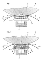
- Figure 1 shows a schematic representation of a between a Breitnip Anlagen 10 and a counter-roller 12 formed Breitnip 14 of a device 16 for influencing the gloss and / or smoothness of a material web, in particular, it is a paper or board web can act.
- the wide nip unit 10 comprises at least one in the web running direction L. extended broad nip shoe 18 and a guided over the wide-nip shoe 18 circulating flexible band 20.
- This can be wide nip unit 10 in particular by a Breitnipwalze with a on the broad nip shoe 18 or a associated with this, further under even closer to descriptive flexible or elastic plate guided flexible roll shell 20 be formed.
- the device 16 in question may in particular be a Breitnipkalander act.
- the Breitnipillon 10 moreover comprises at least one arranged between the Breitnipschuh 18 and the rotating flexible band 20 plate 22 made of flexible and / or elastic material and a plurality between this flexible or elastic plate 22 and the Breitnipschuh 18 provided, in the web running direction L successive actuators 24 i , over which the resulting in web direction L nip width B i is variably adjustable by a corresponding application of the flexible or ealstica plate 22.
- the actuators 24 i are preferably separately and / or group-controlled.
- the area between the flexible or elastic plate 22 and the circulating flexible band 20 is in particular hydrodynamically and / or hydrostatically lubricated.
- mechanical, hydraulic, pneumatic, electromechanical, electromagnetic and / or thermal actuators 24 i may be provided.
- the wide-nip shoe 18 can cross each other over several in the transverse direction following, on an axis supported Anpressticianen 26 acted upon be.
- These pressing units 26 are expediently separated and / or group-wise controllable, so that a respective under load occurring axis bending can be compensated.
- Figure 1 shows a schematic representation of an exemplary embodiment in which between the wide nip shoe 18 and the flexible or elastic plate 22 as actuators double-acting hydraulic cylinder / piston units 24 1 are provided.
- the broad nip shoe 18 is thus equipped on its side facing the counter roller 12 with actuators 24 1 , which act on a flexible or elastic plate 22 whose top is hydrodynamically or hydrostatically lubricated, so that the circumferential flexible band 20 optimally slide over the plate 22 can.
- actuators 24 1 By a corresponding activation of the actuators 24 1 , the nip width resulting in the web running direction L can be changed in the desired manner.
- the flexible or elastic plate 22 is provided on its side facing the broad nip shoe 18 with a plurality of sealing strips 28 which follow one another in the direction of web travel L and extend in each case in the transverse direction.
- the sealing strips 28 are guided in slots 30 provided in the wide-nip shoe 18.
- laterally limited pressure chambers 24 2 are formed between the wide-nip shoe 18 and the flexible or elastic plate 22 by the sealing strips 28, which can be acted upon correspondingly with pressure fluid for the variable adjustment of the nip width resulting in the web running direction L.
- the actuators in question thus include the pressure chambers 24 2 provided between the broad nip shoe 18 and the flexible or elastic plate 22 and bounded by the sealing strips 28.
- the pressure chambers 24 2 in the present case can be acted upon by pressurized fluid, in particular pressure oil, via feed channels 34 provided in the wide-nip shoe 18 and fed via a respective feed 32.
- pressurized fluid in particular pressure oil
- an elastomeric profile 36 is disposed between the wide nip shoe 18 and the flexible or elastic plate 22, which has a plurality of consecutive in the web running direction pressure chambers 24 2 , for the variable adjustment of the resulting in web direction L nip width B i accordingly with pressurized fluid, such as pressurized oil, can be acted upon.
- the relevant actuators thus include the pressure chambers 24 2 provided in the elastomer profile 36.
- a plurality of adjustment cams 24 4 following one another in the web running direction L are arranged between the wide-nip shoe 18 and the flexible or elastic plate.
- the variable adjustment of the nip width B i resulting in the web running direction L is variably adjustable are.
- the flexible or elastic plate 22 for setting a maximum nip width B 1 or a wide support of the circulating flexible band 20 on the mating roll 12 is acted upon accordingly by all setting cams 24 4 .
- two adjustment cams 24 4 ' are respectively correspondingly rotated both on the inlet side and on the outlet side end of the broad nip shoe 18 in order to set a reduced nip width B 2 .
- the flexible or elastic plate 20 is therefore pressed against the counter-roller 12 only by the remaining central adjusting cams 24 4 ", as already mentioned in connection with the embodiment according to FIG. 4 and also valid for the further embodiments, in the web running direction
- alternating pressurized and depressurized zones are created, and it is also possible, for example, to relieve the central part or desired subregions.
- a plurality of thermal actuators 24 5 following one another in the web running direction L are arranged between the wide-nip shoe 18 and the flexible or elastic plate 22.
- the nip width resulting in the web running direction L can be set variably via these thermal actuators 24 5 .
- the thermal actuators 24 5 each consist of thermally conductive material, wherein they are traversed by a heat medium.
- the nip width resulting in the web running direction L is thus variably adjustable by a corresponding variation of the temperature of the heat medium.
- the embodiment of Figure 8 corresponds in its basic structure of the embodiment of Figure 2, but instead of the pressure chambers provided there receiving chambers for individually controllable flexible tubes 37 are provided.
- the use of such pressurizable hoses leads to the advantage that no seals are required between moving parts. If in this case the flexible or elastic plate is formed without webs and the guided in corresponding recesses of Breitnipschuhs 18 or content Erten pressure hoses 37 directly to the plate 22, so there is a more mobile compared to the embodiment shown in Figure 8 and easier tilting arrangement.
- the embodiment of the broad nip shoe according to the invention can be the compressive stress in the nip in a simple way quickly and very sensitively to change.
- the invention is particularly advantageous for influencing gloss and / or smoothness of a paper or board web can be used, its scope is not limited to this.
- the invention can also be used in press sections for dewatering railways serve, are used in this case by targeted Actuation of the actuators corresponding application-specific advantages achieve.
Landscapes
- Paper (AREA)
Abstract
Description
Alternativ zu den durch die Dichtleisten begrenzten Druckkammern können vorteilhafterweise entsprechend ansteuerbare Schläuche in den von den Schlitzen und in diese eingreifenden Leisten gebildeten Kammern vorgesehen sein, wodurch jegliches Abdichten zwischen beweglichen Teilen entfällt. Wird die biegsame bzw. elastische Platte in diesem Falle ohne Stege ausgebildet und direkt über die Schläuche abgestützt, ergibt sich eine beweglichere und leichte kippbare Anordnung.
- Figur 1
- eine schematische Darstellung eines zwischen einer Breitnipeinheit und einer Gegenwalze gebildeten Breitnips einer Vorrichtung zur Beeinflussung von Glanz und/oder Glätte einer Materialbahn, wobei die zwischen dem Breitnipschuh und der biegsamen bzw. elastischen Platte vorgesehenen Aktuatoren durch doppelt wirkende Zylinder/Kolben-Einheiten gebildet sind,
- Figur 2
- eine schematische Darstellung einer Ausführungsform, bei der die biegsame bzw. elastische Platte über zwischen dieser und dem Breitnipschuh gebildete, durch Dichtleisten begrenzte Druckkammern beaufschlagbar ist,
- Figur 3
- eine schematische Darstellung einer Ausführungsform, bei der zwischen dem Breitnipschuh und der biegsamen bzw. elastischen Platte ein mehrere Druckkammern aufweisendes Elastomerprofil angeordnet ist, wobei im vorliegenden Fall alle Druckkammern unter Druck stehen,
- Figur 4
- eine mit der Figur 3 vergleichbare Darstellung, wobei jedoch sowohl am einlaufseitigen als auch auslaufseitigen Ende des Elastomerprofils jeweils zwei Druckkammern drucklos sind, d.h. nur die verbleibenden mittleren Druckkammern unter Druck stehen,
- Figur 5
- eine schematische Darstellung einer Ausführungsform, bei der zwischen dem Breitnipschuh und der biegsamen bzw. elastischen Platte mehrere Einstellnocken angeordnet sind, wobei im vorliegenden Fall die biegsame bzw. elastische Platte zur Einstellung einer maximalen Nipbreite durch alle Einstellnocken entsprechend beaufschlagt ist,
- Figur 6
- eine mit der Figur 5 vergleichbare Darstellung, wobei jedoch sowohl am einlaufseitigen als auch am auslaufseitigen Ende des Breitnipschuhs jeweils zwei Einstellnocken zur Einstellung einer verringerten Nipbreite entsprechend verdreht sind,
- Figur 7
- eine schematische Darstellung einer Ausführungsform, bei der zwischen dem Breitnipschuh und der biegsamen bzw. elastischen Platte mehrere thermische Aktuatoren angeordnet sind, und
- Figur 8
- eine schematische Darstellung einer Variante der Ausführungsform nach Figur 2, bei der anstelle von Druckkammern flexible Betätigungsschläuche vorgesehen sind.
Wird in diesem Falle die biegsame bzw. elastische Platte ohne Stege ausgebildet und werden die in entsprechenden Ausnehmungen des Breitnipschuhs 18 geführten bzw. gehalterten Druckschläuche 37 direkt an der Platte 22 abgestützt, so ergibt sich eine im Vergleich zu der in der Figur 8 dargestellten Ausgestaltung beweglichere und leichter kippbare Anordnung.
- 10
- Breitnipeinheit
- 12
- Gegenwalze
- 14
- Breitnip
- 16
- Vorrichtung
- 18
- Breitnipschuh
- 20
- flexibles Band, flexibler Walzenmantel
- 22
- biegsame bzw. elastische Platte
- 24i
- Aktuator
- 241
- Zylinder/ Kolben-Einheit
- 242
- Druckkammer
- 243
- Druckkammer
- 244
- Einstellnocken
- 245
- thermischer Aktuator
- 26
- Anpresseinheit
- 28
- Dichtleiste
- 30
- Schlitz
- 32
- Zulauf
- 34
- Zuführkanal
- 36
- Elastomerprofil
- 37
- Schlauch
- Bi
- Nipbreite
- L
- Bahnlaufrichtung
Claims (19)
- Vorrichtung (16) zur Behandlung einer Materialbahn, insbesondere zur Beeinflussung von Glanz und/oder Glätte einer Papier- oder Kartonbahn oder zur Entwässerung einer Papier- oder Faservliesbahn, mit wenigstens einem Breitnip (14), der zwischen einer Breitnipeinheit (10) mit wenigstens einem in Bahnlaufrichtung (L) verlängerten Breitnipschuh (18) sowie einem über den Breitnipschuh (18) geführten umlaufenden flexiblen Band (20) und einer komplementären Gegeneinheit (12) gebildet ist,
dadurch gekennzeichnet, dass die Breitnipeinheit (10) überdies wenigstens eine zwischen dem Breitnipschuh (18) und dem umlaufenden flexiblen Band (20) angeordnete, aus biegsamem und/oder elastischem Material bestehende Platte (22) sowie mehrere zwischen dieser und dem Breitnipschuh (18) vorgesehene, in Bahnlaufrichtung (L) aufeinander folgende Aktuatoren (24i) umfasst, über die die sich in Bahnlaufrichtung (L) ergebende Nipbreite (Bi) durch eine entsprechende Beaufschlagung der biegsamen bzw. elastischen Platte (22) variabel einstellbar ist. - Vorrichtung nach Anspruch 1,
dadurch gekennzeichnet, dass die Aktuatoren (24i) getrennt und/oder gruppenweise ansteuerbar sind. - Vorrichtung nach Anspruch 1 oder 2,
dadurch gekennzeichnet, dass der Bereich zwischen der biegsamen bzw. elastischen Platte (22) und dem umlaufenden flexiblen Band (20) hydrodynamisch und/oder hydrostatisch geschmiert ist. - Vorrichtung nach einem der vorhergehenden Ansprüche,
dadurch gekennzeichnet, dass mechanische, hydraulische, pneumatische, elektromechanische, elektromagnetische und/oder thermische Aktuatoren (24i) vorgesehen sind. - Vorrichtung nach einem der vorhergehenden Ansprüche,
dadurch gekennzeichnet, dass die Aktuatoren (24i) zumindest teilweise durch eine jeweilige Zylinder/Kolben-Einheit (241) gebildet sind. - Vorrichtung nach Anspruch 5,
dadurch gekennzeichnet, dass die Aktuatoren (24i) zumindest teilweise durch eine jeweilige hydraulische Zylinder/Kolben-Einheit (241) gebildet sind. - Vorrichtung nach Anspruch 5 oder 6,
dadurch gekennzeichnet, dass die Aktuatoren (24i) zumindest teilweise durch eine jeweilige doppelt wirkende Zylinder/Kolben-Einheit (241) gebildet sind. - Vorrichtung nach einem der Ansprüche 1 bis 4,
dadurch gekennzeichnet, dass die biegsame bzw. elastische Platte (22) auf ihrer dem Breitnipschuh (18) zugewandten Seite mit mehreren in Bahnlaufrichtung (L) aufeinander folgenden, sich jeweils in Querrichtung erstreckenden Dichtleisten (28) versehen ist, die in im Breitnipschuh (18) vorgesehene Schlitze (30) eintreten, um zwischen dem Breitnipschuh (18) und der biegsamen bzw. elastischen Platte durch die Dichtleisten begrenzte Druckkammern (242) zu bilden, die zur variablen Einstellung der sich in Bahnlaufrichtung (L) ergebenden Nipbreite (Bi) entsprechend mit Druckfluid beaufschlagbar sind. - Vorrichtung nach Anspruch 8,
dadurch gekennzeichnet, dass die Druckkammern (24i) über im Breitnipschuh (18) vorgesehene Zuführkanäle (34) mit Druckfluid beaufschlagbar sind. - Vorrichtung nach einem der Ansprüche 1 bis 4,
dadurch gekennzeichnet, dass die biegsame bzw. elastische Platte (22) auf ihrer dem Breitnipschuh (18) zugewandten Seite mit mehreren in Bahnlaufrichtung (L) aufeinander folgenden, sich jeweils in Querrichtung erstreckenden Leisten (28) versehen ist, die in im Breitnipschuh (18) vorgesehene Schlitze eintreten, in denen zur variablen Einstellung der sich in Bahnlaufrichtung (L) ergebenden Nipbreite (Bi) und/oder zur Vorgabe eines frei wählbaren Belastungsprofils in Bahnlaufrichtung (L) jeweils ein individuell ansteuerbarer Druckschlauch (37) vorgesehen ist. - Vorrichtung nach Anspruch 10,
dadurch gekennzeichnet, dass die Druckschläuche (37) in Führungs- und Halteausnehmungen des Breitnipschuhs (18) angeordnet sind und die biegsame bzw. elastische Platte (22) direkt auf den Schläuchen (37) abgestützt ist. - Vorrichtung nach einem der Ansprüche 1 bis 4,
dadurch gekennzeichnet, dass zwischen dem Breitnipschuh (18) und der biegsamen bzw. elastischen Platte (22) ein Elastomerprofil (36) angeordnet ist, das mehrere in Bahnlaufrichtung (L) aufeinander folgende Druckkammern (243) aufweist, die zur variablen Einstellung der sich in Bahnlaufrichtung (L) ergebenden Nipbreite (Bi) entsprechend mit Druckfluid beaufschlagbar sind. - Vorrichtung nach einem der Ansprüche 1 bis 4,
dadurch gekennzeichnet, dass zwischen dem Breitnipschuh (18) und der biegsamen bzw. elastischen Platte (22) mehrere in Bahnlaufrichtung (L) aufeinander folgende Einstellnocken (244) angeordnet sind und dass die sich in Bahnlaufrichtung (L) ergebende Nipbreite (Bi) über diese Einstellnocken (244) variabel einstellbar ist. - Vorrichtung nach einem der Ansprüche 1 bis 4,
dadurch gekennzeichnet, dass zwischen dem Breitnipschuh (18) und der biegsamen bzw. elastischen Platte (22) mehrere in Bahnlaufrichtung (L) aufeinander folgende thermische Aktuatoren (245) angeordnet sind und dass die sich in Bahnlaufrichtung (L) ergebende Nipbreite (Bi) über diese thermischen Aktuatoren (245) variabel einstellbar ist. - Vorrichtung nach Ansprüche 14,
dadurch gekennzeichnet, dass die thermischen Aktuatoren (245) jeweils aus wärmeleitfähigem Material bestehen und von einem Wärmemedium durchströmt sind und dass die sich in Bahnlaufrichtung (L) ergebende Nipbreite (Bi) durch eine entsprechende Variation der Temperatur des Wärmemediums variabel einstellbar ist. - Vorrichtung nach einem der vorhergehenden Ansprüche,
dadurch gekennzeichnet, dass der Breitnipschuh (18) über mehrere in Querrichtung aufeinander folgende, an einer Achse abgestützte Anpresseinheiten (26) beaufschlagbar ist. - Vorrichtung nach Anspruch 16,
dadurch gekennzeichnet, dass die Anpresseinheiten (26) getrennt und/oder gruppenweise ansteuerbar sind. - Vorrichtung nach einem der vorhergehenden Ansprüche,
dadurch gekennzeichnet, dass die Breitnipeinheit (10) durch eine Breitnipwalze mit einem über die biegsame bzw. elastische Platte (22) geführten flexiblen Walzenmantel (20) gebildet ist. - Vorrichtung nach einem der vorhergehenden Ansprüche,
dadurch gekennzeichnet, dass sie zumindest einen Breitnipkalander umfasst.
Applications Claiming Priority (2)
| Application Number | Priority Date | Filing Date | Title |
|---|---|---|---|
| DE2003136230 DE10336230A1 (de) | 2003-08-07 | 2003-08-07 | Vorrichtung zur Behandlung einer Materialbahn |
| DE10336230 | 2003-08-07 |
Publications (2)
| Publication Number | Publication Date |
|---|---|
| EP1505202A1 true EP1505202A1 (de) | 2005-02-09 |
| EP1505202B1 EP1505202B1 (de) | 2009-01-28 |
Family
ID=33547131
Family Applications (2)
| Application Number | Title | Priority Date | Filing Date |
|---|---|---|---|
| EP04102679A Withdrawn EP1505204A1 (de) | 2003-08-07 | 2004-06-14 | Vorrichtung zur Behandlung einer Materialbahn |
| EP20040018282 Expired - Lifetime EP1505202B1 (de) | 2003-08-07 | 2004-08-02 | Vorrichtung zur Behandlung einer Materialbahn |
Family Applications Before (1)
| Application Number | Title | Priority Date | Filing Date |
|---|---|---|---|
| EP04102679A Withdrawn EP1505204A1 (de) | 2003-08-07 | 2004-06-14 | Vorrichtung zur Behandlung einer Materialbahn |
Country Status (2)
| Country | Link |
|---|---|
| EP (2) | EP1505204A1 (de) |
| DE (2) | DE10336230A1 (de) |
Families Citing this family (3)
| Publication number | Priority date | Publication date | Assignee | Title |
|---|---|---|---|---|
| DE102007060400B3 (de) * | 2007-12-14 | 2009-05-28 | Andritz Küsters Gmbh | Vorrichtung zum Bilden eines Langspalts |
| DE102010030327A1 (de) * | 2010-06-22 | 2011-12-22 | Voith Patent Gmbh | Bahnbehandlungsvorrichtung zum Glätten einer Faserstoffbahn |
| EP2808442B1 (de) * | 2013-05-29 | 2015-11-18 | Andritz Küsters GmbH | Vorrichtung zum Bilden eines Langspalts |
Citations (5)
| Publication number | Priority date | Publication date | Assignee | Title |
|---|---|---|---|---|
| DE1704767A1 (de) * | 1967-09-15 | 1971-02-25 | Ashihara Tekkosho Kk | Einrichtung zum kontinuierlichen Pressen von bandartigen Gegenstaenden unter Erwaermung oder Kuehlung |
| US4576682A (en) * | 1983-03-23 | 1986-03-18 | Valmet Oy | Long-nip press for a paper making machine |
| DE4103343A1 (de) * | 1991-02-05 | 1992-08-06 | Berstorff Gmbh Masch Hermann | Vorrichtung zum kontinuierlichen pressen eines endlosen materialbandes |
| DE19607144A1 (de) * | 1996-02-26 | 1997-08-28 | Voith Sulzer Papiermasch Gmbh | Preßvorrichtung |
| US6334933B1 (en) * | 1999-04-14 | 2002-01-01 | Metso Chemical Pulping Oy | Press |
Family Cites Families (3)
| Publication number | Priority date | Publication date | Assignee | Title |
|---|---|---|---|---|
| DD218918A1 (de) * | 1982-12-14 | 1985-02-20 | Freiberg Papier Maschwerke | Vorrichtung zum anpressen eines umlaufenden bandes |
| DE4425915A1 (de) * | 1994-07-21 | 1996-02-01 | Voith Sulzer Papiermasch Gmbh | Langspalt-Presse |
| DE19544979B4 (de) * | 1995-12-01 | 2006-08-03 | Voith Paper Patent Gmbh | Vorrichtung zum Komprimieren, Glätten und/oder Entwässern einer Faserstoffbahn |
-
2003
- 2003-08-07 DE DE2003136230 patent/DE10336230A1/de not_active Withdrawn
-
2004
- 2004-06-14 EP EP04102679A patent/EP1505204A1/de not_active Withdrawn
- 2004-08-02 EP EP20040018282 patent/EP1505202B1/de not_active Expired - Lifetime
- 2004-08-02 DE DE200450008938 patent/DE502004008938D1/de not_active Expired - Lifetime
Patent Citations (5)
| Publication number | Priority date | Publication date | Assignee | Title |
|---|---|---|---|---|
| DE1704767A1 (de) * | 1967-09-15 | 1971-02-25 | Ashihara Tekkosho Kk | Einrichtung zum kontinuierlichen Pressen von bandartigen Gegenstaenden unter Erwaermung oder Kuehlung |
| US4576682A (en) * | 1983-03-23 | 1986-03-18 | Valmet Oy | Long-nip press for a paper making machine |
| DE4103343A1 (de) * | 1991-02-05 | 1992-08-06 | Berstorff Gmbh Masch Hermann | Vorrichtung zum kontinuierlichen pressen eines endlosen materialbandes |
| DE19607144A1 (de) * | 1996-02-26 | 1997-08-28 | Voith Sulzer Papiermasch Gmbh | Preßvorrichtung |
| US6334933B1 (en) * | 1999-04-14 | 2002-01-01 | Metso Chemical Pulping Oy | Press |
Also Published As
| Publication number | Publication date |
|---|---|
| DE10336230A1 (de) | 2005-03-03 |
| EP1505204A1 (de) | 2005-02-09 |
| EP1505202B1 (de) | 2009-01-28 |
| DE502004008938D1 (de) | 2009-03-19 |
Similar Documents
| Publication | Publication Date | Title |
|---|---|---|
| DE3102526C2 (de) | Preßeinrichtung zum Entwässern von Bahnen, insbesondere Papierbahnen | |
| DE3022491C2 (de) | Druckbehandlungswalze | |
| EP0155465B1 (de) | Nasspresse zum Entwässern einer Warenbahn | |
| CH657396A5 (de) | Walzenaggregat fuer papier- und andere materialbahnen. | |
| DE3503819A1 (de) | Hydraulischer pressschuh sowie dessen verwendung und betrieb | |
| EP0675224A1 (de) | Pressvorrichtung für bahnförmiges Material | |
| EP1279766B1 (de) | Durchbiegungseinstellwalze | |
| EP1081276A2 (de) | Trocknungsvorrichtung | |
| EP0732445B2 (de) | Kalander für die Behandlung einer Papierbahn | |
| DE60011219T2 (de) | Presse zur entwässerung einer faserbahn | |
| EP0870865A2 (de) | Schuhpresseinheit | |
| DE3637108A1 (de) | Pressenwalze, die insbesondere zur behandlung einer papierbahn oder dergleichen dient | |
| EP1505204A1 (de) | Vorrichtung zur Behandlung einer Materialbahn | |
| EP2808442B1 (de) | Vorrichtung zum Bilden eines Langspalts | |
| DE60033137T2 (de) | Weichkrepp-papiermaschine und deren Pressenpartie | |
| CH670217A5 (de) | ||
| EP1995378A2 (de) | Schuhsaugpresswalze | |
| DE112010003542T5 (de) | Walze mit einstellbarem Mantel, Vorrichtung und Verfahren | |
| EP1285990B1 (de) | Vorrichtung zum Bilden eines Langspalts | |
| DE10207371B4 (de) | Vorrichtung zum Bilden eines Langspalts | |
| EP1505201A2 (de) | Vorrichtung zur Behandlung einer Materialbahn | |
| DE60029892T2 (de) | Pressenvorrichtung mit einer Membrane | |
| DE102007055734A1 (de) | Bahnbehandlungsvorrichtung | |
| DE60009119T2 (de) | Verfahren zur querrichtungsprofilierung einer papier- oder pappebahn in einem spalt | |
| DE10157691A1 (de) | Kalander und Verfahren zum Glätten einer Faserstoffbahn |
Legal Events
| Date | Code | Title | Description |
|---|---|---|---|
| PUAI | Public reference made under article 153(3) epc to a published international application that has entered the european phase |
Free format text: ORIGINAL CODE: 0009012 |
|
| AK | Designated contracting states |
Kind code of ref document: A1 Designated state(s): AT BE BG CH CY CZ DE DK EE ES FI FR GB GR HU IE IT LI LU MC NL PL PT RO SE SI SK TR |
|
| AX | Request for extension of the european patent |
Extension state: AL HR LT LV MK |
|
| 17P | Request for examination filed |
Effective date: 20050322 |
|
| AKX | Designation fees paid |
Designated state(s): DE FI SE |
|
| RAP1 | Party data changed (applicant data changed or rights of an application transferred) |
Owner name: VOITH PATENT GMBH |
|
| 17Q | First examination report despatched |
Effective date: 20070621 |
|
| GRAP | Despatch of communication of intention to grant a patent |
Free format text: ORIGINAL CODE: EPIDOSNIGR1 |
|
| GRAS | Grant fee paid |
Free format text: ORIGINAL CODE: EPIDOSNIGR3 |
|
| GRAA | (expected) grant |
Free format text: ORIGINAL CODE: 0009210 |
|
| AK | Designated contracting states |
Kind code of ref document: B1 Designated state(s): DE FI SE |
|
| REF | Corresponds to: |
Ref document number: 502004008938 Country of ref document: DE Date of ref document: 20090319 Kind code of ref document: P |
|
| REG | Reference to a national code |
Ref country code: SE Ref legal event code: TRGR |
|
| PLBI | Opposition filed |
Free format text: ORIGINAL CODE: 0009260 |
|
| PLAX | Notice of opposition and request to file observation + time limit sent |
Free format text: ORIGINAL CODE: EPIDOSNOBS2 |
|
| 26 | Opposition filed |
Opponent name: METSO PAPER KARLSTAD AKTIEBOLAG Effective date: 20091027 |
|
| PLBB | Reply of patent proprietor to notice(s) of opposition received |
Free format text: ORIGINAL CODE: EPIDOSNOBS3 |
|
| PGFP | Annual fee paid to national office [announced via postgrant information from national office to epo] |
Ref country code: SE Payment date: 20110824 Year of fee payment: 8 Ref country code: DE Payment date: 20110823 Year of fee payment: 8 Ref country code: FI Payment date: 20110812 Year of fee payment: 8 |
|
| PLCK | Communication despatched that opposition was rejected |
Free format text: ORIGINAL CODE: EPIDOSNREJ1 |
|
| REG | Reference to a national code |
Ref country code: SE Ref legal event code: EUG |
|
| PG25 | Lapsed in a contracting state [announced via postgrant information from national office to epo] |
Ref country code: FI Free format text: LAPSE BECAUSE OF NON-PAYMENT OF DUE FEES Effective date: 20120802 Ref country code: SE Free format text: LAPSE BECAUSE OF NON-PAYMENT OF DUE FEES Effective date: 20120803 |
|
| PLBN | Opposition rejected |
Free format text: ORIGINAL CODE: 0009273 |
|
| STAA | Information on the status of an ep patent application or granted ep patent |
Free format text: STATUS: OPPOSITION REJECTED |
|
| 27O | Opposition rejected |
Effective date: 20130203 |
|
| PG25 | Lapsed in a contracting state [announced via postgrant information from national office to epo] |
Ref country code: DE Free format text: LAPSE BECAUSE OF NON-PAYMENT OF DUE FEES Effective date: 20130301 |
|
| REG | Reference to a national code |
Ref country code: DE Ref legal event code: R119 Ref document number: 502004008938 Country of ref document: DE Effective date: 20130301 |