EP1505001B1 - Verfahren zur Herstellung eines kastenförmigen Ladungsträgers aus thermoplastischem Kunststoff - Google Patents
Verfahren zur Herstellung eines kastenförmigen Ladungsträgers aus thermoplastischem Kunststoff Download PDFInfo
- Publication number
- EP1505001B1 EP1505001B1 EP04018451A EP04018451A EP1505001B1 EP 1505001 B1 EP1505001 B1 EP 1505001B1 EP 04018451 A EP04018451 A EP 04018451A EP 04018451 A EP04018451 A EP 04018451A EP 1505001 B1 EP1505001 B1 EP 1505001B1
- Authority
- EP
- European Patent Office
- Prior art keywords
- produced
- side walls
- edges
- notching
- plasticization
- Prior art date
- Legal status (The legal status is an assumption and is not a legal conclusion. Google has not performed a legal analysis and makes no representation as to the accuracy of the status listed.)
- Expired - Lifetime
Links
- 239000012815 thermoplastic material Substances 0.000 title claims abstract description 9
- 238000000034 method Methods 0.000 title claims description 7
- 238000004519 manufacturing process Methods 0.000 title abstract description 11
- 238000010438 heat treatment Methods 0.000 claims description 12
- 239000000463 material Substances 0.000 claims description 4
- 239000002800 charge carrier Substances 0.000 description 17
- 238000009960 carding Methods 0.000 description 15
- 239000004033 plastic Substances 0.000 description 9
- 229920003023 plastic Polymers 0.000 description 9
- 238000003860 storage Methods 0.000 description 5
- 238000003754 machining Methods 0.000 description 4
- 238000005520 cutting process Methods 0.000 description 3
- 238000003466 welding Methods 0.000 description 3
- 239000011324 bead Substances 0.000 description 2
- 238000005452 bending Methods 0.000 description 2
- 239000000969 carrier Substances 0.000 description 2
- 238000005516 engineering process Methods 0.000 description 2
- 238000002844 melting Methods 0.000 description 2
- 230000008018 melting Effects 0.000 description 2
- 239000002184 metal Substances 0.000 description 2
- 239000000853 adhesive Substances 0.000 description 1
- 238000004026 adhesive bonding Methods 0.000 description 1
- 230000001070 adhesive effect Effects 0.000 description 1
- 238000004140 cleaning Methods 0.000 description 1
- 238000010276 construction Methods 0.000 description 1
- 238000009749 continuous casting Methods 0.000 description 1
- 238000005260 corrosion Methods 0.000 description 1
- 230000007797 corrosion Effects 0.000 description 1
- 230000001419 dependent effect Effects 0.000 description 1
- 238000001746 injection moulding Methods 0.000 description 1
- JEIPFZHSYJVQDO-UHFFFAOYSA-N iron(III) oxide Inorganic materials O=[Fe]O[Fe]=O JEIPFZHSYJVQDO-UHFFFAOYSA-N 0.000 description 1
- 238000005304 joining Methods 0.000 description 1
- 230000000414 obstructive effect Effects 0.000 description 1
- 230000035515 penetration Effects 0.000 description 1
- 238000002360 preparation method Methods 0.000 description 1
- 238000004080 punching Methods 0.000 description 1
- 230000006641 stabilisation Effects 0.000 description 1
- 238000011105 stabilization Methods 0.000 description 1
- XLYOFNOQVPJJNP-UHFFFAOYSA-N water Substances O XLYOFNOQVPJJNP-UHFFFAOYSA-N 0.000 description 1
- 239000002023 wood Substances 0.000 description 1
Images


Classifications
-
- B—PERFORMING OPERATIONS; TRANSPORTING
- B29—WORKING OF PLASTICS; WORKING OF SUBSTANCES IN A PLASTIC STATE IN GENERAL
- B29C—SHAPING OR JOINING OF PLASTICS; SHAPING OF MATERIAL IN A PLASTIC STATE, NOT OTHERWISE PROVIDED FOR; AFTER-TREATMENT OF THE SHAPED PRODUCTS, e.g. REPAIRING
- B29C53/00—Shaping by bending, folding, twisting, straightening or flattening; Apparatus therefor
- B29C53/02—Bending or folding
- B29C53/04—Bending or folding of plates or sheets
- B29C53/06—Forming folding lines by pressing or scoring
- B29C53/063—Forming folding lines by pressing or scoring combined with folding
- B29C53/066—Forming folding lines by pressing or scoring combined with folding and joining the sides of the folding line, e.g. "Abkantschweissen"
-
- B—PERFORMING OPERATIONS; TRANSPORTING
- B65—CONVEYING; PACKING; STORING; HANDLING THIN OR FILAMENTARY MATERIAL
- B65D—CONTAINERS FOR STORAGE OR TRANSPORT OF ARTICLES OR MATERIALS, e.g. BAGS, BARRELS, BOTTLES, BOXES, CANS, CARTONS, CRATES, DRUMS, JARS, TANKS, HOPPERS, FORWARDING CONTAINERS; ACCESSORIES, CLOSURES, OR FITTINGS THEREFOR; PACKAGING ELEMENTS; PACKAGES
- B65D1/00—Rigid or semi-rigid containers having bodies formed in one piece, e.g. by casting metallic material, by moulding plastics, by blowing vitreous material, by throwing ceramic material, by moulding pulped fibrous material or by deep-drawing operations performed on sheet material
- B65D1/22—Boxes or like containers with side walls of substantial depth for enclosing contents
-
- B—PERFORMING OPERATIONS; TRANSPORTING
- B65—CONVEYING; PACKING; STORING; HANDLING THIN OR FILAMENTARY MATERIAL
- B65D—CONTAINERS FOR STORAGE OR TRANSPORT OF ARTICLES OR MATERIALS, e.g. BAGS, BARRELS, BOTTLES, BOXES, CANS, CARTONS, CRATES, DRUMS, JARS, TANKS, HOPPERS, FORWARDING CONTAINERS; ACCESSORIES, CLOSURES, OR FITTINGS THEREFOR; PACKAGING ELEMENTS; PACKAGES
- B65D21/00—Nestable, stackable or joinable containers; Containers of variable capacity
- B65D21/02—Containers specially shaped, or provided with fittings or attachments, to facilitate nesting, stacking, or joining together
- B65D21/0209—Containers specially shaped, or provided with fittings or attachments, to facilitate nesting, stacking, or joining together stackable or joined together one-upon-the-other in the upright or upside-down position
- B65D21/0224—Auxiliary removable stacking elements other than covers
-
- B—PERFORMING OPERATIONS; TRANSPORTING
- B65—CONVEYING; PACKING; STORING; HANDLING THIN OR FILAMENTARY MATERIAL
- B65D—CONTAINERS FOR STORAGE OR TRANSPORT OF ARTICLES OR MATERIALS, e.g. BAGS, BARRELS, BOTTLES, BOXES, CANS, CARTONS, CRATES, DRUMS, JARS, TANKS, HOPPERS, FORWARDING CONTAINERS; ACCESSORIES, CLOSURES, OR FITTINGS THEREFOR; PACKAGING ELEMENTS; PACKAGES
- B65D5/00—Rigid or semi-rigid containers of polygonal cross-section, e.g. boxes, cartons or trays, formed by folding or erecting one or more blanks made of paper
- B65D5/001—Rigid or semi-rigid containers of polygonal cross-section, e.g. boxes, cartons or trays, formed by folding or erecting one or more blanks made of paper stackable
- B65D5/005—Separate or attached stacking elements
- B65D5/0055—Separate or attached stacking elements saddling the side walls of the container
-
- B—PERFORMING OPERATIONS; TRANSPORTING
- B29—WORKING OF PLASTICS; WORKING OF SUBSTANCES IN A PLASTIC STATE IN GENERAL
- B29L—INDEXING SCHEME ASSOCIATED WITH SUBCLASS B29C, RELATING TO PARTICULAR ARTICLES
- B29L2031/00—Other particular articles
- B29L2031/712—Containers; Packaging elements or accessories, Packages
Definitions
- the invention relates to a method for producing a stackable charge carrier made of thermoplastic material for storage or for one-way and multi-way transport of packaged goods of all kinds, in particular of small parts.
- Load carriers are used as transport and storage containers, especially where tools or components have to be transported or stored in the course of a manufacturing process. They usually consist of metal sheets, wood or plastic plates, which can be glued, welded or positively connected with each other. It is also important in addition to a sufficient load capacity and life, that the container as possible have no projections or heels that constrict the interior or otherwise obstructive. Partially, additional inserts are provided in the interior, although lining the interior completely and without projections, however, themselves do not have sufficient capacity and mean additional effort.
- Injection-molded charge carriers as well as charge carriers made of PP hollow-chamber material of different types are known for comparable usage tasks.
- the injection molding boxes are containers produced in elaborate shapes. Due to the high tooling costs, these are only produced in large quantities.
- Comparable PP hollow boxes are characterized either by the fact that they are assembled from many individual parts, which require a large number of individual steps or by simple folding and bending constructions, which are held in shape by means of a circumferential stacking profile. This involves thermal bending, ultrasonic welding, adhesive technology and other joining and machining operations. Regularly resulting in edges that are not closed. There, in wet cleaning and outdoor storage of the container penetrate water and lead in the transport and storage process to unwanted moisture or rust on the parts to be transported.
- the containers are characterized by the fact that thanks to their low tooling costs even the smallest quantities of different dimensions can be produced.
- a charge carrier in which the side walls are hollow-chamber plates made of thermoplastic material.
- the upper edges of the side walls are provided with a carding edge, which is integrally formed on the side walls and formed by a rigid fold of the hollow chamber plate. This forms a circumferential cavity.
- the lower end of the carding edge is separated from the side walls by an open joint.
- On the sides and corners of the side walls are held together by means of connectors by edge, fold and side connector form-fitting.
- the described carrier has a complicated structure with many projections and edges and heels. Its production is very complicated by the many items.
- US-A-6 056 840 discloses a method for producing a box-shaped charge carrier made of thermoplastic material with a bottom and 4 side walls.
- a simultaneous melting takes place along the lines to be welded.
- the side panels are folded together and merge permanently.
- Short-term one-offs or small batches are ineffective to produce, since for each load carrier size a separate arrangement has to be made of heating swords.
- the object of the invention is the development of a method for the simple and cost-effective production of a plastic load carrier.
- the charge carrier is always made of thermoplastic material. It has a bottom and 4 side walls, which are made of a flat output plate.
- This output plate is preferably a hollow chamber plate. Hollow panels have a smooth surface and a low weight with high rigidity due to their intermediate honeycomb structure. As a result, larger charge carriers can be produced with a high load capacity.
- the output plate may also consist of thermoplastic material.
- a line-shaped notch is inserted, around which the side walls are foldable into a box-shaped base body.
- the abutting vertical edges of the side walls are miter welded.
- At the upper edges of the side walls optionally includes a carding edge, which is folded around a line-shaped notch in the output plate by 180 ° to the respective side wall.
- a stacking profile is positively clipped in such a way that a projection formed on the stacking profile fixes the stacking profile on the carding edge.
- the stack profile is preferably completely encircling around the upper edge of the charge carrier.
- a stacking corner is placed, which has a carding edge similar shaped connector.
- the stack profile is positively clipped between the stacking corners above the carding edge and above the connecting piece such that a projection formed on the stacking profile fixes the stacking profile on the carding edge and the connecting piece.
- the stacking corner and the stacking profile have the same circumferential shape.
- corner angles are attached to the vertical edges of the side walls, which are glued or welded over the entire surface. To accommodate the stacking forces, the corner angles extend as far as possible below the corner angle or below the stacking profile.
- At least one handle is attached to the side walls.
- two handles are arranged on the opposite side walls.
- the handles themselves are glued on the side walls over the entire surface, welded or inserted or clipped into recesses of the side walls.
- the handles extend as far as possible to the lower edge of the carding edge or stacking profile.
- the stacking profiles and / or the stacking corners and / or the handles are preferably injection-molded or extruded parts.
- the box-shaped charge carrier made of thermoplastic material is produced from a flat output plate.
- a mold is first prepared which corresponds to the basic body to be manufactured. For a rectangular base this would be the shape of a "Swiss cross".
- a notch is produced by means of two V-shaped heating blades, which are fastened to parallel movable axes, by plasticizing the plastic.
- a miter-like slope is produced along the edges to be welded by means of the heating blades by plasticizing the plastic.
- the output plate is extended by a carding edge.
- the flat output plate along a Umklappline for the carding edge by means of the Schuter a notch is formed, which allows a hinge-like folding the carding edge to the side panels.
- a rectangular, 5 mm thick plastic hollow-chamber plate is brought into a shape which corresponds approximately to a "Swiss cross". This can be done by cutting or punching. The absolutely parallel course of all edges is of crucial importance.
- corner angle 2 The thereby separated corners are used and processed according to corner angle 2.
- the lateral edges of the corner angle 2 are closed by the penetration of the V-shaped heating blades in the form of a slope.
- the parts are canted parallel to their long side in the middle, by means of the heating swords at 90 ° angle.
- the short sides are bluntly welded over the entire surface and brought to length.
- the cut-to-size "Swiss Cross" is machined on a machine with two V-shaped heated swords attached to parallel axes.
- the blank is placed on a 90 ° rotating base plate.
- a notch 9 is formed on all sides in parallel at a distance of about 30 mm.
- the swords penetrate from above into the plate, weld the separate end faces in a V-shape and leave a thin hinged band on the underside of the plate. It will always be used simultaneously both Bank.
- the blank to be machined rotates on the rotatable base plate by exactly 90 °. It takes place the second processing step for generating the notch 9 located at right angles.
- the two heating blades move exactly so far that the center of the sword vertex lines are placed vertically above the edges of the "Swiss Cross" to be machined. Similar to hinge machining, the swords dip into the workpiece from above, creating a miter-like slope and surface. Still in the hot, plasticized state, the workpiece is rotated and the corresponding edges are processed analogously at right angles. These edges are also deformed to Gehrungschrägen. Even in the plasticized state of the four miter lines, the four adjoining sides are folded upwards at right angles to the base rectangle. The miter slopes touch in the plasticized state and fuse together. The result is an all-welded base box.
- the cling edges 5 attached to the hinge straps are folded 180 ° outwards and downwards. The result is a non-circumferential bead on the upper edges of the container.
- Prefabricated stacking corners 4 with an integrally formed connecting piece 7 are plugged onto the corners as injection-molded elements. The remaining distances between the stacking corners 4 are thereby supplemented without bead so that correspondingly cut to length stacking profiles 3 are used on the connecting pieces 7 of the stacking corners 4 and on the carding edge 5.
- An integrally formed on the stack profile 3 projection 11 allows a clipping on the carding edge.
- the stack profiles 3 fix the four stacking corners 4 of the charge carrier, without further connection technology, such as welding or gluing.
- the stack profiles 3 are continuous castings in the example described.
- the processed corner brackets 2 are plasticized on their insides by heat and pressed onto the equally heated outer corner surfaces of the charge carrier. It comes here for full-surface welding of the patch corner 2 with the hollow panel base body. In this case, an enormous torsional rigidity and stack load capacity is generated.
Landscapes
- Engineering & Computer Science (AREA)
- Mechanical Engineering (AREA)
- Ceramic Engineering (AREA)
- Rigid Containers With Two Or More Constituent Elements (AREA)
- Shaping Of Tube Ends By Bending Or Straightening (AREA)
- Cartons (AREA)
- Macromolecular Compounds Obtained By Forming Nitrogen-Containing Linkages In General (AREA)
- Packaging Of Annular Or Rod-Shaped Articles, Wearing Apparel, Cassettes, Or The Like (AREA)
- Purses, Travelling Bags, Baskets, Or Suitcases (AREA)
Description
- Die Erfindung betrifft ein Verfahren zur Herstellung eines stapelbaren Ladungsträgers aus thermoplastischem Kunststoff zur Aufbewahrung bzw. zum Ein- und Mehrwegetransport von Verpackungsgut aller Art, insbesondere von Kleinteilen.
- Ladungsträger werden als Transport- und Lagerbehälter insbesondere dort eingesetzt, wo Werkzeuge oder Bauteile im Rahmen eines Herstellungsprozesses transportiert oder zwischengelagert werden müssen. Sie bestehen üblicherweise aus Metallblechen, Holz- oder Kunststoffplatten, die verklebt, verschweißt oder formschlüssig miteinander verbunden sein können. Dabei ist neben einer ausreichenden Tragkraft und Lebensdauer auch wichtig, dass die Behälter möglichst keine Vorsprünge oder Absätze aufweisen, die den Innenraum einengen oder anderweitig hinderlich sind. Teilweise sind im Innenraum auch zusätzliche Einsätze vorgesehen, die zwar den Innenraum vollständig und ohne Vorsprünge auskleiden, die jedoch selbst keine ausreichende Tragfähigkeit besitzen und zusätzlichen Aufwand bedeuten.
- Ladungsträger aus Metall sind zwar relativ stabil, aber oft sehr schwer, korrosionsanfällig und lärmbelästigend beim Umgang. Die Verwendung von Kunststoffen hat den Vorteil, dass die Behälter ein relativ geringes Gewicht aufweisen. Andererseits hat die Verwendung von Kunststoffen den Nachteil, dass die Behälter oft nur eine geringe Stabilität besitzen.
- Für vergleichbare Nutzungsaufgaben sind Spritzguss-Ladungsträger sowie aus PP-Hohlkammermaterial hergestellte Ladungsträger unterschiedlicher Bauart bekannt.
- Bei den Spritzgusskisten handelt es sich um in aufwendigen Formen hergestellte Behälter. Diese werden auf Grund der hohen Werkzeugkosten nur in großen Stückzahlen hergestellt. Vergleichbare PP-Hohlkammerkisten zeichnen sich entweder dadurch aus, dass Sie aus vielen Einzelteilen zusammengefügt werden, die eine Vielzahl von Einzelarbeitsschritten erforderlich machen oder durch einfache Falt- und Biegekonstruktionen, die mittels eines umlaufenden Stapelprofils in Form gehalten werden. Dabei kommen thermische Abkantungen, Ultraschweißtechnik, Klebetechnik und andere Füge- und Bearbeitungsgänge zum tragen. Regelmäßig ergeben sich dabei Kanten, die nicht verschlossen sind. Dort kann bei Nassreinigung und Außenlagerung der Behälter Wasser eindringen und im Transport- und Lagerprozess zu ungewollter Feuchtigkeit bzw. Rostbildung an den zu transportierenden Teilen führen. Grundsätzlich zeichnen sich die Behälter dadurch aus, dass dank geringer Werkzeugkosten auch kleinste Stückzahlen unterschiedlichster Abmessungen hergestellt werden können.
- Aus
DE 295 17 978 U1 ist ein Ladungsträger bekannt, bei dem die Seitenwände Hohlkammerplatten aus thermoplastischem Kunststoff sind. Die oberen Kanten der Seitenwände sind mit einem Krempelrand versehen, der einstückig an die Seitenwände angeformt und durch eine starre Abkantung der Hohlkammerplatte gebildet wird. Dabei bildet sich ein umlaufender Hohlraum aus. Das untere Ende des Krempelrandes ist durch eine offene Fuge von den Seitenwänden getrennt. An den Seiten und Ecken werden die Seitenwände mittels Verbindungsstücken durch Kanten-, Falz- und Seitenverbinder formschlüssig zusammengehalten. Der beschriebene Ladungsträger hat einen komplizierten Aufbau mit vielen Vorsprüngen und Kanten und Absätzen. Seine Herstellung ist durch die vielen Einzelteile sehr aufwendig. -
US-A-6 056 840 offenbart ein Verfahren zur Herstellung eines kastenförmigen Ladungsträgers aus thermoplastischem Kunststoff mit einem Boden und 4 Seitenwänden. Mittels mehrerer Heizschwerter erfolgt ein gleichzeitiges Anschmelzen entlang der zu verschweißenden Linien. Noch im plastischen Zustand werden die Seitenteile aneinandergeklappt und verschmelzen dauerhaft. Kurzfristige Einzelanfertigungen oder Kleinserien sind jedoch uneffektiv herzustellen, da für jede Ladungsträgergröße eine gesonderte Anordnung an Heizschwertern angefertigt werden muss. - In
US-A-4 090 903 werden kastenförmige Ladungsträger mittels Schneidschwertern hergestellt, die auf einer Heizplatte fest aufgebracht sind und von dieser die Wärme zum Anschmelzen der Schneidlinien erhalten. - In
EP-A-0 436 236 wird die Herstellung von kastenförmigen Ladungsträgern mit feststehenden Heizelementen beschrieben. - Aufgabe der Erfindung ist die Entwicklung eines Verfahrens zur einfachen und kostengünstigen Herstellung eines Kunststoffladungsträgers.
- Diese Aufgabe wird erfindungsgemäß durch die Verfahrensmerkmale des Anspruches 1 gelöst. Ausgestaltende Merkmale sind im Unteranspruch 2 beschrieben.
- Der Aufbau und die Herstellung des erfindungsgemäßen Ladungsträgers sind wie folgt:
- Der Ladungsträger wird stets aus thermoplastischem Kunststoff hergestellt. Er besitzt einen Boden und 4 Seitenwände, die aus einer flächigen Ausgangsplatte hergestellt sind. Diese Ausgangsplatte ist vorzugsweise eine Hohlkammerplatte. Hohlkammerplatten haben eine glatte Oberfläche und durch ihre zwischenliegende Wabenstruktur ein geringes Gewicht bei einer hohen Steifigkeit. Dadurch können auch größere Ladungsträger mit einer hohen Traglast hergestellt werden. Für geringere Anforderungen kann die Ausgangsplatte auch aus thermoplastischem Vollmaterial bestehen.
- Zwischen dem Boden und den Seitenwänden wird eine linienförmige Kerbung eingefügt, um die die Seitenwände zu einem kastenförmigen Grundkörper klappbar sind. Die aneinanderstoßenden vertikalen Kanten der Seitenwände sind gehrungsverschweißt. An den oberen Kanten der Seitenwände schließt optional ein Krempelrand an, der um eine linienförmige Kerbung in der Ausgangsplatte um 180° bis an die jeweilige Seitenwand geklappt ist.
- Über dem Krempelrand wird ein Stapelprofil formschlüssig derart geclipst, dass ein am Stapelprofil angeformter Vorsprung das Stapelprofil auf dem Krempelrand fixiert. Das Stapelprofil ist vorzugsweise vollständig um den oberen Rand des Ladungsträgers umlaufend.
- Eine weitere Möglichkeit besteht darin, dass auf den Ecken jeweils eine Stapelecke aufgesetzt ist, die ein dem Krempelrand ähnlich geformtes Verbindungsstück besitzt. Das Stapelprofil wird zwischen den Stapelecken über dem Krempelrand und über dem Verbindungsstück formschlüssig derart geclipst, dass ein am Stapelprofil angeformter Vorsprung das Stapelprofil auf dem Krempelrand und dem Verbindungsstück fixiert.
- Üblicherweise besitzen dabei die Stapelecke und das Stapelprofil die gleiche umlaufende Form.
- Zur zusätzlichen Stabilisierung sind an den vertikalen Kanten der Seitenwände Eckwinkel befestigt, die vollflächig verklebt oder verschweißt sind. Zur Aufnahme der Stapelkräfte reichen die Eckwinkel möglichst bis unter die Eckwinkel oder bis unter das Stapelprofil.
- An den Seitenwänden ist mindestens ein Griff befestigt. Üblicherweise sind jeweils zwei Griffe an den gegenüberliegenden Seitenwänden angeordnet. Die Griffe selbst sind auf den Seitenwänden vollflächig verklebt, verschweißt oder in Aussparungen der Seitenwände eingesetzt bzw. eingeklipst.
- Zur Aufnahme der Kräfte reichen die Griffe möglichst bis an den unteren Rand von Krempelrand oder Stapelprofil.
- Die Stapelprofile und/oder die Stapelecken und/oder die Griffe sind vorzugsweise Spritzguss- oder Stranggussteile.
- Hergestellt wird der kastenförmige Ladungsträger aus thermoplastischem Kunststoff aus einer flächigen Ausgangsplatte. Für den aus Boden und Seitenwänden herzustellenden Grundkörper wird zunächst eine Form vorbereitet, die dem zu fertigenden Grundkörper entspricht. Bei einem Rechteckigen Grundkörper wäre dies die Form eines "Schweizer Kreuzes".
- Entlang einer vorgesehenen Kerbung wird mittels zwei V-förmiger Heizschwerter, die an parallel verfahrbaren Achsen befestigt sind, durch eine Plastifizierung des Kunststoffes eine Kerbe erzeugt. Gleichzeitig wird entlang der zu verschweißenden Kanten mittels der Heizschwerter durch Plastifizierung des Kunststoffes eine gehrungsähnliche Schräge erzeugt. Anschließend werden die Seitenwände um die Kerbung so schnell und so weit verformt, bis sich die noch plastifizierten Kanten der jeweils benachbarten Seitenteile sowie des Kodens und der entsprechenden Seitenteile berühren, miteinander verschmelzen und anschließend verfestigen.
- Bei einer bevorzugten Form mit umlaufendem Krempelrand und aufgesetzten Stapelprofilen ist die Ausgangsplatte um einen Krempelrand erweitert. Vor Herstellung des Grundkörpers wird die flächige Ausgangsplatte entlang einer Umklapplinie für den Krempelrand mittels der Heizschwerter eine Kerbe eingeformt, die ein scharnierartiges Umklappen des Krempelrandes bis an die Seitenteile ermöglicht.
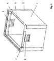
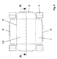
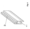
- Nachfolgend werden ein Ladungsträger und seine Herstellung an einem Beispiel näher erläutert. Es zeigen:
- Fig. 1
- Ladungsträger
- Fig. 2
- Ausgangsplatte
- Fig. 3
- Ausgangsplatte Schnitt A-A
- Fig. 4
- Stapelprofil
- Fig. 5
- Stapelecke
- Zur Lagerung und zum Transport von Kleinteilen für die Automobilproduktion sollen Kunststoffladungsträger einer Größe von 600 x 400 x 350 (L x B x H in mm) hergestellt werden.
- Für den aus Boden 10 und vier Seitenwänden 1 herzustellenden Grundkörper wird zunächst eine rechteckige, 5 mm starke Kunststoff-Hohlkammerplatte in eine Form gebracht, die etwa einem "Schweizer Kreuz" entspricht. Dies kann durch Zuschneiden oder Stanzen geschehen. Der absolut parallele Verlauf aller Kanten ist von ausschlaggebender Bedeutung.
- Die dabei abgetrennten Ecken werden weitergenutzt und entsprechend zu Eckwinkel 2 verarbeitet. Die seitlichen Kanten der Eckwinkel 2 werden dabei durch das Eindringen der V-förmigen Heizschwerter in Form einer Schräge geschlossen. Gleichzeitig werden die Teile parallel zu ihrer langen Seite mittig, mittels der Heizschwerter im 90° Winkel gekantet. Die kurzen Seiten werden stumpf vollflächig verschweißt und dabei auf Länge gebracht.
- Das zugeschnittene "Schweizer Kreuz" wird auf einer Maschine mit zwei V-förmigen Heizschwertern, die an parallel verfahrbaren Achsen befestigt sind, bearbeitet. Dabei liegt der Zuschnitt auf einer sich um 90° drehenden Grundplatte. Es erfolgen zwei unterschiedliche Bearbeitungsgänge. Zunächst wird an allen Seiten parallel im Abstand von ca. 30 mm eine Kerbung 9 eingeformt. Die Schwerter dringen dabei von oben in die Platte ein, verschweißen V-förmig die getrennten Stirnflächen und lassen auf der Plattenunterseite ein dünnes Scharnierband stehen. Es werden immer gleichzeitig beide Heizschwerter eingesetzt. Nach dem Bearbeiten der ersten beiden Seiten dreht sich der zu bearbeitende Zuschnitt auf der drehbaren Grundplatte um exakt 90°. Es erfolgt der zweite Bearbeitungsschritt zur Erzeugung der im rechten Winkel gelegenen Kerbung 9.
- Ohne ein weiteres Drehen des Werkstückes verfahren die beiden Heizschwerter exakt so weit zusammen, dass die Mitte der Schwertscheitellinien senkrecht über den zu bearbeitenden Kanten des "Schweizer Kreuzes" platziert sind. Analog der Scharnierbearbeitung tauchen die Schwerter von oben in das Werkstück ein und erzeugen eine gehrungsähnliche Schräge und Oberfläche. Noch im heißen, plastifizierten Zustand, wird das Werkstück gedreht und die entsprechenden Kanten im rechten Winkel analog bearbeitet. Auch diese Kanten werden zu Gehrungschrägen verformt. Noch im plastifizierten Zustand der vier Gehrungslinien werden die vier anhängenden Seiten an dem Basisrechteck im rechten Winkel nach oben geklappt. Die Gehrungsschrägen berühren sich im plastifizierten Zustand und verschmelzen miteinander. Es entsteht ein allseitig verschweißter Grundkasten.
- Die an den Scharnierbändern anhängenden Krempelränder 5 werden um 180° nach außen und unten geklappt. Es entsteht ein nicht umlaufender Wulst an den Behälteroberkanten. Auf die Ecken werden als Spritzgusselemente vorgefertigte Stapelecken 4 mit einem angeformten Verbindungsstück 7 aufgesteckt. Die verbleibenden Strecken zwischen den Stapelecken 4 werden dabei ohne Wulst so ergänzt, dass entsprechend abgelängte Stapelprofile 3 über die Verbindungsstücke 7 der Stapelecken 4 und über den Krempelrand 5 eingesetzt werden. Ein am Stapelprofil 3 angeformter Vorsprung 11 ermöglicht ein aufklipsen auf dem Krempelrand. Dabei fixieren die Stapelprofile 3 die vier Stapelecken 4 des Ladungsträgers, ohne weitere Verbindungstechnik, wie Verschweißen oder Verkleben. Die Stapelprofile 3 sind im beschriebenen Beispiel Stranggussteile.
- Die bearbeiteten Eckwinkel 2 werden auf ihren Innenseiten durch Hitze plastifiziert und auf die ebenso erhitzten äußeren Eckflächen des Ladungsträgers aufgedrückt. Es kommt hier zur vollflächigen Verschweißung der aufgesetzten Eckwinkel 2 mit dem Hohlkammerplatten-Grundkörper. Dabei wird eine enorme Verwindungssteifigkeit und Stapelbelastbarkeit erzeugt.
-
- 1
- Seitenwand
- 2
- Eckwinkel
- 3
- Stapelprofil
- 4
- Stapelecke
- 5
- Krempelrand
- 6
- Griff
- 7
- Verbindungsstück
- 8
- Kerbung
- 9
- Kerbung
- 10
- Boden
- 11
- Vorsprung
Claims (2)
- Verfahren zur Herstellung eines kastenförmigen Ladungsträgers aus thermoplastischem Kunststoff mit einem Boden (10) und 4 Seitenwänden (1) mit folgenden Merkmalen:- auf einer flächigen Ausgangsplatte in der vorbereiteten Form des zu fertigenden Ladungsträgers wird entlang einer vorgesehenen Kerbung mittels zwei V-förmiger Heizschwerter, die an parallel verfahrbaren Achsen befestigt sind, durch eine Plastifizierung des Kunststoffes eine Kerbe (8) erzeugt,- gleichzeitig wird entlang der zu verschweißenden Kanten mittels der Heizschwerter durch Plastifizierung des Kunststoffes eine gehrungsähnliche Schräge erzeugt,- danach erfolgt eine Drehung des Werkstückes um 90° und eine Verstellung des Abstandes der Heizschwerter auf die Länge oder Breite der um 90° versetzten Kerbung,- danach wird wieder durch Plastifizierung des Kunststoffes eine Kerbe (8) und eine gehrungsähnliche Schräge erzeugt,- anschließend werden die Seitenwände (1) um die Kerbung (8) so schnell und so weit verformt, bis sich die noch plastifizierten Kanten der jeweils benachbarten Seitenwände (1) sowie die horizontalen Gehrungskanten des Bodens (10) und der entsprechenden Seitenwände (1) berühren, miteinander verschmelzen und anschließend verfestigen.
- Verfahren nach Anspruch 1, dadurch gekennzeichnet, dass von einer um einen Krempelrand (5) erweiterten flächigen Ausgangsplatte ausgegangen wird, durch parallele Verstellung der Heizschwerter eine Kerbung (9) für den Krempelrand (5) erzeugt wird und nach einer Drehung des Werkstückes um 90° die beiden Kerbungen (9) und (8) wieder nacheinander erzeugt werden und anschließend die Krempelränder (5) um 180° nach außen umgeklappt werden.
Applications Claiming Priority (2)
| Application Number | Priority Date | Filing Date | Title |
|---|---|---|---|
| DE10335629 | 2003-08-04 | ||
| DE10335629A DE10335629B4 (de) | 2003-08-04 | 2003-08-04 | Ladungsträger aus thermoplastischem Kunststoff und Verfahren zu seiner Herstellung |
Publications (2)
| Publication Number | Publication Date |
|---|---|
| EP1505001A1 EP1505001A1 (de) | 2005-02-09 |
| EP1505001B1 true EP1505001B1 (de) | 2007-11-14 |
Family
ID=33547066
Family Applications (1)
| Application Number | Title | Priority Date | Filing Date |
|---|---|---|---|
| EP04018451A Expired - Lifetime EP1505001B1 (de) | 2003-08-04 | 2004-08-04 | Verfahren zur Herstellung eines kastenförmigen Ladungsträgers aus thermoplastischem Kunststoff |
Country Status (3)
| Country | Link |
|---|---|
| EP (1) | EP1505001B1 (de) |
| AT (1) | ATE378260T1 (de) |
| DE (2) | DE10335629B4 (de) |
Families Citing this family (9)
| Publication number | Priority date | Publication date | Assignee | Title |
|---|---|---|---|---|
| DE102009046693B4 (de) * | 2009-11-13 | 2015-02-12 | Bito-Lagertechnik Bittmann Gmbh | Stapelbarer Transport- und Lagerbehälter aus Kunststoff |
| DE102012101444A1 (de) * | 2012-02-23 | 2013-08-29 | Rehau Ag + Co | Zuschnitt zum Herstellen eines Gehäuses und Verfahren zum Herstellen eines Gehäuses aus einem derartigen Zuschnitt |
| DE102013006492A1 (de) * | 2013-04-16 | 2014-10-16 | Peter Steiner | Transportbehälter aus Leichtbauplatten |
| DE102013108062B3 (de) * | 2013-07-29 | 2014-08-14 | Christoph Dimer | Stapelbarer Lager- und Transportbehälter |
| US9527626B1 (en) | 2014-06-06 | 2016-12-27 | The Gem Group, Inc. | Pop up cargo tote |
| DE102015115592B4 (de) | 2015-09-16 | 2018-08-16 | Montara Verpacken Mit System Gmbh | Transport- und Lagerbehälter |
| DE202015104910U1 (de) | 2015-09-16 | 2015-10-21 | Montara Verpacken Mit System Gmbh | Transport- und Lagerbehälter |
| DE102019124657B3 (de) | 2019-09-13 | 2020-09-17 | Montara Verpacken Mit System Gmbh | Transport- und Lagerbehälter |
| CN116573290B (zh) * | 2023-07-10 | 2026-04-21 | 浙江利强包装科技有限公司 | 一种包装箱棱角包装器、棱角护板以及棱角包装工具 |
Family Cites Families (16)
| Publication number | Priority date | Publication date | Assignee | Title |
|---|---|---|---|---|
| FR1585381A (de) * | 1968-10-18 | 1970-01-16 | ||
| JPS51127174A (en) * | 1975-04-26 | 1976-11-05 | Sekisui Plastics | Method of manufacture of inclined box consisted of thermoplastic resin |
| ZA773918B (en) * | 1977-06-29 | 1978-12-27 | W Schedel | Container |
| DE2824700A1 (de) * | 1978-06-06 | 1979-12-20 | Reinhold Herzog Gmbh | Grundelement fuer eine zusammenlegbare kunststoffschachtel |
| DE2850558A1 (de) * | 1978-11-22 | 1980-06-04 | Licentia Gmbh | Transportbehaelter, insbesondere zum internen transport von bauteilen in der elektroindustrie |
| DE8124201U1 (de) * | 1981-08-19 | 1982-01-28 | Wager GmbH + Co, 7012 Fellbach | Faltbehaelter |
| NO900059L (no) * | 1990-01-05 | 1991-07-08 | Norsk Hydro As | Utstyr for folding og sammenfoeyning av kasser som dannes av flate eller hovedsakelig flate kasseemner. |
| DE4033646C2 (de) * | 1990-10-23 | 1995-06-29 | Wegener Gmbh | Verfahren zum stirnseitigen Verschweißen von Kunststoffteilen sowie Vorrichtung zur Durchführung dieses Verfahrens |
| US5462221A (en) * | 1995-01-04 | 1995-10-31 | Bradford Company | Tote box handle |
| DE29517978U1 (de) * | 1995-11-14 | 1996-01-04 | Lindörfer, Klaus, 75015 Bretten | Ladungsträger aus Kunststoff |
| US6056840A (en) * | 1998-03-27 | 2000-05-02 | Mills Industries, Inc. | Method and apparatus for heavy corrugated plastic construction |
| DE19833194A1 (de) * | 1998-06-06 | 1999-12-09 | Peter Goetz | Transport- und/oder Aufbewahrungsbehälter |
| DE19900718A1 (de) * | 1999-01-12 | 2000-08-03 | Bernd Siegmund | Kasten, insbesondere aus Metall |
| DE19926311A1 (de) * | 1999-04-10 | 2000-10-19 | Thomas Goetz | Transport- und/oder Aufbewahrungsbehälter |
| US6547127B2 (en) * | 2000-09-08 | 2003-04-15 | Bradford Company | Tote box with multiple piece top rail including corner pieces with projections |
| DE10107224A1 (de) * | 2001-02-16 | 2002-08-22 | Daimler Chrysler Ag | Warmbiegen eines thermoplastischen Werkstücks |
-
2003
- 2003-08-04 DE DE10335629A patent/DE10335629B4/de not_active Expired - Fee Related
-
2004
- 2004-08-04 AT AT04018451T patent/ATE378260T1/de active
- 2004-08-04 DE DE502004005472T patent/DE502004005472D1/de not_active Expired - Lifetime
- 2004-08-04 EP EP04018451A patent/EP1505001B1/de not_active Expired - Lifetime
Also Published As
| Publication number | Publication date |
|---|---|
| ATE378260T1 (de) | 2007-11-15 |
| DE10335629A1 (de) | 2005-03-17 |
| DE502004005472D1 (de) | 2007-12-27 |
| DE10335629B4 (de) | 2005-10-20 |
| EP1505001A1 (de) | 2005-02-09 |
Similar Documents
| Publication | Publication Date | Title |
|---|---|---|
| DE2900348A1 (de) | Behaelter | |
| DE3124391C2 (de) | Koffer | |
| DE102008012774A1 (de) | Halterungssystem zur horizontalen oder vertikalen Stapelung von gerahmten photovoltaischen oder solarthermischen Flachmodulen | |
| DE2133297A1 (de) | Tablettartiger,stapelbarer Behaelter und Verfahren zu dessen Herstellung | |
| DE102012220023B3 (de) | Flächenprodukt, insbesondere Faltwandungsring für einen Palettenbehälter, sowie Verfahren und Vorrichtung | |
| CH430565A (de) | Nagellose Kiste | |
| EP1505001A1 (de) | Ladungsträger aus thermoplastischem Kunststoff und Verfahren zu seiner Herstellung | |
| DE2236426C3 (de) | Formschachtel zum Aufnehmen von zerbrechlichen Gütern | |
| DE102010060810B4 (de) | Modular aufgebauter Flaschenkasten aus Kunststoff | |
| WO2011113420A2 (de) | Kantenelement und transportbox mit kantenelementen | |
| DE102006005873B4 (de) | Wandflächenteil und Transportbehälter | |
| EP1740470A2 (de) | Faltschachtel mit faltbälgen | |
| DE29517978U1 (de) | Ladungsträger aus Kunststoff | |
| DE2521539A1 (de) | Imitierte jalousietuer und verfahren zur herstellung derselben | |
| EP3127828A1 (de) | Steckverbindungselement und transportkiste mit steckverbindungselementen | |
| WO1986005159A1 (fr) | Cageot | |
| DE20312028U1 (de) | Ladungsträger aus thermoplastischem Kunststoff | |
| DE2452493B2 (de) | Verpackungseinheit für eine größere Anzahl gestapelter, sperriger Gegenstände | |
| DE102017129706B4 (de) | Rahmen für eine Transportbox | |
| DE102019207640B3 (de) | Stapelbox | |
| EP3753857A1 (de) | Wandelement eines paletten-aufsatzrahmens, und paletten-aufsatzrahmen | |
| DE19833194A1 (de) | Transport- und/oder Aufbewahrungsbehälter | |
| DE4232303C2 (de) | Verfahren zur Herstellung von Unterlagen für Gebinde, insbesondere für Flüssigkeitsbehälter, aus einem Blechzuschnitt | |
| DE69607340T2 (de) | Ausgestanzter zuschnitt für eine schalenförmige verpackung | |
| DE3145938A1 (de) | Weihnachtskalender |
Legal Events
| Date | Code | Title | Description |
|---|---|---|---|
| PUAI | Public reference made under article 153(3) epc to a published international application that has entered the european phase |
Free format text: ORIGINAL CODE: 0009012 |
|
| AK | Designated contracting states |
Kind code of ref document: A1 Designated state(s): AT BE BG CH CY CZ DE DK EE ES FI FR GB GR HU IE IT LI LU MC NL PL PT RO SE SI SK TR |
|
| AX | Request for extension of the european patent |
Extension state: AL HR LT LV MK |
|
| 17P | Request for examination filed |
Effective date: 20050801 |
|
| AKX | Designation fees paid |
Designated state(s): AT BE BG CH CY CZ DE DK EE ES FI FR GB GR HU IE IT LI LU MC NL PL PT RO SE SI SK TR |
|
| 17Q | First examination report despatched |
Effective date: 20051215 |
|
| RIC1 | Information provided on ipc code assigned before grant |
Ipc: B65D 21/032 20060101ALN20070222BHEP Ipc: B31B 3/26 20060101ALI20070222BHEP Ipc: B65D 1/22 20060101AFI20070222BHEP Ipc: B31B 3/64 20060101ALI20070222BHEP Ipc: B29C 53/06 20060101ALI20070222BHEP Ipc: B31B 1/25 20060101ALI20070222BHEP |
|
| RTI1 | Title (correction) |
Free format text: PROCESS FOR MANUFACTURING A BOX-SHAPED CONTAINER MADE OF THERMOPLASTIC MATERIAL |
|
| GRAP | Despatch of communication of intention to grant a patent |
Free format text: ORIGINAL CODE: EPIDOSNIGR1 |
|
| GRAS | Grant fee paid |
Free format text: ORIGINAL CODE: EPIDOSNIGR3 |
|
| GRAA | (expected) grant |
Free format text: ORIGINAL CODE: 0009210 |
|
| AK | Designated contracting states |
Kind code of ref document: B1 Designated state(s): AT BE BG CH CY CZ DE DK EE ES FI FR GB GR HU IE IT LI LU MC NL PL PT RO SE SI SK TR |
|
| REG | Reference to a national code |
Ref country code: GB Ref legal event code: FG4D Free format text: NOT ENGLISH |
|
| REG | Reference to a national code |
Ref country code: CH Ref legal event code: EP |
|
| REG | Reference to a national code |
Ref country code: IE Ref legal event code: FG4D Free format text: LANGUAGE OF EP DOCUMENT: GERMAN |
|
| REF | Corresponds to: |
Ref document number: 502004005472 Country of ref document: DE Date of ref document: 20071227 Kind code of ref document: P |
|
| PG25 | Lapsed in a contracting state [announced via postgrant information from national office to epo] |
Ref country code: SE Free format text: LAPSE BECAUSE OF FAILURE TO SUBMIT A TRANSLATION OF THE DESCRIPTION OR TO PAY THE FEE WITHIN THE PRESCRIBED TIME-LIMIT Effective date: 20080214 Ref country code: ES Free format text: LAPSE BECAUSE OF FAILURE TO SUBMIT A TRANSLATION OF THE DESCRIPTION OR TO PAY THE FEE WITHIN THE PRESCRIBED TIME-LIMIT Effective date: 20080225 Ref country code: NL Free format text: LAPSE BECAUSE OF FAILURE TO SUBMIT A TRANSLATION OF THE DESCRIPTION OR TO PAY THE FEE WITHIN THE PRESCRIBED TIME-LIMIT Effective date: 20071114 |
|
| NLV1 | Nl: lapsed or annulled due to failure to fulfill the requirements of art. 29p and 29m of the patents act | ||
| PG25 | Lapsed in a contracting state [announced via postgrant information from national office to epo] |
Ref country code: FI Free format text: LAPSE BECAUSE OF FAILURE TO SUBMIT A TRANSLATION OF THE DESCRIPTION OR TO PAY THE FEE WITHIN THE PRESCRIBED TIME-LIMIT Effective date: 20071114 Ref country code: BG Free format text: LAPSE BECAUSE OF FAILURE TO SUBMIT A TRANSLATION OF THE DESCRIPTION OR TO PAY THE FEE WITHIN THE PRESCRIBED TIME-LIMIT Effective date: 20080214 Ref country code: SI Free format text: LAPSE BECAUSE OF FAILURE TO SUBMIT A TRANSLATION OF THE DESCRIPTION OR TO PAY THE FEE WITHIN THE PRESCRIBED TIME-LIMIT Effective date: 20071114 Ref country code: PL Free format text: LAPSE BECAUSE OF FAILURE TO SUBMIT A TRANSLATION OF THE DESCRIPTION OR TO PAY THE FEE WITHIN THE PRESCRIBED TIME-LIMIT Effective date: 20071114 |
|
| GBV | Gb: ep patent (uk) treated as always having been void in accordance with gb section 77(7)/1977 [no translation filed] | ||
| PG25 | Lapsed in a contracting state [announced via postgrant information from national office to epo] |
Ref country code: DK Free format text: LAPSE BECAUSE OF FAILURE TO SUBMIT A TRANSLATION OF THE DESCRIPTION OR TO PAY THE FEE WITHIN THE PRESCRIBED TIME-LIMIT Effective date: 20071114 Ref country code: CZ Free format text: LAPSE BECAUSE OF FAILURE TO SUBMIT A TRANSLATION OF THE DESCRIPTION OR TO PAY THE FEE WITHIN THE PRESCRIBED TIME-LIMIT Effective date: 20071114 |
|
| EN | Fr: translation not filed | ||
| PG25 | Lapsed in a contracting state [announced via postgrant information from national office to epo] |
Ref country code: RO Free format text: LAPSE BECAUSE OF FAILURE TO SUBMIT A TRANSLATION OF THE DESCRIPTION OR TO PAY THE FEE WITHIN THE PRESCRIBED TIME-LIMIT Effective date: 20071114 Ref country code: SK Free format text: LAPSE BECAUSE OF FAILURE TO SUBMIT A TRANSLATION OF THE DESCRIPTION OR TO PAY THE FEE WITHIN THE PRESCRIBED TIME-LIMIT Effective date: 20071114 |
|
| PLBE | No opposition filed within time limit |
Free format text: ORIGINAL CODE: 0009261 |
|
| STAA | Information on the status of an ep patent application or granted ep patent |
Free format text: STATUS: NO OPPOSITION FILED WITHIN TIME LIMIT |
|
| PG25 | Lapsed in a contracting state [announced via postgrant information from national office to epo] |
Ref country code: PT Free format text: LAPSE BECAUSE OF FAILURE TO SUBMIT A TRANSLATION OF THE DESCRIPTION OR TO PAY THE FEE WITHIN THE PRESCRIBED TIME-LIMIT Effective date: 20080414 |
|
| REG | Reference to a national code |
Ref country code: IE Ref legal event code: FD4D |
|
| 26N | No opposition filed |
Effective date: 20080815 |
|
| PG25 | Lapsed in a contracting state [announced via postgrant information from national office to epo] |
Ref country code: IE Free format text: LAPSE BECAUSE OF FAILURE TO SUBMIT A TRANSLATION OF THE DESCRIPTION OR TO PAY THE FEE WITHIN THE PRESCRIBED TIME-LIMIT Effective date: 20071114 Ref country code: FR Free format text: LAPSE BECAUSE OF FAILURE TO SUBMIT A TRANSLATION OF THE DESCRIPTION OR TO PAY THE FEE WITHIN THE PRESCRIBED TIME-LIMIT Effective date: 20080829 |
|
| PG25 | Lapsed in a contracting state [announced via postgrant information from national office to epo] |
Ref country code: GB Free format text: LAPSE BECAUSE OF FAILURE TO SUBMIT A TRANSLATION OF THE DESCRIPTION OR TO PAY THE FEE WITHIN THE PRESCRIBED TIME-LIMIT Effective date: 20071114 |
|
| PG25 | Lapsed in a contracting state [announced via postgrant information from national office to epo] |
Ref country code: GR Free format text: LAPSE BECAUSE OF FAILURE TO SUBMIT A TRANSLATION OF THE DESCRIPTION OR TO PAY THE FEE WITHIN THE PRESCRIBED TIME-LIMIT Effective date: 20080215 |
|
| PG25 | Lapsed in a contracting state [announced via postgrant information from national office to epo] |
Ref country code: MC Free format text: LAPSE BECAUSE OF NON-PAYMENT OF DUE FEES Effective date: 20080831 |
|
| PG25 | Lapsed in a contracting state [announced via postgrant information from national office to epo] |
Ref country code: EE Free format text: LAPSE BECAUSE OF FAILURE TO SUBMIT A TRANSLATION OF THE DESCRIPTION OR TO PAY THE FEE WITHIN THE PRESCRIBED TIME-LIMIT Effective date: 20071114 |
|
| PG25 | Lapsed in a contracting state [announced via postgrant information from national office to epo] |
Ref country code: BE Free format text: LAPSE BECAUSE OF NON-PAYMENT OF DUE FEES Effective date: 20080831 Ref country code: CY Free format text: LAPSE BECAUSE OF FAILURE TO SUBMIT A TRANSLATION OF THE DESCRIPTION OR TO PAY THE FEE WITHIN THE PRESCRIBED TIME-LIMIT Effective date: 20071114 |
|
| PG25 | Lapsed in a contracting state [announced via postgrant information from national office to epo] |
Ref country code: LU Free format text: LAPSE BECAUSE OF NON-PAYMENT OF DUE FEES Effective date: 20080804 Ref country code: HU Free format text: LAPSE BECAUSE OF FAILURE TO SUBMIT A TRANSLATION OF THE DESCRIPTION OR TO PAY THE FEE WITHIN THE PRESCRIBED TIME-LIMIT Effective date: 20080515 |
|
| PG25 | Lapsed in a contracting state [announced via postgrant information from national office to epo] |
Ref country code: TR Free format text: LAPSE BECAUSE OF FAILURE TO SUBMIT A TRANSLATION OF THE DESCRIPTION OR TO PAY THE FEE WITHIN THE PRESCRIBED TIME-LIMIT Effective date: 20071114 |
|
| PG25 | Lapsed in a contracting state [announced via postgrant information from national office to epo] |
Ref country code: IT Free format text: LAPSE BECAUSE OF NON-PAYMENT OF DUE FEES Effective date: 20080831 |
|
| PGFP | Annual fee paid to national office [announced via postgrant information from national office to epo] |
Ref country code: CH Payment date: 20110824 Year of fee payment: 8 |
|
| PGFP | Annual fee paid to national office [announced via postgrant information from national office to epo] |
Ref country code: AT Payment date: 20110822 Year of fee payment: 8 |
|
| REG | Reference to a national code |
Ref country code: CH Ref legal event code: PL |
|
| REG | Reference to a national code |
Ref country code: AT Ref legal event code: MM01 Ref document number: 378260 Country of ref document: AT Kind code of ref document: T Effective date: 20120804 |
|
| PG25 | Lapsed in a contracting state [announced via postgrant information from national office to epo] |
Ref country code: LI Free format text: LAPSE BECAUSE OF NON-PAYMENT OF DUE FEES Effective date: 20120831 Ref country code: CH Free format text: LAPSE BECAUSE OF NON-PAYMENT OF DUE FEES Effective date: 20120831 |
|
| PG25 | Lapsed in a contracting state [announced via postgrant information from national office to epo] |
Ref country code: AT Free format text: LAPSE BECAUSE OF NON-PAYMENT OF DUE FEES Effective date: 20120804 |
|
| REG | Reference to a national code |
Ref country code: DE Ref legal event code: R082 Ref document number: 502004005472 Country of ref document: DE Representative=s name: PATENTANWAELTE PAETZELT - SELTMANN - HOFMANN, DE |
|
| REG | Reference to a national code |
Ref country code: DE Ref legal event code: R082 Ref document number: 502004005472 Country of ref document: DE Representative=s name: PATENTANWAELTE PAETZELT - SELTMANN - HOFMANN, DE Effective date: 20140926 Ref country code: DE Ref legal event code: R081 Ref document number: 502004005472 Country of ref document: DE Owner name: MONTARA VERPACKEN MIT SYSTEM GMBH, DE Free format text: FORMER OWNER: DIMER, CHRISTOPH, 14513 TELTOW, DE Effective date: 20140926 |
|
| PGFP | Annual fee paid to national office [announced via postgrant information from national office to epo] |
Ref country code: DE Payment date: 20150828 Year of fee payment: 12 |
|
| REG | Reference to a national code |
Ref country code: DE Ref legal event code: R119 Ref document number: 502004005472 Country of ref document: DE |
|
| PG25 | Lapsed in a contracting state [announced via postgrant information from national office to epo] |
Ref country code: DE Free format text: LAPSE BECAUSE OF NON-PAYMENT OF DUE FEES Effective date: 20170301 |