EP1504130B1 - Vorrichtung zur durchlaufbehandlung von flüssigmetall mittels gas und filtration - Google Patents
Vorrichtung zur durchlaufbehandlung von flüssigmetall mittels gas und filtration Download PDFInfo
- Publication number
- EP1504130B1 EP1504130B1 EP03749924A EP03749924A EP1504130B1 EP 1504130 B1 EP1504130 B1 EP 1504130B1 EP 03749924 A EP03749924 A EP 03749924A EP 03749924 A EP03749924 A EP 03749924A EP 1504130 B1 EP1504130 B1 EP 1504130B1
- Authority
- EP
- European Patent Office
- Prior art keywords
- treatment
- treatment device
- liquid metal
- space
- compartment
- Prior art date
- Legal status (The legal status is an assumption and is not a legal conclusion. Google has not performed a legal analysis and makes no representation as to the accuracy of the status listed.)
- Expired - Lifetime
Links
Images


Classifications
-
- B—PERFORMING OPERATIONS; TRANSPORTING
- B22—CASTING; POWDER METALLURGY
- B22D—CASTING OF METALS; CASTING OF OTHER SUBSTANCES BY THE SAME PROCESSES OR DEVICES
- B22D1/00—Treatment of fused masses in the ladle or the supply runners before casting
- B22D1/002—Treatment with gases
-
- C—CHEMISTRY; METALLURGY
- C22—METALLURGY; FERROUS OR NON-FERROUS ALLOYS; TREATMENT OF ALLOYS OR NON-FERROUS METALS
- C22B—PRODUCTION AND REFINING OF METALS; PRETREATMENT OF RAW MATERIALS
- C22B21/00—Obtaining aluminium
- C22B21/06—Obtaining aluminium refining
- C22B21/064—Obtaining aluminium refining using inert or reactive gases
-
- C—CHEMISTRY; METALLURGY
- C22—METALLURGY; FERROUS OR NON-FERROUS ALLOYS; TREATMENT OF ALLOYS OR NON-FERROUS METALS
- C22B—PRODUCTION AND REFINING OF METALS; PRETREATMENT OF RAW MATERIALS
- C22B21/00—Obtaining aluminium
- C22B21/06—Obtaining aluminium refining
- C22B21/066—Treatment of circulating aluminium, e.g. by filtration
-
- C—CHEMISTRY; METALLURGY
- C22—METALLURGY; FERROUS OR NON-FERROUS ALLOYS; TREATMENT OF ALLOYS OR NON-FERROUS METALS
- C22B—PRODUCTION AND REFINING OF METALS; PRETREATMENT OF RAW MATERIALS
- C22B9/00—General processes of refining or remelting of metals; Apparatus for electroslag or arc remelting of metals
- C22B9/05—Refining by treating with gases, e.g. gas flushing also refining by means of a material generating gas in situ
- C22B9/055—Refining by treating with gases, e.g. gas flushing also refining by means of a material generating gas in situ while the metal is circulating, e.g. combined with filtration
Definitions
- the invention relates to a device for treating a flow of liquid metal, in particular aluminum, an aluminum alloy, magnesium or a magnesium alloy.
- liquid metal It is known to treat a liquid metal stream or batch before casting it as a metallurgical product, such as a shaped part, a billet or a plate.
- the treatment of liquid metal generally aims to remove dissolved gases (including hydrogen), dissolved impurities (including alkali metals) and solid or liquid inclusions that could affect the quality of the cast products.
- This treatment typically comprises a treatment operation by insufflation of a gas in the liquid metal, which operation is performed in a first pocket.
- the process gas may be inert and insoluble in the liquid metal (such as argon) or reactant (such as chlorine), or a mixture thereof.
- the inert and insoluble gas absorbs the dissolved gas by dilution effect and carries it with it.
- the reactive gas reacts with certain dissolved impurities and thus generates liquid or solid inclusions which, like those already present in the liquid metal, can be removed by a filtering operation in a second bag provided with a filter, such as a bag deep bed filtration, called "deep bed filter” in English.
- a filter such as a bag deep bed filtration, called "deep bed filter” in English.
- known liquid metal processing systems have several disadvantages.
- the known systems are bulky installations whose maintenance is generally complicated. Such systems represent an expensive initial investment and generate significant operating costs.
- U.S. Patent No. 5,846,479 discloses an in-line processing system comprising a closed process chamber and a series of process gas injection nozzles disposed in line along the lateral sides of the compartment. This system does not eliminate solid inclusions.
- FR-A-2,039,232 discloses an in-line liquid metal processing system, with a filter located in an outlet duct, outside the treatment compartment.
- EP-A-291580 discloses another system provided with gas injection means and filter means and wherein the liquid metal flows vertically.
- the Applicant has sought a compact liquid metal processing device that provides an industrial and economic solution to the disadvantages of the devices of the prior art.
- the subject of the invention is a device for treating a flow of liquid metal comprising a treatment bag comprising fixed injection means and located in the upstream portion of the treatment bag and at least one filtration means in its part. downstream.
- the applicant has had the idea of grouping the injection means of the treatment gases and the filtration means inside a compact treatment compartment. This grouping makes it possible to considerably reduce the complexity of the liquid metal processing system and to facilitate their maintenance.
- the applicant furthermore had the idea that the combination of these means of treatment in the same compartment could lead to an improvement of the treatment by the fact that, on the one hand, the mixing of the liquid metal caused by the insufflation gas in it avoids the accumulation of solid material near the filtration means (and in particular on the surface of the (or) slab (s) filtration when using these filtration means) and that on the other hand, the filtration means promotes the formation of recirculating flow of the liquid metal inside the compartment which tend to increase the residence time and the effectiveness of the treatment.
- the invention also relates to the use of said device for the treatment of a liquid metal stream.
- Said liquid metal is typically selected from the group consisting of aluminum, aluminum alloys, magnesium or a magnesium alloy.
- the device (1) for treating a flow of liquid metal comprises a treatment bag (2) comprising a treatment compartment (20), input means (7, 9) and outlet (8, 10) of the liquid metal, connection means (11, 12, 13, 14) to at least one supply channel (15) of liquid metal and at least one discharge channel (16).
- said means for inlet and outlet of the liquid metal each comprising at least one orifice (9, 10) which is positioned so as to be entirely below the level (26) of the liquid metal during the treatment, in order to prevent the introduction of ambient air in the compartment being treated, and is characterized in that said treatment compartment (20) comprises an upstream portion (23) and a downstream part (24), in that said injection means (22, 22a, 22b) are located in said upstream part (23) and in that said compartment (20) further comprises at least one first filtration means (40) located in said downstream portion (24).
- the main longitudinal axis (6) of the device of the invention is substantially horizontal during processing.
- the average flow of the liquid metal in the device of the invention being processed is also essentially horizontal.
- the device according to the invention can thus be inserted into a liquid metal flow system from a holding bag to the casting device via open chutes.
- the absence of a significant difference in level between the inlet and the outlet of the device makes it possible to simplify the flow system of the liquid metal and to avoid the risks of overflow of the liquid metal.
- the theoretical free surface of the liquid metal being treated is represented by a hatched line 26. It goes without saying that the free surface of the liquid metal is generally not flat inside the treatment compartment, in that the gas bubbles cause deformation of this surface during treatment.
- the level (26) of the liquid metal is defined as the average level of the free surface of the liquid metal that would be observed without the injection of the process gas.
- the level (26) of the liquid metal is typically substantially constant in the process compartment. In other words, the level (26 ') of the liquid metal in the upstream portion (23) of said compartment is preferably typically substantially the same as the level (26 ") of the liquid metal in the downstream portion (24) of said compartment .
- Said inlet (7, 9) and outlet (8, 10) means of the liquid metal are arranged so that, during treatment, the level (26e) of the liquid metal at the inlet of the device is substantially the same as the level (26s) of the liquid metal at the output of the device.
- substantially the same level means that the difference in level is less than about 1 cm.
- the levels Ne and Ns of the bottoms (37, 38) of the supply (15) and discharge (16) of the device of the invention are typically substantially the same level.
- Levels Ne and Ns are typically between 20 and 50% of the average height H of the liquid metal contained in the treatment compartment being treated.
- the orifices (9, 10) are preferably located near the bottom (28) of said compartment to promote a more efficient treatment of the liquid metal and to simplify the emptying of the treatment compartment. More specifically, the bottom of the inlet (9) or outlet (10) orifice is preferably at a distance of less than about 10 cm, and more preferably less than about 5 cm, from the bottom (28) of the upstream portion (23) of the treatment compartment (20).
- the orifices (9, 10) typically correspond to an end of openings or ducts (7, 8) provided in the opposite end walls (29, 30) of the pocket. (2).
- These orifices may optionally be formed by more complex arrangements comprising, for example, a baffle.
- the pocket (2) typically comprises a metal box (3) and an inner lining (4) of refractory material.
- the coating (4) can be preformed.
- the pocket advantageously comprises at least one drain (21), which is preferably located near the bottom (28) of the pocket (2).
- the drain may be upstream or downstream of the (or) slab (s) (40, 41). It may be advantageous to provide a drain in the upstream portion (23) of the treatment compartment and a drain in the downstream portion (24) of the treatment compartment to ensure complete emptying of the bag after the treatment operation.
- the bottom (28) may optionally be inclined relative to the main axis (6) of the device.
- the pocket (2) is typically closed, in its upper part, with a cover (5) removable.
- the lid typically includes a metal shell (34) and a refractory liner (35).
- the lid is advantageously provided with a gripping means (27) to be able to put it in place and remove it easily, generally using mechanized means.
- the device (1) advantageously comprises sealing means to prevent gas exchange between the inside and the outside of said compartment (20), such as a seal (36) between the cover (5) and the box ( 3).
- the treatment bag (2) and / or the lid (5) can be provided with means (19) for evacuating the treatment gas, such as a pipe made of refractory material.
- the "raw” liquid metal (17) enters the process chamber (20) through the inlet port (9) while the “treated” metal (18) exits said compartment (20). ) through the outlet (10).
- the raw metal enters at the left end (E) of the device and the treated metal exits at the right end (S) of the device.
- the liquid metal inlet (9) and outlet (10) ports are located on two opposite faces (29, 30) of the device.
- This configuration corresponds to a rectilinear arrangement. It is also possible, according to the invention, to arrange the inlet and / or the outlet on other faces of the device, so that they can be, for example, perpendicular or parallel to each other.
- the injection means (22, 22a, 22b) are preferably located in at least one side wall (32, 33) of the pocket (2).
- the injection means are advantageously placed on at least one of the lateral sides of the treatment compartment (20) of the pocket (2), and more precisely in at least one of the side walls (32, 33). said compartment, which walls are substantially perpendicular to the flow of liquid metal. This choice makes it possible to arrange several injection means along the metal stream and thus to ensure greater treatment efficiency.
- the injection means (22, 22a, 22b) are typically placed in both side walls (32, 33) of the treatment compartment (20).
- the injection means (22, 22a, 22b) are typically arranged in line and preferably located near the bottom (28) of the treatment compartment (20) to allow gas insufflation in most of the metal volume. liquid included in the upstream portion (23) of said compartment.
- the height of the injection means relative to the bottom of the treatment compartment is typically between 2 and 6 cm.
- injection means (22, 22a, 22b) only in the upstream portion (23) of the treatment compartment (20). It is particularly advantageous to locate the injection means (22, 22a, 22b) in the flow of liquid metal emerging from the inlet port (9), so as to increase the volume of liquid metal effectively treated.
- the injection means (22, 22a, 22b) are typically nozzles, which can be fixed or adjustable.
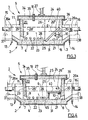
- the injection means (22, 22a, 22b) are alternately in the two side walls (32, 33) of the treatment compartment (20), that is to say on both sides of the treatment compartment. Said means are not then vis-à-vis, which allows that the gas jets do not impact directly.
- the injection means (22a) which are placed on one side of said compartment (20) are offset longitudinally (that is to say in the long direction of the device) relative to the injection means (22b) which are placed on the other side of said compartment (20).
- the injection means are typically in line on each side of the treatment compartment.
- the number of injection means is typically between 3 and 10 on each side of said compartment. They are typically spaced 10 to 20 cm apart.
- the injection means (22, 22a, 22b) are preferably such that they do not form protuberances inside the treatment compartment, so as to allow easy maintenance of the latter.
- the injection means (22, 22a, 22b) take the form of nozzles, or similar systems, they can be arranged recessed in the wall of said compartment.
- the end of the nozzles is preferably of refractory material, such as sialon (aluminum oxynitride and silicon).
- the injection means (22, 22a, 22b) are normally fixed during the treatment, in that they do not undergo displacement and / or rotation.
- Their orientation may, however, be variable in order to allow a finer adjustment of the efficiency of the injection of gas into the liquid metal.
- the injection means (22, 22a, 22b) may optionally make it possible to inject the treatment gas with a particular orientation with respect to the bottom (28) of said compartment.
- the treatment gas is typically injected with an angle ⁇ between 0 ° and 25 ° relative to the bottom (28).
- the injection means are preferably such that their total flow rate of treatment gas of the injection means is greater than about 5 Nm 3 / hour (typically between 8 and 10 m 3 / hour). This result can be obtained using a plurality of localized injection means, preferably near the bottom of said compartment (typically at a distance from the bottom of between 2 and 6 cm).
- Each filtration means (40, 41) is placed in the downstream part and inside the treatment compartment (20). It serves to prevent inclusions from passing into the liquid metal stream (18) exiting the device.
- Each filtration means (40, 41) is preferably a filtration slab to allow easy change thereof.
- the slab typically comprises a rigid ceramic foam, such as a CFF ("ceramic foam filter”), and is typically alumina.
- the porosity of the slab is preferably greater than 10 ppi ("pores per inch”) (corresponding to 4 pores per cm), and typically between 30 and 40 ppi (corresponding to 12 to 16 pores per cm), in order to allow easy priming of the filtration.
- the thickness of each slab is typically between 2 and 5 cm and its length L is typically between 30 and 50 cm.
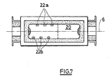
- the device comprises a single filtration slab (40) whose width W is typically at least equal to the width Wo of said compartment and whose length L is typically at least equal to the height H of liquid metal in said compartment.
- the length L thereof is preferably such that it extends almost to the lid (and therefore approximately equal to the height Ho of the internal cavity of the compartment (20)).
- the filtration slabs can be held in place by grooves in the wall of the treatment compartment.
- the device comprises at least a second filtration slab (41) disposed downstream of the first slab (40) (that is to say that the slabs ( 40, 41) are then arranged in series). These slabs are typically substantially parallel to each other. This variant of the invention can make it possible to change a slab without interrupting the treatment.
- the filtration slab (40) arranged to be entirely in the liquid metal during the treatment, which makes it possible to use the entire surface of the slab for filtration.
- Each filtration slab (40) can be inclined at an angle ⁇ with respect to the vertical (that is to say with respect to a line perpendicular to the main axis (6) of the compartment device), in order to increase the filtration area and the metal flow.
- the angle ⁇ is typically between 20 ° and 90 °.
- the slab may optionally be arranged horizontally (the angle ⁇ is then equal to 90 °).
- the device according to the invention may further comprise a baffle (42) between the upstream portion (23) of said compartment (20) and the first filtration means (40), so as to limit the turbulence close to the surface of said first filter means (40), as shown in FIG.
- the filtration means are easy to change.
- the dividing line (25) between the upstream gas injection liquid metal processing zone (23) and the downstream metal filtration processing zone (24) is approximate. It goes without saying that gas injection treatment can extend slightly beyond this line.
- the length Lg of the upstream portion (23) of the treatment compartment (20) is typically 30% to 90%, and preferably 50 to 80%, of the internal length Lo of said compartment.
- the length Lf of the downstream portion (24) of the treatment compartment (20) then typically corresponds to 20 to 50% of the length Lo of said compartment.
- the invention has the advantage of reducing the length of the chutes and of reducing the exposure of the metal to the ambient air, which can in particular lead to a recovery of hydrogen.
- the preheating of the treatment device is done in a single operation, that is to say that it is no longer necessary to preheat separately a gas treatment bag and a filtration bag, which makes it possible to reduce costs (in particular, a single burner can be used for this operation). Operating costs can also be reduced by the fact that coating changes need only be made on a single processing device.
- the device of the invention can be opened during treatment, without interrupting it, in order to remove accumulated dirt on the surface of the liquid metal and / or to change a filtration slab.
- the internal volume of the treatment compartment Vo can be very small in comparison with the known degassing treatment devices comprising a bag (the volume Vo of the device according to the invention is typically between 0.1 m 3 and 0.2 m 3 then that the known devices have an internal volume typically between 0.5 and 1 m 3 ).
- the device of the invention makes it possible to treat with a high efficiency (typically superior at 40%) a volume V of liquid metal as low as 0.1 m 3 to 0.2 m 3 with a flow rate greater than or equal to 30 tons / hour.
- the compactness of the treatment compartment (20) and the high flow rate of the device of the invention make it possible to prevent the cooling of the liquid metal during treatment.
Landscapes
- Engineering & Computer Science (AREA)
- Chemical & Material Sciences (AREA)
- Mechanical Engineering (AREA)
- Organic Chemistry (AREA)
- Materials Engineering (AREA)
- Metallurgy (AREA)
- Manufacturing & Machinery (AREA)
- Manufacture And Refinement Of Metals (AREA)
- Electrical Discharge Machining, Electrochemical Machining, And Combined Machining (AREA)
- Casting Support Devices, Ladles, And Melt Control Thereby (AREA)
- Treatment Of Steel In Its Molten State (AREA)
- Sampling And Sample Adjustment (AREA)
- Filtration Of Liquid (AREA)
- Filtering Materials (AREA)
Claims (18)
- Vorrichtung zur Behandlung (1) eines flüssigen Metallstroms, bestehend aus einer Behandlungspfanne (2), die einen Behandlungsraum (20), Mittel zum Einlassen (7, 9) und Ablassen (8, 10) des flüssigen Metalls, Mittel zum Anschluss (11, 12, 13, 14) an mindestens eine Rinne zum Beschicken (15) mit flüssigem Metall und an mindestens eine Rinne zum Ableiten (16) des flüssigen Metalls und Mittel zum Einspritzen (22, 22a, 22b) eines Behandlungsgases in das flüssige Metall, die an mindestens einer Seitenwand (32, 33) der Pfanne (2) angeordnet sind, aufweist, wobei die genannten Mittel zum Einlassen und Ablassen des flüssigen Metalls jeweils mindestens eine Öffnung (9, 10) aufweisen, die derart positioniert ist, dass sie sich während der Behandlung vollständig unter dem Pegel (26) des flüssigen Metalls befindet, um das Eindringen von Umgebungsluft in den genannten Raum bei der Behandlung zu verhindern, und dadurch gekennzeichnet, dass der genannte Behandlungsraum (20) einen stromaufseitigen Teil (23) und einen stromabseitigen Teil (24) aufweist, dass die genannten Einspritzmittel (22, 22a, 22b) sich in dem genannten stromaufseitigen Teil (23) befinden, dass der genannte Raum (20) ferner mindestens ein erstes Filtermittel (40), welches sich in dem genannten stromabseitigen Teil (24) befindet, aufweist und dass die genannten Öffnungen (9, 10) sich in der Nähe des Bodens (28) des genannten Raums befinden.
- Behandlungsvorrichtung (1) nach Anspruch 1, dadurch gekennzeichnet, dass die Öffnungen zum Einlassen (9) und Ablassen (10) des flüssigen Metalls sich in den gegenüberliegenden Endwänden (29, 30) der Pfanne (2) befinden.
- Behandlungsvorrichtung (1) nach einem der Ansprüche 1 oder 2, dadurch gekennzeichnet, dass die Einspritzmittel (22, 22a, 22b) sich in der Nähe des Bodens (28) des Behandlungsraums (20) befinden.
- Behandlungsvorrichtung (1) nach einem der Ansprüche 1 bis 3, dadurch gekennzeichnet, dass die Einspritzmittel (22, 22a, 22b) in einer Reihe angeordnet sind.
- Behandlungsvorrichtung (1) nach einem der Ansprüche 1 bis 4, dadurch gekennzeichnet, dass die Einspritzmittel (22, 22a, 22b) an den beiden Seitenwänden (32, 33) des Behandlungsraums (20) positioniert sind.
- Behandlungsvorrichtung (1) nach Anspruch 5, dadurch gekennzeichnet, dass die Einspritzmittel (22, 22a, 22b) wechselseitig an den beiden Seitenwänden (32, 33) des Behandlungsraums (20) angeordnet sind.
- Behandlungsvorrichtung (1) nach einem der Ansprüche 1 bis 6, dadurch gekennzeichnet, dass die Einspritzmittel (22, 22a, 22b) Düsen sind.
- Behandlungsvorrichtung (1) nach einem der Ansprüche 1 bis 7, dadurch gekennzeichnet, dass die Einspritzmittel (22, 22a, 22b) schwenkbar sind.
- Behandlungsvorrichtung (1) nach einem der Ansprüche 1 bis 8, dadurch gekennzeichnet, dass das erste Filtermittel (40) eine Platte ist.
- Behandlungsvorrichtung (1) nach Anspruch 9, dadurch gekennzeichnet, dass die Platte einen starren Keramikschaum aufweist.
- Behandlungsvorrichtung (1) nach Anspruch 10, dadurch gekennzeichnet, dass die Porosität des starren Keramikschaums größer als 4 Poren pro cm ist.
- Behandlungsvorrichtung (1) nach einem der Ansprüche 9 bis 11, dadurch gekennzeichnet, dass sie mindestens eine zweite Filterplatte (41) aufweist, die hinter der ersten Platte (40) angeordnet ist.
- Behandlungsvorrichtung (1) nach einem der Ansprüche 9 bis 12, dadurch gekennzeichnet, dass jede Platte einen Winkel α zu einer senkrecht zur Hauptachse (6) des genannten Raumes verlaufenden Linie bildet und dass dieser Winkel zwischen 20° und 90° liegt.
- Behandlungsvorrichtung (1) nach einem der Ansprüche 1 bis 13, dadurch gekennzeichnet, dass sie ein Hindernis (42) zwischen dem stromaufseitigen Teil (23) des genannten Raumes (20) und dem ersten Filtermittel (40) aufweist, sodass die Wirbelströmungen in der Nähe der Oberfläche dieses Filtermittels begrenzt werden.
- Behandlungsvorrichtung (1) nach einem der Ansprüche 1 bis 14, dadurch gekennzeichnet, dass die Länge Lg des stromaufseitigen Teils (23) des Behandlungsraums (20) 30 bis 90% der Innenlänge Lo des genannten Raumes entspricht.
- Behandlungsvorrichtung (1) nach einem der Ansprüche 1 bis 14, dadurch gekennzeichnet, dass die Länge Lg des stromaufseitigen Teils (23) des Behandlungsraums (20) 50 bis 80% der Innenlänge Lo des genannten Raumes entspricht.
- Verwendung der Behandlungsvorrichtung (1) nach einem der Ansprüche 1 bis 16 für die Behandlung eines flüssigen Metallstroms.
- Verwendung nach Anspruch 17, dadurch gekennzeichnet, dass das genannte Metall aus der Gruppe bestehend aus Aluminium, Aluminiumlegierungen, Magnesium oder einer Magnesiumlegierung ausgewählt wird.
Priority Applications (1)
| Application Number | Priority Date | Filing Date | Title |
|---|---|---|---|
| SI200330545T SI1504130T1 (sl) | 2002-05-13 | 2003-05-06 | Naprava za kontinuirno obdelavo tekoce kovine s plinom in filtriranjem |
Applications Claiming Priority (3)
| Application Number | Priority Date | Filing Date | Title |
|---|---|---|---|
| FR0205867A FR2839518B1 (fr) | 2002-05-13 | 2002-05-13 | Dispositif de traitement en ligne de metal liquide |
| FR0205867 | 2002-05-13 | ||
| PCT/FR2003/001399 WO2003095686A1 (fr) | 2002-05-13 | 2003-05-06 | Dispositif de traitement en ligne de metal liquide par voie gazeuse et par filtration |
Publications (2)
| Publication Number | Publication Date |
|---|---|
| EP1504130A1 EP1504130A1 (de) | 2005-02-09 |
| EP1504130B1 true EP1504130B1 (de) | 2006-09-06 |
Family
ID=29286442
Family Applications (1)
| Application Number | Title | Priority Date | Filing Date |
|---|---|---|---|
| EP03749924A Expired - Lifetime EP1504130B1 (de) | 2002-05-13 | 2003-05-06 | Vorrichtung zur durchlaufbehandlung von flüssigmetall mittels gas und filtration |
Country Status (12)
| Country | Link |
|---|---|
| US (1) | US7648674B2 (de) |
| EP (1) | EP1504130B1 (de) |
| AT (1) | ATE338832T1 (de) |
| AU (1) | AU2003255561A1 (de) |
| BR (1) | BR0310028A (de) |
| DE (1) | DE60308173T2 (de) |
| ES (1) | ES2271627T3 (de) |
| FR (1) | FR2839518B1 (de) |
| PL (1) | PL198450B1 (de) |
| PT (1) | PT1504130E (de) |
| RU (1) | RU2301274C2 (de) |
| WO (1) | WO2003095686A1 (de) |
Families Citing this family (3)
| Publication number | Priority date | Publication date | Assignee | Title |
|---|---|---|---|---|
| US7377304B2 (en) * | 2005-07-12 | 2008-05-27 | Alcoa Inc. | Method of unidirectional solidification of castings and associated apparatus |
| US8448690B1 (en) | 2008-05-21 | 2013-05-28 | Alcoa Inc. | Method for producing ingot with variable composition using planar solidification |
| RU2385354C1 (ru) * | 2008-08-25 | 2010-03-27 | Общество с ограниченной ответственностью "Русская инжиниринговая компания" | Устройство для фильтрации расплавленных металлов и сплавов |
Family Cites Families (14)
| Publication number | Priority date | Publication date | Assignee | Title |
|---|---|---|---|---|
| DE1941270B1 (de) * | 1969-03-04 | 1971-03-18 | Koichi Ogiso | Filter zur Reinigung von schmelzfluessigem Aluminium oder seinen Legierungen |
| FR2039232A7 (en) * | 1969-04-17 | 1971-01-15 | Gen Cable Corp | Continuous slag removal from aluminium |
| GB1428146A (en) | 1972-09-18 | 1976-03-17 | Aluminum Co Of America | Purification of aluminium |
| GB1410898A (en) * | 1973-02-16 | 1975-10-22 | Union Carbide Corp | Apparatus and process for refining molten aluminium |
| US3917242A (en) * | 1973-05-18 | 1975-11-04 | Southwire Co | Apparatus for fluxing and filtering of molten metal |
| NO148381C (no) * | 1975-03-28 | 1983-09-28 | Alusuisse | Keramisk skumfilter for filtrering av smeltet metall, fremgangsmaate for dets fremstilling samt anvendelse av filtret |
| CA1137523A (en) * | 1978-08-12 | 1982-12-14 | Tsuneaki Narumiya | Ceramic porous body |
| JPS581025A (ja) * | 1981-05-27 | 1983-01-06 | Sumitomo Light Metal Ind Ltd | 溶融金属の処理装置 |
| US4390364A (en) * | 1981-08-03 | 1983-06-28 | Aluminum Company Of America | Removal of fine particles from molten metal |
| US4515630A (en) * | 1983-08-15 | 1985-05-07 | Olin Corporation | Process of continuously treating an alloy melt |
| IT1204642B (it) * | 1987-05-19 | 1989-03-10 | Aluminia Spa | Apparecchiatura per il trattamento di degasaggio e di filtrazione in linea dell'alluminio e sue leghe |
| FR2669041B1 (fr) * | 1990-11-09 | 1994-02-04 | Sfrm | Procede pour le traitement d'un metal en fusion et son transfert dans un espace recepteur et systeme pour la mise en óoeuvre de ce procede. |
| RU2090639C1 (ru) * | 1994-12-14 | 1997-09-20 | Акционерное общество открытого типа "Волгоградский алюминий" | Устройство для рафинирования алюминия и его сплавов |
| GB9610180D0 (en) * | 1996-05-15 | 1996-07-24 | English Christopher J | Trough degassing reactor |
-
2002
- 2002-05-13 FR FR0205867A patent/FR2839518B1/fr not_active Expired - Lifetime
-
2003
- 2003-05-06 BR BR0310028-6A patent/BR0310028A/pt not_active Application Discontinuation
- 2003-05-06 EP EP03749924A patent/EP1504130B1/de not_active Expired - Lifetime
- 2003-05-06 AT AT03749924T patent/ATE338832T1/de active
- 2003-05-06 RU RU2004136293/02A patent/RU2301274C2/ru not_active IP Right Cessation
- 2003-05-06 US US10/514,165 patent/US7648674B2/en not_active Expired - Lifetime
- 2003-05-06 AU AU2003255561A patent/AU2003255561A1/en not_active Abandoned
- 2003-05-06 PT PT03749924T patent/PT1504130E/pt unknown
- 2003-05-06 ES ES03749924T patent/ES2271627T3/es not_active Expired - Lifetime
- 2003-05-06 DE DE60308173T patent/DE60308173T2/de not_active Expired - Lifetime
- 2003-05-06 WO PCT/FR2003/001399 patent/WO2003095686A1/fr not_active Ceased
- 2003-05-06 PL PL372598A patent/PL198450B1/pl unknown
Also Published As
| Publication number | Publication date |
|---|---|
| PT1504130E (pt) | 2006-11-30 |
| EP1504130A1 (de) | 2005-02-09 |
| PL372598A1 (en) | 2005-07-25 |
| US7648674B2 (en) | 2010-01-19 |
| BR0310028A (pt) | 2005-02-15 |
| DE60308173T2 (de) | 2007-08-02 |
| AU2003255561A1 (en) | 2003-11-11 |
| DE60308173D1 (de) | 2006-10-19 |
| ATE338832T1 (de) | 2006-09-15 |
| FR2839518B1 (fr) | 2004-06-25 |
| RU2301274C2 (ru) | 2007-06-20 |
| PL198450B1 (pl) | 2008-06-30 |
| FR2839518A1 (fr) | 2003-11-14 |
| ES2271627T3 (es) | 2007-04-16 |
| US20050236746A1 (en) | 2005-10-27 |
| RU2004136293A (ru) | 2005-05-27 |
| WO2003095686A1 (fr) | 2003-11-20 |
Similar Documents
| Publication | Publication Date | Title |
|---|---|---|
| EP0262058B1 (de) | Mit Blättern versehene, drehende Vorrichtung zum Auflösen von Legierungselementen und zur Dispersion von Gas in einem Aluminiumbad | |
| EP0073729B1 (de) | Rührer zum Einrühren von Gas bei der Behandlung metallener Bäder | |
| CA2148039C (fr) | Procede et installation de traitement d'un ecoulement brut par decantation simple apres lestage au sable fin | |
| AU605020B2 (en) | Rotary device, apparatus and method for treating molten metal | |
| EP0170600A1 (de) | Chlorierungspfanne für Aluminiumlegierungen zur Abscheidung von Magnesium | |
| FR2564011A1 (fr) | Panier de coulee continue dote de fonctions de reacteur pour les traitements realises en dehors du four | |
| EP1504130B1 (de) | Vorrichtung zur durchlaufbehandlung von flüssigmetall mittels gas und filtration | |
| EP0916066B1 (de) | Rührer zum einbringen von gas bei der behandlung eines aluminiumbades | |
| EP0775543A1 (de) | Giessrohr zum Einleiten eines flüssigen Metalles in einer Stranggiesskokille zum Giessen metallischer Produkte mit diesem ausgerüstete Stranggiessvorrichtung | |
| EP1100974B1 (de) | Verfahren zur in-line filtration einer metallschmelze und vorrichtung zur durchführung dieses verfahrens | |
| FR2618216A1 (fr) | Dispositif pour fondre des metaux dans une chambre a vide par bombardement electronique, notamment en vue de leur purification. | |
| FR2772653A1 (fr) | Reacteur metallurgique, de traitement sous pression reduite d'un metal liquide | |
| FR2642679A3 (fr) | Dispositif d'elimination des inclusions non metalliques dans un repartiteur de coulee continue de l'acier | |
| EP0242347A2 (de) | Vorrichtung zum Giessen einer flüssig-festen Mischung | |
| RU2090639C1 (ru) | Устройство для рафинирования алюминия и его сплавов | |
| WO1996016193A1 (fr) | Dispositif de degazage et de separation des inclusions dans un bain de metal liquide | |
| WO1994011135A1 (fr) | Procede pour epurer du metal liquide dans un recipient metallurgique de transvasement equipe d'au moins deux filtres | |
| CH381434A (fr) | Procédé et appareil de fabrication d'acier contenant du plomb | |
| EP0223722A1 (de) | Verfahren und Vorrichtung zum Einblasen von pulverigen Zusätzen in den Strahl einer Metallschmelze unter vermindertem Druck | |
| KR102530025B1 (ko) | 용융 금속 정련 장치 | |
| WO2025188560A1 (en) | Systems and methods for capturing hard particles after filtering and before casting | |
| RU1790468C (ru) | Промежуточный ковш двухручьевой машины непрерывного лить заготовок | |
| JPS6340623B2 (de) | ||
| BE889489A (fr) | Procede et dispositif d'epuration de liquide. | |
| FR2648154A1 (fr) | Procede et dispositif de degazage et de maintien d'une faible teneur en hydrogene dans les alliages d'aluminium liquides au cours de leur transport dans des poches |
Legal Events
| Date | Code | Title | Description |
|---|---|---|---|
| PUAI | Public reference made under article 153(3) epc to a published international application that has entered the european phase |
Free format text: ORIGINAL CODE: 0009012 |
|
| 17P | Request for examination filed |
Effective date: 20041104 |
|
| AK | Designated contracting states |
Kind code of ref document: A1 Designated state(s): AT BE BG CH CY CZ DE DK EE ES FI FR GB GR HU IE IT LI LU MC NL PT RO SE SI SK TR |
|
| AX | Request for extension of the european patent |
Extension state: AL LT LV MK |
|
| 17Q | First examination report despatched |
Effective date: 20050420 |
|
| RAP1 | Party data changed (applicant data changed or rights of an application transferred) |
Owner name: NOVELIS INC. |
|
| DAX | Request for extension of the european patent (deleted) | ||
| GRAP | Despatch of communication of intention to grant a patent |
Free format text: ORIGINAL CODE: EPIDOSNIGR1 |
|
| GRAS | Grant fee paid |
Free format text: ORIGINAL CODE: EPIDOSNIGR3 |
|
| GRAA | (expected) grant |
Free format text: ORIGINAL CODE: 0009210 |
|
| AK | Designated contracting states |
Kind code of ref document: B1 Designated state(s): AT BE BG CH CY CZ DE DK EE ES FI FR GB GR HU IE IT LI LU MC NL PT RO SE SI SK TR |
|
| PG25 | Lapsed in a contracting state [announced via postgrant information from national office to epo] |
Ref country code: FI Free format text: LAPSE BECAUSE OF FAILURE TO SUBMIT A TRANSLATION OF THE DESCRIPTION OR TO PAY THE FEE WITHIN THE PRESCRIBED TIME-LIMIT Effective date: 20060906 Ref country code: IT Free format text: LAPSE BECAUSE OF FAILURE TO SUBMIT A TRANSLATION OF THE DESCRIPTION OR TO PAY THE FEE WITHIN THE PRESCRIBED TIME-LIMIT;WARNING: LAPSES OF ITALIAN PATENTS WITH EFFECTIVE DATE BEFORE 2007 MAY HAVE OCCURRED AT ANY TIME BEFORE 2007. THE CORRECT EFFECTIVE DATE MAY BE DIFFERENT FROM THE ONE RECORDED. Effective date: 20060906 Ref country code: GB Free format text: LAPSE BECAUSE OF FAILURE TO SUBMIT A TRANSLATION OF THE DESCRIPTION OR TO PAY THE FEE WITHIN THE PRESCRIBED TIME-LIMIT Effective date: 20060906 Ref country code: IE Free format text: LAPSE BECAUSE OF FAILURE TO SUBMIT A TRANSLATION OF THE DESCRIPTION OR TO PAY THE FEE WITHIN THE PRESCRIBED TIME-LIMIT Effective date: 20060906 Ref country code: SK Free format text: LAPSE BECAUSE OF FAILURE TO SUBMIT A TRANSLATION OF THE DESCRIPTION OR TO PAY THE FEE WITHIN THE PRESCRIBED TIME-LIMIT Effective date: 20060906 |
|
| REG | Reference to a national code |
Ref country code: GB Ref legal event code: FG4D Free format text: NOT ENGLISH |
|
| REG | Reference to a national code |
Ref country code: CH Ref legal event code: EP |
|
| REG | Reference to a national code |
Ref country code: RO Ref legal event code: EPE |
|
| REG | Reference to a national code |
Ref country code: IE Ref legal event code: FG4D Free format text: LANGUAGE OF EP DOCUMENT: FRENCH |
|
| REF | Corresponds to: |
Ref document number: 60308173 Country of ref document: DE Date of ref document: 20061019 Kind code of ref document: P |
|
| REG | Reference to a national code |
Ref country code: GR Ref legal event code: EP Ref document number: 20060403098 Country of ref document: GR |
|
| REG | Reference to a national code |
Ref country code: PT Ref legal event code: SC4A Free format text: AVAILABILITY OF NATIONAL TRANSLATION Effective date: 20061006 |
|
| PG25 | Lapsed in a contracting state [announced via postgrant information from national office to epo] |
Ref country code: SE Free format text: LAPSE BECAUSE OF FAILURE TO SUBMIT A TRANSLATION OF THE DESCRIPTION OR TO PAY THE FEE WITHIN THE PRESCRIBED TIME-LIMIT Effective date: 20061206 Ref country code: BG Free format text: LAPSE BECAUSE OF FAILURE TO SUBMIT A TRANSLATION OF THE DESCRIPTION OR TO PAY THE FEE WITHIN THE PRESCRIBED TIME-LIMIT Effective date: 20061206 Ref country code: DK Free format text: LAPSE BECAUSE OF FAILURE TO SUBMIT A TRANSLATION OF THE DESCRIPTION OR TO PAY THE FEE WITHIN THE PRESCRIBED TIME-LIMIT Effective date: 20061206 |
|
| GBV | Gb: ep patent (uk) treated as always having been void in accordance with gb section 77(7)/1977 [no translation filed] |
Effective date: 20060906 |
|
| REG | Reference to a national code |
Ref country code: ES Ref legal event code: FG2A Ref document number: 2271627 Country of ref document: ES Kind code of ref document: T3 |
|
| REG | Reference to a national code |
Ref country code: IE Ref legal event code: FD4D |
|
| PLBE | No opposition filed within time limit |
Free format text: ORIGINAL CODE: 0009261 |
|
| STAA | Information on the status of an ep patent application or granted ep patent |
Free format text: STATUS: NO OPPOSITION FILED WITHIN TIME LIMIT |
|
| 26N | No opposition filed |
Effective date: 20070607 |
|
| PG25 | Lapsed in a contracting state [announced via postgrant information from national office to epo] |
Ref country code: MC Free format text: LAPSE BECAUSE OF NON-PAYMENT OF DUE FEES Effective date: 20070531 |
|
| PG25 | Lapsed in a contracting state [announced via postgrant information from national office to epo] |
Ref country code: EE Free format text: LAPSE BECAUSE OF FAILURE TO SUBMIT A TRANSLATION OF THE DESCRIPTION OR TO PAY THE FEE WITHIN THE PRESCRIBED TIME-LIMIT Effective date: 20060906 |
|
| REG | Reference to a national code |
Ref country code: FR Ref legal event code: CL |
|
| PG25 | Lapsed in a contracting state [announced via postgrant information from national office to epo] |
Ref country code: CY Free format text: LAPSE BECAUSE OF FAILURE TO SUBMIT A TRANSLATION OF THE DESCRIPTION OR TO PAY THE FEE WITHIN THE PRESCRIBED TIME-LIMIT Effective date: 20060906 |
|
| PG25 | Lapsed in a contracting state [announced via postgrant information from national office to epo] |
Ref country code: TR Free format text: LAPSE BECAUSE OF FAILURE TO SUBMIT A TRANSLATION OF THE DESCRIPTION OR TO PAY THE FEE WITHIN THE PRESCRIBED TIME-LIMIT Effective date: 20060906 Ref country code: HU Free format text: LAPSE BECAUSE OF FAILURE TO SUBMIT A TRANSLATION OF THE DESCRIPTION OR TO PAY THE FEE WITHIN THE PRESCRIBED TIME-LIMIT Effective date: 20070307 |
|
| REG | Reference to a national code |
Ref country code: FR Ref legal event code: AU |
|
| REG | Reference to a national code |
Ref country code: DE Ref legal event code: R082 Ref document number: 60308173 Country of ref document: DE Representative=s name: PATENTANWAELTE WEICKMANN & WEICKMANN, DE Ref country code: DE Ref legal event code: R082 Ref document number: 60308173 Country of ref document: DE Representative=s name: WEICKMANN & WEICKMANN PATENTANWAELTE - RECHTSA, DE Ref country code: DE Ref legal event code: R082 Ref document number: 60308173 Country of ref document: DE Representative=s name: WEICKMANN & WEICKMANN, DE Ref country code: DE Ref legal event code: R082 Ref document number: 60308173 Country of ref document: DE Representative=s name: WEICKMANN & WEICKMANN PATENT- UND RECHTSANWAEL, DE |
|
| REG | Reference to a national code |
Ref country code: FR Ref legal event code: PLFP Year of fee payment: 14 |
|
| REG | Reference to a national code |
Ref country code: FR Ref legal event code: PLFP Year of fee payment: 15 |
|
| REG | Reference to a national code |
Ref country code: FR Ref legal event code: PLFP Year of fee payment: 16 |
|
| PGFP | Annual fee paid to national office [announced via postgrant information from national office to epo] |
Ref country code: LU Payment date: 20190424 Year of fee payment: 17 Ref country code: NL Payment date: 20190426 Year of fee payment: 17 |
|
| PGFP | Annual fee paid to national office [announced via postgrant information from national office to epo] |
Ref country code: CZ Payment date: 20190424 Year of fee payment: 17 |
|
| PGFP | Annual fee paid to national office [announced via postgrant information from national office to epo] |
Ref country code: SI Payment date: 20190419 Year of fee payment: 17 |
|
| PGFP | Annual fee paid to national office [announced via postgrant information from national office to epo] |
Ref country code: GR Payment date: 20200422 Year of fee payment: 18 |
|
| PGFP | Annual fee paid to national office [announced via postgrant information from national office to epo] |
Ref country code: IT Payment date: 20200421 Year of fee payment: 18 Ref country code: BE Payment date: 20200423 Year of fee payment: 18 |
|
| PGFP | Annual fee paid to national office [announced via postgrant information from national office to epo] |
Ref country code: AT Payment date: 20200422 Year of fee payment: 18 |
|
| REG | Reference to a national code |
Ref country code: NL Ref legal event code: MM Effective date: 20200601 |
|
| PG25 | Lapsed in a contracting state [announced via postgrant information from national office to epo] |
Ref country code: RO Free format text: LAPSE BECAUSE OF NON-PAYMENT OF DUE FEES Effective date: 20200506 Ref country code: CZ Free format text: LAPSE BECAUSE OF NON-PAYMENT OF DUE FEES Effective date: 20200506 Ref country code: PT Free format text: LAPSE BECAUSE OF NON-PAYMENT OF DUE FEES Effective date: 20201106 |
|
| PG25 | Lapsed in a contracting state [announced via postgrant information from national office to epo] |
Ref country code: NL Free format text: LAPSE BECAUSE OF NON-PAYMENT OF DUE FEES Effective date: 20200601 |
|
| PG25 | Lapsed in a contracting state [announced via postgrant information from national office to epo] |
Ref country code: LU Free format text: LAPSE BECAUSE OF NON-PAYMENT OF DUE FEES Effective date: 20200506 |
|
| REG | Reference to a national code |
Ref country code: AT Ref legal event code: MM01 Ref document number: 338832 Country of ref document: AT Kind code of ref document: T Effective date: 20210506 |
|
| PG25 | Lapsed in a contracting state [announced via postgrant information from national office to epo] |
Ref country code: AT Free format text: LAPSE BECAUSE OF NON-PAYMENT OF DUE FEES Effective date: 20210506 |
|
| REG | Reference to a national code |
Ref country code: SI Ref legal event code: KO00 Effective date: 20211202 |
|
| REG | Reference to a national code |
Ref country code: BE Ref legal event code: MM Effective date: 20210531 |
|
| PG25 | Lapsed in a contracting state [announced via postgrant information from national office to epo] |
Ref country code: SI Free format text: LAPSE BECAUSE OF NON-PAYMENT OF DUE FEES Effective date: 20200507 Ref country code: GR Free format text: LAPSE BECAUSE OF NON-PAYMENT OF DUE FEES Effective date: 20211207 |
|
| PG25 | Lapsed in a contracting state [announced via postgrant information from national office to epo] |
Ref country code: BE Free format text: LAPSE BECAUSE OF NON-PAYMENT OF DUE FEES Effective date: 20210531 |
|
| PGFP | Annual fee paid to national office [announced via postgrant information from national office to epo] |
Ref country code: FR Payment date: 20220421 Year of fee payment: 20 Ref country code: ES Payment date: 20220601 Year of fee payment: 20 Ref country code: DE Payment date: 20220420 Year of fee payment: 20 |
|
| PGFP | Annual fee paid to national office [announced via postgrant information from national office to epo] |
Ref country code: CH Payment date: 20220420 Year of fee payment: 20 |
|
| REG | Reference to a national code |
Ref country code: DE Ref legal event code: R071 Ref document number: 60308173 Country of ref document: DE |
|
| REG | Reference to a national code |
Ref country code: CH Ref legal event code: PL |
|
| REG | Reference to a national code |
Ref country code: ES Ref legal event code: FD2A Effective date: 20230526 |
|
| PG25 | Lapsed in a contracting state [announced via postgrant information from national office to epo] |
Ref country code: IT Free format text: LAPSE BECAUSE OF NON-PAYMENT OF DUE FEES Effective date: 20200506 |
|
| PG25 | Lapsed in a contracting state [announced via postgrant information from national office to epo] |
Ref country code: ES Free format text: LAPSE BECAUSE OF EXPIRATION OF PROTECTION Effective date: 20230507 |
|
| PG25 | Lapsed in a contracting state [announced via postgrant information from national office to epo] |
Ref country code: IT Free format text: LAPSE BECAUSE OF NON-PAYMENT OF DUE FEES Effective date: 20210506 |