EP1501792B1 - Catalytic process for preparing perfluoroethanesulfonyl fluoride and/or perfluorodiethylsulfone - Google Patents
Catalytic process for preparing perfluoroethanesulfonyl fluoride and/or perfluorodiethylsulfone Download PDFInfo
- Publication number
- EP1501792B1 EP1501792B1 EP03716577A EP03716577A EP1501792B1 EP 1501792 B1 EP1501792 B1 EP 1501792B1 EP 03716577 A EP03716577 A EP 03716577A EP 03716577 A EP03716577 A EP 03716577A EP 1501792 B1 EP1501792 B1 EP 1501792B1
- Authority
- EP
- European Patent Office
- Prior art keywords
- catalytic process
- process according
- fluoride
- solvent
- reactor
- Prior art date
- Legal status (The legal status is an assumption and is not a legal conclusion. Google has not performed a legal analysis and makes no representation as to the accuracy of the status listed.)
- Expired - Lifetime
Links
- 0 CC=CC(CCCF)=*C Chemical compound CC=CC(CCCF)=*C 0.000 description 1
Images


Classifications
-
- C—CHEMISTRY; METALLURGY
- C07—ORGANIC CHEMISTRY
- C07C—ACYCLIC OR CARBOCYCLIC COMPOUNDS
- C07C303/00—Preparation of esters or amides of sulfuric acids; Preparation of sulfonic acids or of their esters, halides, anhydrides or amides
- C07C303/02—Preparation of esters or amides of sulfuric acids; Preparation of sulfonic acids or of their esters, halides, anhydrides or amides of sulfonic acids or halides thereof
-
- C—CHEMISTRY; METALLURGY
- C07—ORGANIC CHEMISTRY
- C07C—ACYCLIC OR CARBOCYCLIC COMPOUNDS
- C07C315/00—Preparation of sulfones; Preparation of sulfoxides
-
- Y—GENERAL TAGGING OF NEW TECHNOLOGICAL DEVELOPMENTS; GENERAL TAGGING OF CROSS-SECTIONAL TECHNOLOGIES SPANNING OVER SEVERAL SECTIONS OF THE IPC; TECHNICAL SUBJECTS COVERED BY FORMER USPC CROSS-REFERENCE ART COLLECTIONS [XRACs] AND DIGESTS
- Y02—TECHNOLOGIES OR APPLICATIONS FOR MITIGATION OR ADAPTATION AGAINST CLIMATE CHANGE
- Y02P—CLIMATE CHANGE MITIGATION TECHNOLOGIES IN THE PRODUCTION OR PROCESSING OF GOODS
- Y02P20/00—Technologies relating to chemical industry
- Y02P20/50—Improvements relating to the production of bulk chemicals
- Y02P20/582—Recycling of unreacted starting or intermediate materials
Definitions
- This invention relates to an improved process for manufacturing perfluoroethanesulfonyl fluoride and/or perfluorodiethylsulfone. More particularly, the present invention relates to using a two-part catalytic system for preparing perfluoroethanesulfonyl fluoride and/or perfluorodiethylsulfone.
- Perfluoroethanesulfonyl fluoride (PESF)and perfluorodiethylsulfone (PDES) may be used in a variety of applications.
- perfluoroethanesulfonyl fluoride is an intermediate in the manufacture of lithium bisperfluoroethanesulfonylimide (the BETI salt, available from 3M Company as FC-130), which is used as an electrolyte commercially in rechargeable lithium batteries.
- PESF may also be used as an intermediate in the manufacture of perfluoroethanesulfonate and various methide anions such as - C(SO 2 C 2 F 5 ) 3 .
- Perfluorodiethylsulfone may be used as a solvent, heat exchange fluid or as a reactive intermediate in the manufacture of perfluoroethanesulfonate and perfluoroethanesulfonyl amide. Perfluorodiethylsulfone may also be used as an initiator for preparing amorphous copolymers of tetrafluoroethylene (TFE) with hexafluoropropylene (HFP). (See, U.S. Patent No. 5,637,663).
- Fluoride catalyzed reactions of fluoroolefins such as TFE and HFP, with SO 2 F 2 to produce perfluoroethanesulfonyl fluoride (PESF), perfluorodiethylsulfone (PDES), and perfluoro-iso-propanesulfonyl fluoride, respectively, are known in the art.
- U.S. Patent No. 5,780,682 discloses the preparation of fluorinated alkyl sulphonyl halides by reacting a fluorinated unsaturated hydrocarbon with a sulfuryl halide. The reaction is carried out in the presence of at least a catalytic amount of fluoride in a solvent comprising an alkyl sulfonyl or alkylsulfoxide compound. No reactions of TFE are exemplified.
- the present invention provides a process for preparing perfluoroethanesulfonyl fluoride and/or perfluorodiethylsulfone using a two-part catalytic system.
- the catalytic system of the present invention provides higher catalytic activity and significantly faster rates of reaction under a given set of reaction conditions versus known one-part catalysts.
- the present invention comprises a method of preparing perfluoroethanesulfonyl fluoride and/or perfluorodiethylsulfone from tetrafluoroethylene (TFE) and sulfuryl fluoride (SO 2 F 2 ).
- TFE tetrafluoroethylene
- SO 2 F 2 sulfuryl fluoride
- the present invention comprises a catalytic process for the preparation of perfluoroethanesulfonyl fluoride and/or perfluorodiethylsulfone comprising the steps of:
- Another embodiment of the present invention is a process further comprising combining an immiscible, highly fluorinated co-solvent with the polar aprotic organic solvent.
- the present invention provides a process for manufacturing perfluoroethanesulfonyl fluoride and/or perfluorodiethylsulfone using a two-part catalyst system.
- the process involves the fluoride-catalyzed reaction of tetrafluoroethylene with sulfuryl fluoride.
- the reaction can be set forth as follows: The reaction proceeds according to the following steps, wherein the crown ether co-catalyst serves to activate the metal fluoride catalyst, MF, presumably by complexing the metal cation and thereby generating a more reactive form of fluoride anion, F.
- Step 2 can be performed independent of Step 1 by using TFE and PESF as the reactants.
- Step 2 can also be performed using a different fluoroalkanesulfonyl fluoride, R f SO 2 F (where R f is a fluorinated alkyl having from 1 to 10 carbon atoms) as a reactant instead of CF 3 CF 2 SO 2 F.
- R f SO 2 F where R f is a fluorinated alkyl having from 1 to 10 carbon atoms
- This substitution produces a mixed fluoroalkyl sulfone containing a single perfluoroethyl group and a second fluoroalkyl chain.
- Sulfuryl fluoride is available commercially from Dow-AgroSciences (Indianapolis, IN). Tetrafluoroethylene is available commercially from Daikin (Decatur, AL) or 3M Company (St. Paul, MN).
- the present invention provides a two-part catalyst system comprising a metal fluoride and a crown ether.
- This catalyst system provides higher catalytic activity and significantly faster rates of reaction under a given set of reaction conditions than other known catalysts.
- the two-part catalyst system of the present invention comprising KF and 18-crown-6 in a polar aprotic organic solvent provides rates of reaction between TFE and SO 2 F 2 that are at least 2 to 5 times faster than CsF under similar conditions and catalyst loadings, regardless of solvent used with the CsF.
- the higher catalytic activity associated with the two-part catalyst system of the present invention provides advantages including, but not limited to, processing advantages such as lower temperature operation, lower pressure operation, decreased cycle times, lower processing costs, greater safety, and fewer by-products. Additionally, the two-part catalyst system of the present invention can be reused multiple times. Therefore, the reactor productivity is increased and the cost of the relatively expensive crown ether co-catalyst can be mitigated. For example, in one embodiment of the present invention, a two-part catalyst system comprising KF and 18-crown-6 in dimethyl formamide can be reused a total of at least seven times without an unacceptable loss in catalytic activity.
- metal fluorides include alkali metal fluorides, including but not limited to: NaF, KF, and CsF.
- the metal fluoride is KF.
- KF is a less costly alternative to CsF and is also easier to dry and handle in anhydrous form.
- Suitable metal fluorides are available commercially from Sigma-Aldrich (Milwaukee, WI).
- the crown ether co-catalyst can be any crown ether having a high binding constant for the metal cation of the metal fluoride catalyst (i.e., stability constant Log 10 K (in liters/mole at 25°C) greater than 2, preferably greater than 4).
- Suitable crown ethers are available commercially from Sigma-Aldrich or Parish Chemical (Orem, UT).
- Suitable crown ethers include the general classes of monocyclic and bicyclic crowns (or cryptates) described by Gokel and Durst in Synthesis, 168 (1976). Specific examples include, but are not limited to: 18-crown-6, dibenzo-18-crown-6, dicyclohexane-18-crown-6, and dibenzo-24-crown-8. When KF is used as a catalyst, 18-crown-6 is a preferred co-catalyst.
- the metal fluoride catalyst and the crown ether co-catalyst are each present at between 1 to 10 wt% in the polar aprotic solvent.
- the crown ethers are generally completely soluble in the polar aprotic solvent at these levels, whereas the metal fluorides may be soluble, but are usually only very slightly soluble, even in the presence of the crown ether.
- the metal fluoride catalyst may be only partially dissolved in the polar aprotic solvent during the course of the catalytic reaction. It is preferable from the standpoint of efficiency and cost to maximize the number of catalytic turnovers per mole of catalyst and co-catalyst.
- the combined catalyst charge (metal fluoride + crown ether) is generally less than 20%, preferably less than 5% and most preferably less than 1% of the total combined SO 2 F 2 plus TFE charge (by wt.) used in a run or series of runs (if the catalyst is reused).
- the mole ratio of metal fluoride to crown ether may vary between 10:1 and 1:10, but is preferably between 2:1 and 1:2.
- the preferred mole ratio of TFE to SO 2 F 2 depends on the desired product and mode of operation, but is generally 1:10 to 10:1 and typically between 2:1 and 1:2.
- the two-part catalyst system is dissolved or suspended in a polar aprotic organic solvent.
- a polar solvent is defined herein as one that has a dielectric constant greater than 25 at room temperature.
- An aprotic solvent is defined herein as a solvent that does not donate protons readily. These solvents have no active hydrogen atom (e.g., a hydroxy, carboxy, sulfoxy, or amino functionality).
- Solvents useful in the present invention generally have a dielectric constant at room temperature greater than 25, preferably greater than 30.
- the solvents of the present invention are generally liquid at temperatures less than 50°C.
- Suitable polar aprotic organic solvents include, but are not limited to, acetonitrile, dimethylformamide (DMF), dimethylacetamide (DMA), sulfolane, dimethylsulfoxide (DMSO), propylene carbonate (PC), 1,3-dimethyl imidazolidin-2-one (DMEU), 1,3-dimethyl-2-oxohexahydropyrimidine (DMPU), gamma-butyrolactone, nitromethane, 1-methyl-2-pyrrolidinone (NMP), dimethylsulfone, hexamethylphosphoramide (HMPA), and the like.
- An immiscible, highly fluorinated co-solvent may optionally be combined with the polar aprotic organic solvent. Immiscible is defined herein as forming a separate liquid phase with the polar aprotic solvent.
- Highly fluorinated is defined herein as having a F:H ratio greater than 3, preferably greater than 5.
- the highly fluorinated co-solvent is perfluorinated or contains only Cl and F bound to carbon.
- the highly fluorinated co-solvent is perfluorinated.
- the incorporation of this co-solvent improves the PESF yield and selectivity toward PESF versus perfluorodiethylsulfone.
- the presence of this co-solvent suppresses the overall vapor pressure of the reaction mixture (i.e., lowers operating pressures) without adversely affecting the rate of reaction.
- Highly fluorinated co-solvents suitable for the present invention include, but are not limited to, perfluorocarbons such as perfluorooctane and perfluorohexane, perfluorinated tertiary amines such as perfluorotributyl amine and perfluorotriamylamine, perfluorinated ether-amines such as perfluoro-N-methyl morpholine, cyclic and acyclic perfluorinated ethers such as C 4 F 9 -c-C 4 F 7 O, and perfluoropolyethers, and various hydrofluorocarbons, chlorofluorocarbons and bioperfluoroalhylsulfones such as perfluorodiethylsulfone.
- the liquid by-product, PDES can be used as the highly fluorinated co-solvent for the process to manufacture PESF.
- a sufficient amount of inhibitor may be present to prevent free radical polymerization of the tetrafluoroethylene.
- An example of a suitable inhibitor is limonene.
- the catalytic process of the present invention may be performed in any suitable reaction vessel, although a pressurized vessel is preferred.
- the process may be carried out by adding the two-part catalyst system to the polar aprotic organic solvent (and optionally an immiscible highly fluorinated co-solvent).
- the reactor contents are then agitated at a temperature ranging from 0 to 150°C, preferably from 50 to 100°C.
- Sulfuryl fluoride may be batch charged or gradually added.
- the TFE amount is preferably added gradually to the reactor in a continuous or semi-continuous manner after the SO 2 F 2 has been charged or simultaneously with the SO 2 F 2 .
- the desired product(s), PESF and/or PDES may then be recovered by distillation from the reaction mixture or by draining the immiscible lower liquid product phase from the reactor.
- the two-part catalyst system may be reused two or more times by recharging the TFE and SO 2 F 2 starting materials after product from an earlier run has been selectively removed and collected.
- the catalytic process may be conducted in a continuous manner by employing continuous product removal as the starting materials are being fed.
- the catalytic process of the present invention can be tailored to produce primarily PESF or PDES.
- the reactant stoichiometry, reaction conditions, solvent, co-solvent, and percent conversion can be altered to favor either PESF or PDES.
- PESF is favored by a high SO 2 F 2 : TFE ratio, (greater than 1.0), low reaction temperatures, (less than 80°C), low percent conversions (less than 90% of limiting reagent), and the use of a highly fluorinated co-solvent.
- the opposite is generally preferable for the manufacture of primarily PDES.
- the catalytic process of the present invention is sensitive to moisture. Water tends to reduce catalytic activity and can, at sufficiently high levels, completely de-activate the catalyst system. Thus, precautions to exclude moisture from all reaction components, including the two-part catalyst system, polar aprotic organic solvent, TFE and SO 2 F 2 reactants, and the reactor itself are desirable. Standard techniques known in the art for drying and handling common anhydrous materials and for pre-drying a reactor are suitable. Generally, commercially available anhydrous solvents, TFE, SO 2 F 2 , and crown ethers are adequately dry as purchased for use in the present process, although precautions are recommended to avoid additional moisture uptake. Metal fluorides generally require vacuum drying at elevated temperatures (100-180°C) prior to use in the present process.
- a metal fluoride such as KF
- a metal fluoride such as KF
- a vacuum oven at 160°C and 10 -2 Torr and then stored and dispensed in a nitrogen-filled dry box.
- Crown ethers can be purchased, stored, and dispensed in a dry box without further treatment.
- Solvents can be purchased in anhydrous form and either stored over 3A molecular sieves or used without further treatment.
- a 100 mL Parr reactor is dried by rinsing with acetone after aqueous clean-up and then heating for at least a few hours at 100°C prior to evacuation in a dry box antechamber.
- the reactor is then loaded with the two-part catalyst system and polar aprotic organic solvent in the dry box and sealed. SO 2 F 2 and TFE are then charged to the reactor in the desired amounts from pressurized gas cylinders.
- a 1 gallon (3.8 liters) stainless steel pressure reactor is dried after aqueous clean-up using one or two acetone boil-outs followed by acetone discharge and vacuum drying at elevated temperature (approximately 80 to 100°C and 1 to 10 Torr).
- elevated temperature approximately 80 to 100°C and 1 to 10 Torr.
- the reactor is maintained under a nitrogen atmosphere and all reagents are charged to the reactor from a nitrogen-pressurized stainless steel cylinder that is precharged in a dry box with minimal or no exposure to ambient moisture.
- a column packed with carbon may optionally be used to scavenge the limonene inhibitor from the TFE.
- PESF is made practically using the catalytic process of the present invention at a reaction temperature of about 70°C and a maximum reaction pressure of about 240 psia (1.65 MPa).
- PESF and PDES yields of 75% and 15% respectively (based on SO 2 F 2 ) are achieved with a solvent/catalyst mixture that includes an immiscible highly fluorinated co-solvent.
- the solvent/catalyst mixture is reused for at least 7 reactions before being replaced.
- the percent tetrafluoroethylene consumed is greater than 85% and the mole ratio of PDES:PESF in the final product is less than 0.35.
- the maximum reactor pressure is less than 350 psia (2.41 MPa).
- the maximum reactor temperature is less than 120°C.
- An illustrative catalytic process of the present invention comprises the steps of:
- ppm means parts per million, and the prefix “perfluoro” denotes substitution of all carbon-bonded hydrogen atoms by fluorine atoms.
- Table of Components Component Description Available From Tetrafluoroethylene CF 2 CF 2 DuPont, Wilmington, DE Sulfuryl fluoride SO 2 F 2 Dow AgroSciences, Indianapolis, IN N,N-dimethylformamide DMF, anhydrous (water ⁇ Sigma-Aldrich, 0.005%) Milwaukee, WI 18-crown-6 18-C-6 Parish Chemical Company, Orem, UT Potassium Fluoride, KF, spray dried, oven Sigma-Aldrich dried at 160°C and 0.01 Torr after purchase FC-1 Mixture of perfluorinated Prepared by amines, including electrochemical (C 5 F 11 ) 3 N fluorination of (C 5 H 11 ) 3 N; see column 18, U.S.
- the reaction mixture was chilled to about -10 to -25°C with stirring using a dry ice bath to cool the reactor body. While chilling the reactor, all gas lines were purged by repeated evacuation and back flush with house nitrogen to remove air. Sulfuryl fluoride from a tared cylinder was gradually charged to the chilled reactor with stirring while monitoring the weight change of the SO 2 F 2 cylinder using a balance. Once charging was complete, the reactor was isolated by closing the inlet valve and the residual SO 2 F 2 in the transfer line was eliminated by evacuation. The SO 2 F 2 cylinder was disconnected from the gas inlet line and reweighed to obtain an accurate value for the total amount of SO 2 F 2 charged (typically about 10 to 15 grams). Based upon the actual amount of SO 2 F 2 charged, the number of grams of TFE required to give an equimolar amount was calculated.
- a tared cylinder containing limonene-inhibited TFE was connected to the gas inlet line that was then purged as before to remove air. While holding the reaction solution temperature at about 0 to 10°C, the reactor was gradually charged with approximately the calculated amount of TFE with stirring. Once the TFE was charged, the reactor gas inlet valve was closed, the transfer line was evacuated to eliminate residual TFE, and the TFE cylinder was disconnected and reweighed to get an accurate value for the actual amount of TFE added (typically about 10 to 15 grams, calculated by difference). The fully charged reactor was reweighed, and then the reaction temperature was rapidly stepped up in approximately 20°C increments with stirring until a maximum temperature of about 100°C or a maximum pressure of about 700 psi (4.82 MPa) was reached.
- the reactor Upon completion of the reaction, the reactor was cooled to approximately room temperature with stirring, all peripherals were disconnected, and the Parr reactor was reweighed to verify that no mass was lost (through leakage) during the reaction. While the reaction solution was at approximately room temperature, a small headspace vapor sample was removed by venting to a TEFLON TM bag equipped with a gas-tight valve. The headspace sample was analyzed by gas chromatography on a Supelco Carbopack C column (available from Supelco, Bellefonte, PA) to determine headspace composition, which provides a qualitative measure of percent conversion.
- Supelco Carbopack C column available from Supelco, Bellefonte, PA
- a warm water bath was then applied to the reactor bottom and all volatiles were distilled from the reactor (through the gas inlet valve on the reactor head) between about 25 and about 60°C (bath temperature) and collected in a tared dry ice trap. Once all volatiles were collected, the cold trap and reactor were reweighed to calculate the mass balance. The contents of the trap were allowed to warm to 0°C while permitting the low boiling volatiles to vent through an oil bubbler. The vent gasses emitted from the trap, the liquid remaining in the trap after warming to 0°C, and the residual nonvolatile liquid in the Parr reactor were all analyzed by GC, as before, to estimate how much SO 2 F 2 , TFE, PESF, and PDES were present at the end of the reaction.
- Comparative Examples C1, C2, C3, C7, C12, C18, C21, and C22 illustrate the relatively low catalytic activity of metal fluoride catalysts alone (with no crown ether co-catalyst).
- Comparative Example C13 illustrates the relatively low catalytic activity of metal fluoride catalysts when combined with acyclic polyether co-catalyst.
- Comparative Example C27 illustrates the relatively low catalytic activity of metal fluoride catalysts when combined with a quaternary ammonium co-catalyst.
- Comparative Examples C21-C22 and Examples 25-26 illustrate the detrimental effect of water on catalytic activity.
- Comparative Examples C28-C29 illustrate the very low catalytic activity of KI, even when a crown ether co-catalyst is employed.
- Examples 19 and 20 illustrate the advantages in PESF yield and selectivity when a highly fluorinated co-solvent is employed.
- Examples 20, 23, and 24 illustrate how catalytic activity decreases as the concentration of crown ether co-catalyst is lowered.
- Comparative Examples C8 and C 10 illustrate the relatively low catalytic activity obtained with metal fluoride/crown ether catalyst mixtures if solvents of low dielectric constant are employed.
- Examples 4, 14,15,16,17, 19, 20, 23, 24, and 26 illustrate the improved conversions, rates, and product yields obtained with anhydrous metal fluoride catalyst/crown ether co-catalyst mixtures of the present invention when high dielectric constant solvents and their mixtures with highly fluorinated co-solvents are employed.
- Example 6 demonstrates that further addition of an anhydrous quaternary ammonium salt to the catalyst mixture of the present invention has little or no impact on catalyst performance and offers no process advantages or disadvantages.
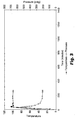
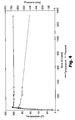
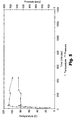
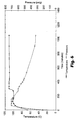
- the two-part catalysts of the present invention produce a relatively rapid drop in reactor pressure over time (from conversion of gaseous TFE and-SO 2 F 2 reagents to liquid products), whereas the comparative one-part metal fluoride catalysts produce a much slower drop in reactor pressure at comparable or higher temperatures.
- the rate of pressure drop in these examples is a direct measure of the rate of reaction of TFE with SO 2 F 2 to produce PESF and/or PDES.
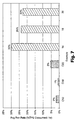
- the relatively high activity of the two-part catalysts of the present invention compared to known one-part metal fluoride catalysts is also apparent from the bar graph in Figure 7 showing average rates of TFE conversion. The latter rates were calculated by taking the percent TFE conversion measured at the end of the reaction and dividing by the total reaction time in hours.
- the catalytic reaction of the present invention was run in two different modes.
- the "pre-charge” mode was used for Examples 27-28 and the “co-feed” mode was used for the Examples 29-46. These Examples were organized into five series where each series was run with one batch of solvent/catalyst mixture.
- a 1-gallon (3.8 liter) volume, stirred tank reactor with a 400-psig-(2.86 MPa) rupture disk setting and a connection to a 375-psi (2.59 MPa) nitrogen supply and a vacuum was used.
- the reactor had a water jacket for temperature control.
- a controller was used to operate a steam-water ratio valve to control the jacket temperature.
- TFE was supplied through a carbon absorption column to remove the limonene inhibitor.
- the reactor was evacuated to evaporate as much water as possible. After the rinse and boil-out procedure was completed, the reactor was charged with the next solvent/catalyst mixture from a 2.25 liter stainless steel cylinder. After the completion of a series, the reactor was drained, cleaned out as before, and then charged with the next batch of solvent/catalyst.
- KF (anhyd) 1.845 Kg FC43 4 2 0.944 Kg DMF, 62.5 g. 18-crown-6 (anhyd), 31.2 g. KF (anhyd), 1.773 Kg FC3255 5 3 1.888 Kg DMF, 62.5 g. 18-crown-6 (anhyd), 31.2 g. KF (anhyd)
- the first two catalytic reactions were carried out in the precharge mode.
- the reactor was heated to the run temperature and then charged with all the SO 2 F 2 used in the reaction.
- TFE was charged to raise the pressure to the desired run pressure and the reaction was started.
- the pressure dropped as reactants were consumed.
- the pressure dropped by 10 psi (69 kPa) more TFE was fed to the reactor to bring the pressure back to the target run pressure.
- the TFE feed was stopped and the reactor pressure was allowed to drop as the reaction went to completion.
- the initially evacuated, preheated reactor was first charged to approximately half the desired run pressure with SO 2 F 2 , and then TFE was added to bring the pressure up to the run pressure, usually 240 psia (1.65 MPa).
- SO 2 F 2 and TFE were alternately added to maintain the reactor pressure at the desired run pressure until the total feed of reactants for that run had been reached. Because the two feed gases had differing solubilities in the solvent/catalyst mixture, SO 2 F 2 was usually added in about 10 psi (69 KPa) intervals, and TFE was usually added in about 13 psi (90 kPa) intervals. When all SO 2 F 2 and TFE for a run had been added, the pressure was allowed to run down until the reaction reached completion.
- Samples were analyzed on an HP 5890 Gas Chromatograph equipped with a packed 9'X 1/8" (275 cm x .32 cm) stainless steel Supelco 60/80 Carbopack C column, and a thermal conductivity detector. The oven was ramped from 0 to 250°C at 15°C per minute with no initial isothermal hold. Low boiling samples were analyzed by cold-injection using a 10-microliter syringe pre-chilled to dry-ice temperatures in a plastic bag to prevent frosting. Gas samples were introduced using a disposable 1 ml plastic syringe. Area percent responses by GC were assumed proportional to mass percent concentrations from the product samples.
- reaction time i.e., run time
- reaction time for Example 41 was 33 hours.
- the catalyst system may also be reused multiple times.
Landscapes
- Chemical & Material Sciences (AREA)
- Organic Chemistry (AREA)
- Organic Low-Molecular-Weight Compounds And Preparation Thereof (AREA)
- Low-Molecular Organic Synthesis Reactions Using Catalysts (AREA)
- Catalysts (AREA)
Applications Claiming Priority (3)
| Application Number | Priority Date | Filing Date | Title |
|---|---|---|---|
| US10/137,165 US6580006B1 (en) | 2002-05-02 | 2002-05-02 | Catalytic process for preparing perfluoroethanesulfonyl fluoride and/or perfluorodiethylsulfone |
| US137165 | 2002-05-02 | ||
| PCT/US2003/007886 WO2003095422A2 (en) | 2002-05-02 | 2003-03-13 | Catalytic process for preparing perfluoroethanesulfonyl fluoride and/or perfluorodiethylsulfone |
Publications (2)
| Publication Number | Publication Date |
|---|---|
| EP1501792A2 EP1501792A2 (en) | 2005-02-02 |
| EP1501792B1 true EP1501792B1 (en) | 2007-02-14 |
Family
ID=22476089
Family Applications (1)
| Application Number | Title | Priority Date | Filing Date |
|---|---|---|---|
| EP03716577A Expired - Lifetime EP1501792B1 (en) | 2002-05-02 | 2003-03-13 | Catalytic process for preparing perfluoroethanesulfonyl fluoride and/or perfluorodiethylsulfone |
Country Status (9)
| Country | Link |
|---|---|
| US (1) | US6580006B1 (enExample) |
| EP (1) | EP1501792B1 (enExample) |
| JP (1) | JP4417833B2 (enExample) |
| CN (1) | CN1290827C (enExample) |
| AT (1) | ATE353872T1 (enExample) |
| AU (1) | AU2003220279A1 (enExample) |
| DE (1) | DE60311795T2 (enExample) |
| DK (1) | DK1501792T3 (enExample) |
| WO (1) | WO2003095422A2 (enExample) |
Families Citing this family (9)
| Publication number | Priority date | Publication date | Assignee | Title |
|---|---|---|---|---|
| AU2004316117A1 (en) * | 2003-08-11 | 2005-09-01 | E.I. Dupont De Nemours And Company | Methods using fluorosulfones for extinguishing and preventing fire, |
| CA2660449A1 (en) * | 2006-08-11 | 2008-09-04 | California Institute Of Technology | Dissociating agents, formulations and methods providing enhanced solubility of fluorides |
| US8658309B2 (en) * | 2006-08-11 | 2014-02-25 | California Institute Of Technology | Dissociating agents, formulations and methods providing enhanced solubility of fluorides |
| WO2009000748A1 (en) * | 2007-06-27 | 2008-12-31 | Solvay Fluor Gmbh | Preparation of compounds with a perfluoroalkylsulfonyl group |
| WO2010053962A1 (en) * | 2008-11-04 | 2010-05-14 | California Institute Of Technology | Hybrid electrochemical generator with a soluble anode |
| CN112004651A (zh) | 2018-04-26 | 2020-11-27 | 3M创新有限公司 | 氟砜 |
| CN112041114B (zh) | 2018-05-01 | 2022-12-06 | 3M创新有限公司 | 可适形的磨料制品 |
| CN116472635A (zh) | 2020-11-03 | 2023-07-21 | 3M创新有限公司 | 电子部件浸渍冷却用流体 |
| CN114917855B (zh) * | 2022-05-25 | 2024-03-12 | 金华永和氟化工有限公司 | 一种连续制备全氟烷基乙烯基醚的反应系统及方法 |
Family Cites Families (10)
| Publication number | Priority date | Publication date | Assignee | Title |
|---|---|---|---|---|
| US2519983A (en) | 1948-11-29 | 1950-08-22 | Minnesota Mining & Mfg | Electrochemical process of making fluorine-containing carbon compounds |
| US3542864A (en) | 1966-07-13 | 1970-11-24 | Minnesota Mining & Mfg | Process for the production of perfluoroalkanesulfonyl fluorides |
| GB1189561A (en) | 1967-02-21 | 1970-04-29 | E I Du Pont De Neomours And Co | Process for Preparing Fluorinated Organic Sulfonyl Derivatives and Sulfones |
| US3920738A (en) * | 1974-03-20 | 1975-11-18 | Pennwalt Corp | Preparation of methane sulfonyl fluoride |
| US4269790A (en) * | 1978-03-23 | 1981-05-26 | Chevron Research Company | Hydrocarbylethyl sulfonyl fluoride |
| US5206440A (en) * | 1992-01-21 | 1993-04-27 | E. I. Du Pont De Nemours And Company | Oxidation of fluorine containing sulfides to sulfones |
| US5318674A (en) * | 1993-06-30 | 1994-06-07 | Minnesota Mining And Manufacturing Company | Process for preparing perfluoroalkanesulfonyl fluorides |
| DE69625336T2 (de) | 1995-02-06 | 2003-09-11 | E.I. Du Pont De Nemours And Co., Wilmington | Amorphe tetrafluoroethylen-hexafluoropropylencopolymere |
| US5780682A (en) | 1995-04-04 | 1998-07-14 | Haldor Topsoe A/S | Process for the synthesis of fluorinated alkyl sulphonyl halides |
| US6372829B1 (en) | 1999-10-06 | 2002-04-16 | 3M Innovative Properties Company | Antistatic composition |
-
2002
- 2002-05-02 US US10/137,165 patent/US6580006B1/en not_active Expired - Lifetime
-
2003
- 2003-03-13 DE DE60311795T patent/DE60311795T2/de not_active Expired - Fee Related
- 2003-03-13 AT AT03716577T patent/ATE353872T1/de not_active IP Right Cessation
- 2003-03-13 JP JP2004503443A patent/JP4417833B2/ja not_active Expired - Fee Related
- 2003-03-13 WO PCT/US2003/007886 patent/WO2003095422A2/en not_active Ceased
- 2003-03-13 EP EP03716577A patent/EP1501792B1/en not_active Expired - Lifetime
- 2003-03-13 AU AU2003220279A patent/AU2003220279A1/en not_active Abandoned
- 2003-03-13 DK DK03716577T patent/DK1501792T3/da active
- 2003-03-13 CN CNB03809990XA patent/CN1290827C/zh not_active Expired - Fee Related
Also Published As
| Publication number | Publication date |
|---|---|
| JP2005524718A (ja) | 2005-08-18 |
| WO2003095422A3 (en) | 2004-04-08 |
| CN1290827C (zh) | 2006-12-20 |
| ATE353872T1 (de) | 2007-03-15 |
| CN1649835A (zh) | 2005-08-03 |
| DE60311795D1 (de) | 2007-03-29 |
| DK1501792T3 (da) | 2007-06-04 |
| JP4417833B2 (ja) | 2010-02-17 |
| DE60311795T2 (de) | 2007-12-06 |
| AU2003220279A1 (en) | 2003-11-11 |
| EP1501792A2 (en) | 2005-02-02 |
| WO2003095422A2 (en) | 2003-11-20 |
| US6580006B1 (en) | 2003-06-17 |
Similar Documents
| Publication | Publication Date | Title |
|---|---|---|
| JP5093972B2 (ja) | フルオロオレフィンの製造方法 | |
| US4311863A (en) | Process for the manufacture of 1,1,1,2-tetrafluoroethane | |
| KR101676054B1 (ko) | 폴리(펜타플루오로설파닐)방향족 화합물을 제조하기 위한 공정 | |
| EP1501792B1 (en) | Catalytic process for preparing perfluoroethanesulfonyl fluoride and/or perfluorodiethylsulfone | |
| CN103347842B (zh) | 部分氟化的亚磺酸单体和它们的盐 | |
| JP2002003469A (ja) | 非プロトン性溶媒中での過酸化ジアシルの合成 | |
| JP2776942B2 (ja) | 対応するフルオロオキシ―フルオロスルホニル―フルオロ化合物を製造するためのフルオロ―β―スルトンの直接フッ素化 | |
| JP2022070145A (ja) | 含フッ素カルボン酸塩の製造方法 | |
| EP2238123B1 (en) | Addition reaction to fluoroallylfluorosulfate | |
| Smart | Perfluoromethylenecyclopropane and 1-trifluoromethyl-2, 3, 3-trifluorocyclopropene | |
| JP2004269535A (ja) | (ペル)フルオロハロゲンエーテルの製造方法 | |
| JPH013140A (ja) | フルオロジビニルエ−テル化合物及びその製造方法 | |
| JPH0637416B2 (ja) | フルオロジビニルエ−テル化合物及びその製造方法 | |
| US6191326B1 (en) | Process for preparing 1,1,1,2,3,3,3-heptafluoropropane | |
| JP4804762B2 (ja) | フルオロハロゲンエーテルの製造方法 | |
| JP2001335560A (ja) | 二酸化炭素中での過酸化ジアシルの合成 | |
| KR101125167B1 (ko) | 플루오로할로겐에테르 제조방법 | |
| US7375253B2 (en) | Process for the preparation of (per)fluorinated mono-functional carbonyl compounds | |
| JP2916602B2 (ja) | フッ素含有エーテル化合物の製造方法 | |
| JP4231999B2 (ja) | ω−ヨウ化含フッ素アルキルビニルエーテルの製造方法 | |
| JP2589050B2 (ja) | ペンタフルオロエチル−2,2−ジフルオロエチルエーテル及びその製造方法 | |
| JP2589959B2 (ja) | ペンタフルオロエチルフルオロプロピルエーテル類及びその製造方法 | |
| JP2020011926A (ja) | ハロゲン化エーテル類の製造方法 | |
| JPH11181022A (ja) | 含フルオロエチレン樹脂の製造方法 | |
| JP2796612B2 (ja) | 含フッ素エ−テル化合物及びその製造方法 |
Legal Events
| Date | Code | Title | Description |
|---|---|---|---|
| PUAI | Public reference made under article 153(3) epc to a published international application that has entered the european phase |
Free format text: ORIGINAL CODE: 0009012 |
|
| 17P | Request for examination filed |
Effective date: 20041125 |
|
| AK | Designated contracting states |
Kind code of ref document: A2 Designated state(s): AT BE BG CH CY CZ DE DK EE ES FI FR GB GR HU IE IT LI LU MC NL PT RO SE SI SK TR |
|
| AX | Request for extension of the european patent |
Extension state: AL LT LV MK |
|
| GRAP | Despatch of communication of intention to grant a patent |
Free format text: ORIGINAL CODE: EPIDOSNIGR1 |
|
| GRAS | Grant fee paid |
Free format text: ORIGINAL CODE: EPIDOSNIGR3 |
|
| GRAA | (expected) grant |
Free format text: ORIGINAL CODE: 0009210 |
|
| AK | Designated contracting states |
Kind code of ref document: B1 Designated state(s): AT BE BG CH CY CZ DE DK EE ES FI FR GB GR HU IE IT LI LU MC NL PT RO SE SI SK TR |
|
| PG25 | Lapsed in a contracting state [announced via postgrant information from national office to epo] |
Ref country code: NL Free format text: LAPSE BECAUSE OF FAILURE TO SUBMIT A TRANSLATION OF THE DESCRIPTION OR TO PAY THE FEE WITHIN THE PRESCRIBED TIME-LIMIT Effective date: 20070214 Ref country code: BE Free format text: LAPSE BECAUSE OF FAILURE TO SUBMIT A TRANSLATION OF THE DESCRIPTION OR TO PAY THE FEE WITHIN THE PRESCRIBED TIME-LIMIT Effective date: 20070214 Ref country code: CH Free format text: LAPSE BECAUSE OF FAILURE TO SUBMIT A TRANSLATION OF THE DESCRIPTION OR TO PAY THE FEE WITHIN THE PRESCRIBED TIME-LIMIT Effective date: 20070214 Ref country code: SI Free format text: LAPSE BECAUSE OF FAILURE TO SUBMIT A TRANSLATION OF THE DESCRIPTION OR TO PAY THE FEE WITHIN THE PRESCRIBED TIME-LIMIT Effective date: 20070214 Ref country code: FI Free format text: LAPSE BECAUSE OF FAILURE TO SUBMIT A TRANSLATION OF THE DESCRIPTION OR TO PAY THE FEE WITHIN THE PRESCRIBED TIME-LIMIT Effective date: 20070214 Ref country code: AT Free format text: LAPSE BECAUSE OF FAILURE TO SUBMIT A TRANSLATION OF THE DESCRIPTION OR TO PAY THE FEE WITHIN THE PRESCRIBED TIME-LIMIT Effective date: 20070214 Ref country code: LI Free format text: LAPSE BECAUSE OF FAILURE TO SUBMIT A TRANSLATION OF THE DESCRIPTION OR TO PAY THE FEE WITHIN THE PRESCRIBED TIME-LIMIT Effective date: 20070214 |
|
| REG | Reference to a national code |
Ref country code: GB Ref legal event code: FG4D |
|
| REG | Reference to a national code |
Ref country code: CH Ref legal event code: EP |
|
| PGFP | Annual fee paid to national office [announced via postgrant information from national office to epo] |
Ref country code: DK Payment date: 20070329 Year of fee payment: 5 |
|
| REF | Corresponds to: |
Ref document number: 60311795 Country of ref document: DE Date of ref document: 20070329 Kind code of ref document: P |
|
| REG | Reference to a national code |
Ref country code: IE Ref legal event code: FG4D |
|
| PG25 | Lapsed in a contracting state [announced via postgrant information from national office to epo] |
Ref country code: SE Free format text: LAPSE BECAUSE OF FAILURE TO SUBMIT A TRANSLATION OF THE DESCRIPTION OR TO PAY THE FEE WITHIN THE PRESCRIBED TIME-LIMIT Effective date: 20070514 |
|
| PG25 | Lapsed in a contracting state [announced via postgrant information from national office to epo] |
Ref country code: BG Free format text: LAPSE BECAUSE OF EXPIRATION OF PROTECTION Effective date: 20070515 |
|
| PG25 | Lapsed in a contracting state [announced via postgrant information from national office to epo] |
Ref country code: ES Free format text: LAPSE BECAUSE OF FAILURE TO SUBMIT A TRANSLATION OF THE DESCRIPTION OR TO PAY THE FEE WITHIN THE PRESCRIBED TIME-LIMIT Effective date: 20070525 |
|
| PG25 | Lapsed in a contracting state [announced via postgrant information from national office to epo] |
Ref country code: PT Free format text: LAPSE BECAUSE OF FAILURE TO SUBMIT A TRANSLATION OF THE DESCRIPTION OR TO PAY THE FEE WITHIN THE PRESCRIBED TIME-LIMIT Effective date: 20070716 |
|
| NLV1 | Nl: lapsed or annulled due to failure to fulfill the requirements of art. 29p and 29m of the patents act | ||
| ET | Fr: translation filed | ||
| REG | Reference to a national code |
Ref country code: CH Ref legal event code: PL |
|
| PG25 | Lapsed in a contracting state [announced via postgrant information from national office to epo] |
Ref country code: SK Free format text: LAPSE BECAUSE OF FAILURE TO SUBMIT A TRANSLATION OF THE DESCRIPTION OR TO PAY THE FEE WITHIN THE PRESCRIBED TIME-LIMIT Effective date: 20070214 |
|
| PLBE | No opposition filed within time limit |
Free format text: ORIGINAL CODE: 0009261 |
|
| STAA | Information on the status of an ep patent application or granted ep patent |
Free format text: STATUS: NO OPPOSITION FILED WITHIN TIME LIMIT |
|
| PG25 | Lapsed in a contracting state [announced via postgrant information from national office to epo] |
Ref country code: CZ Free format text: LAPSE BECAUSE OF FAILURE TO SUBMIT A TRANSLATION OF THE DESCRIPTION OR TO PAY THE FEE WITHIN THE PRESCRIBED TIME-LIMIT Effective date: 20070214 Ref country code: RO Free format text: LAPSE BECAUSE OF FAILURE TO SUBMIT A TRANSLATION OF THE DESCRIPTION OR TO PAY THE FEE WITHIN THE PRESCRIBED TIME-LIMIT Effective date: 20070214 |
|
| 26N | No opposition filed |
Effective date: 20071115 |
|
| PG25 | Lapsed in a contracting state [announced via postgrant information from national office to epo] |
Ref country code: MC Free format text: LAPSE BECAUSE OF NON-PAYMENT OF DUE FEES Effective date: 20070331 Ref country code: IE Free format text: LAPSE BECAUSE OF NON-PAYMENT OF DUE FEES Effective date: 20070313 |
|
| PG25 | Lapsed in a contracting state [announced via postgrant information from national office to epo] |
Ref country code: GR Free format text: LAPSE BECAUSE OF FAILURE TO SUBMIT A TRANSLATION OF THE DESCRIPTION OR TO PAY THE FEE WITHIN THE PRESCRIBED TIME-LIMIT Effective date: 20070515 |
|
| PGFP | Annual fee paid to national office [announced via postgrant information from national office to epo] |
Ref country code: GB Payment date: 20080327 Year of fee payment: 6 Ref country code: IT Payment date: 20080326 Year of fee payment: 6 |
|
| PGFP | Annual fee paid to national office [announced via postgrant information from national office to epo] |
Ref country code: DE Payment date: 20080430 Year of fee payment: 6 Ref country code: FR Payment date: 20080317 Year of fee payment: 6 |
|
| REG | Reference to a national code |
Ref country code: DK Ref legal event code: EBP |
|
| PG25 | Lapsed in a contracting state [announced via postgrant information from national office to epo] |
Ref country code: EE Free format text: LAPSE BECAUSE OF FAILURE TO SUBMIT A TRANSLATION OF THE DESCRIPTION OR TO PAY THE FEE WITHIN THE PRESCRIBED TIME-LIMIT Effective date: 20070214 |
|
| PG25 | Lapsed in a contracting state [announced via postgrant information from national office to epo] |
Ref country code: DK Free format text: LAPSE BECAUSE OF NON-PAYMENT OF DUE FEES Effective date: 20080331 |
|
| PG25 | Lapsed in a contracting state [announced via postgrant information from national office to epo] |
Ref country code: CY Free format text: LAPSE BECAUSE OF FAILURE TO SUBMIT A TRANSLATION OF THE DESCRIPTION OR TO PAY THE FEE WITHIN THE PRESCRIBED TIME-LIMIT Effective date: 20070214 |
|
| PG25 | Lapsed in a contracting state [announced via postgrant information from national office to epo] |
Ref country code: LU Free format text: LAPSE BECAUSE OF NON-PAYMENT OF DUE FEES Effective date: 20070313 |
|
| PG25 | Lapsed in a contracting state [announced via postgrant information from national office to epo] |
Ref country code: HU Free format text: LAPSE BECAUSE OF FAILURE TO SUBMIT A TRANSLATION OF THE DESCRIPTION OR TO PAY THE FEE WITHIN THE PRESCRIBED TIME-LIMIT Effective date: 20070815 Ref country code: TR Free format text: LAPSE BECAUSE OF FAILURE TO SUBMIT A TRANSLATION OF THE DESCRIPTION OR TO PAY THE FEE WITHIN THE PRESCRIBED TIME-LIMIT Effective date: 20070214 |
|
| GBPC | Gb: european patent ceased through non-payment of renewal fee |
Effective date: 20090313 |
|
| REG | Reference to a national code |
Ref country code: FR Ref legal event code: ST Effective date: 20091130 |
|
| PG25 | Lapsed in a contracting state [announced via postgrant information from national office to epo] |
Ref country code: DE Free format text: LAPSE BECAUSE OF NON-PAYMENT OF DUE FEES Effective date: 20091001 |
|
| PG25 | Lapsed in a contracting state [announced via postgrant information from national office to epo] |
Ref country code: FR Free format text: LAPSE BECAUSE OF NON-PAYMENT OF DUE FEES Effective date: 20091123 Ref country code: GB Free format text: LAPSE BECAUSE OF NON-PAYMENT OF DUE FEES Effective date: 20090313 |
|
| PG25 | Lapsed in a contracting state [announced via postgrant information from national office to epo] |
Ref country code: IT Free format text: LAPSE BECAUSE OF NON-PAYMENT OF DUE FEES Effective date: 20090313 |