EP1500747A1 - Supported energy absorbing structure - Google Patents
Supported energy absorbing structure Download PDFInfo
- Publication number
- EP1500747A1 EP1500747A1 EP04017509A EP04017509A EP1500747A1 EP 1500747 A1 EP1500747 A1 EP 1500747A1 EP 04017509 A EP04017509 A EP 04017509A EP 04017509 A EP04017509 A EP 04017509A EP 1500747 A1 EP1500747 A1 EP 1500747A1
- Authority
- EP
- European Patent Office
- Prior art keywords
- energy absorbing
- elements
- avalanches
- supportive
- felling
- Prior art date
- Legal status (The legal status is an assumption and is not a legal conclusion. Google has not performed a legal analysis and makes no representation as to the accuracy of the status listed.)
- Granted
Links
Images

Classifications
-
- E—FIXED CONSTRUCTIONS
- E01—CONSTRUCTION OF ROADS, RAILWAYS, OR BRIDGES
- E01F—ADDITIONAL WORK, SUCH AS EQUIPPING ROADS OR THE CONSTRUCTION OF PLATFORMS, HELICOPTER LANDING STAGES, SIGNS, SNOW FENCES, OR THE LIKE
- E01F7/00—Devices affording protection against snow, sand drifts, side-wind effects, snowslides, avalanches or falling rocks; Anti-dazzle arrangements ; Sight-screens for roads, e.g. to mask accident site
- E01F7/04—Devices affording protection against snowslides, avalanches or falling rocks, e.g. avalanche preventing structures, galleries
- E01F7/045—Devices specially adapted for protecting against falling rocks, e.g. galleries, nets, rock traps
Definitions
- the invention relates to a supporting Energy absorbing structure for flexible protective structures against Rockfall, felling, avalanches or the like after the Preamble of claim 1.
- the invention particularly relates to a supporting Energy absorbing structure for flexible protective structures against falling rocks, felling, avalanches or the like, the integrated directly into the interception structure of the protective barrier is, so much of the energy input, introduced by a falling, rolling or jumping Rock body or the like already by the combination Capture structure and supporting energy absorbing structure can be reduced.
- the invention preferably provides that in addition Connecting elements such as steel cables or the like via an entire field length or multiple fields up to the total length of the protective barrier construction in certain Distances to the carrying ropes (edge ropes) approximately parallel to be integrated into the interception structure.
- the fasteners either directly with the used Interception structure (for example: ring network, omega network or the like) and / or associated with their braid.
- These Connection can be made via conventional fasteners, such as For example: terminals, shackles or the like are generated, or
- the fasteners may be connected to the interception structure (e.g. Ring network, omega network or the like) and / or their Braid pad sewn or looped.
- middle ropes The number of fasteners used, called in a further consequence middle ropes, and their distance from the support cables is the Schutzverbauung used, or adapt their energy intake class. If the middle ropes are guided over only one field of the protective structure, they are fastened either directly to elements of the support structure in combination with energy absorbing elements or guided on the support structure via guide elements (eg: shackle, guide saddle or the like), which in turn can be supported by energy absorbing elements and directly in combination with energy absorbing elements connected to the ground (by means of rock anchors or the like).
- guide elements eg: shackle, guide saddle or the like
- Fig. 1 shows the side view of a first embodiment a protective barrier against stone chipping, felling, avalanches or similar.
- the Schutzverbauung has a support structure 1, the is shown schematically by a dashed line. It is in the example case by an upper suspension cable 2 and a lower support cable 3 with the elements of a support structure 10th connected.
- the interception structure 1 preferably has coarse-meshed Network elements 1 (e.g., ring network, omega network, etc.) on, the partially by applying Malawimaschiger Braided pads are supported to penetrate to prevent small impact body.
- coarse-meshed Network elements 1 e.g., ring network, omega network, etc.
- the task of Intercepting structure 1 is, as the name suggests, in the interception the impactor. By plastic deformation of the Mesh elements become part of the impact body introduced kinetic energy degraded.
- the interception structure 1 is achieved by means of a connection structure connected to the support structure.
- the connection structure points one (or more) upper suspension cable (s) 2 and one (or more) Lower suspension rope (s) 3, also called edge ropes, of Column head to Column head (or from Column foot to Column foot) be stretched over one (or more) system field (s).
- the Supporting cables 2, 3 are either attached to elements of the support structure or by rock anchor 9 attached to the ground. They stretch with the support structure on the interception structure.
- connection structure Other elements of the connection structure are restraint ropes 6, the head sides of the support structure elements (e.g. a version as pendulum supports) on the mountain side with the Substrate by means of anchoring (eg rock anchor) 9 connect and hold in a statically determined position.
- anchoring eg rock anchor
- connection structure suspension cables 2,3 and Restraining ropes 6
- the components of the connection structure are preferably by energy absorbing elements 8 supported.
- the leadership of the Carrying ropes "braked” executed that is, that the Connection of the suspension cables with the support structure or their Guiding on the support structure by means of energy absorbing elements is performed.
- Energyabsorbtechniksetti is about plastic and / or elastic deformation or by friction, a majority of Entry energy dissipated.
- the support structure has carriers 10 whose length (Installation height) and their horizontal distance (field lengths) from expected energy input can be determined. In general are Field lengths of about 10 m usual.
- the storage of the carrier 10 is preferably carried out over Floor panels 5.
- the connection of the carrier 10 to the Floor panels 5 is done either via a pendulum joint (Pendulum support) or as a fixed connection (welded, screwed or the like).
- the bottom plate 5 becomes with the underground directly over Felsanker or the like connected or floating and with Retaining ropes withheld on the mountain side.
- the head portion of the carrier 10 with Retaining ropes 6 retained on the mountain side and so in static held certain position.
- the energy absorbing elements 8 are preferably closely related to the Connection structure used. They are combined with the retaining ropes 6, 2.3 supporting cables and / or their leadership installed in the area of the supporting structure. It is also possible To provide energy absorbing elements, which via a Connecting structure (for example: steel cables) punctually with the Interception structure are connected. This will be the Trap structure by energy absorbing elements directly supported.
- a Connecting structure for example: steel cables
- the supports 10 of the support structure are referred to Base plates 5, preferably via a pendulum joint stored.
- the bottom plates 5 are with rock anchors 9 on the ground attached.
- the carrier 10 are with retaining ropes 6 am Head restrained on the mountain side and so in position held.
- the retaining ropes 6 are in the range of their Anchoring 9 by energy absorbing elements 8 supported.
- the Verbausystem shown is in the illustrated Embodiment with two middle ropes 7 in different Height equipped. These cables 7 are in the illustrated case with the interception structure 1 over its entire length (except in Area of the carrier 10 connected. In the area of the carrier or the support structure 10, the ropes by cable guides (here shackles) led, laterally they are through Energy absorbing elements 8 supported and with rock anchors 9 attached to the ground.
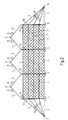
- Fig. 2 is a second embodiment of shown energy absorbing structure according to the invention, in which all parts of the embodiment according to the Fig. 1 correspond to the same reference numerals Marked are. Accordingly, on the previous versions.
- the interception structure 1 before assembly folded on one or more of the carrier 10th can be arranged.
Landscapes
- Engineering & Computer Science (AREA)
- Architecture (AREA)
- Civil Engineering (AREA)
- Structural Engineering (AREA)
- Devices Affording Protection Of Roads Or Walls For Sound Insulation (AREA)
- Buildings Adapted To Withstand Abnormal External Influences (AREA)
Abstract
Description
Die Erfindung betrifft eine unterstützende Energieabsorbierungsstruktur für flexible Schutzbauten gegen Steinschlag, Holzschlag, Lawinen oder Ähnliches nach dem Oberbegriff des Anspruches 1.The invention relates to a supporting Energy absorbing structure for flexible protective structures against Rockfall, felling, avalanches or the like after the Preamble of claim 1.
Eine derartige Energieabsorbierungsstruktur ist aus der EP-A 484 563 bekannt.Such an energy absorbing structure is known from EP-A 484 563 known.
Gegenüber dieser bekannten Energieabsorbierungsstruktur ist es technische Aufgabe der vorliegenden Erfindung, einen effizienten Energieabbau von Schutzverbauungen gegen Steinschlag, Holzschlag, Lawinen oder Ähnliches zu erreichen, wobei es möglich sein soll, kleinere Systemgesamtverformungen und eine geringere Dimensionierung von Elementen der Abfang-, Verbindungs- und Stützstruktur sowie deren Verankerung mit dem Untergrund zu erreichen.It is opposite to this known energy absorbing structure Technical object of the present invention, a efficient energy reduction of protective barriers against To reach rockfall, felling, avalanches, or the like, where possible, smaller overall system deformations and a smaller dimensioning of elements of the intercept, Connection and support structure and their anchoring with the To reach underground.
Die Lösung dieser Aufgabe erfolgt durch die Merkmale des Anspruches 1.The solution to this problem is provided by the features of Claim 1.
Hierdurch wird u.a. erreicht, dass die Abfangstruktur nach Montage der Stützstruktur vorhangähnlich auf- und zugezogen werden kann, was die Montage der Gesamtanordnung erheblich vereinfacht.This will u.a. achieved that the interception structure after Assembly of the support structure like a curtain and pulled up can be, what the assembly of the overall arrangement considerably simplified.
Die Erfindung betrifft insbesondere eine unterstützende Energieabsorbierungsstruktur für flexible Schutzverbauungen gegen Steinschlag, Holzschlag, Lawinen oder ähnlichem, die direkt in die Abfangstruktur der Schutzverbauung integriert wird, sodass ein Großteil des Energieeintrags, eingebracht durch einen fallenden, rollenden oder springenden Gesteinskörper oder ähnlichem bereits durch die Kombination Abfangstruktur und unterstützende Energieabsorbierungsstruktur abgebaut werden kann.The invention particularly relates to a supporting Energy absorbing structure for flexible protective structures against falling rocks, felling, avalanches or the like, the integrated directly into the interception structure of the protective barrier is, so much of the energy input, introduced by a falling, rolling or jumping Rock body or the like already by the combination Capture structure and supporting energy absorbing structure can be reduced.
Die Erfindung sieht bevorzugterweise vor, dass dazu Verbindungselemente, wie etwa Stahlseile oder Ähnliches über eine gesamte Feldlänge bzw. mehrere Felder bis hin zur gesamten Verbaulänge der Schutzverbauung in bestimmten Abständen zu den Tragseilen (Randseilen) in etwa parallel zu diesen in die Abfangstruktur integriert werden. Dazu werden die Verbindungselemente entweder direkt mit der verwendeten Abfangstruktur (z.B.: Ringnetz, Omega- Netz oder ähnlichem) und/oder mit deren Geflechtsauflage verbunden. Diese Verbindung kann über herkömmliche Verbindungselemente, wie z.B.: Klemmen, Schäkel oder ähnlichem erzeugt werden, bzw. können die Verbindungselemente mit der Abfangstruktur (z.B.: Ringnetz, Omega- Netz oder ähnlichem) und/oder deren Geflechtsauflage vernäht oder geschlauft werden. Dabei ist es nicht nötig, sämtliche Maschen bzw. Ringelemente oder Ähnliches der Abfangstruktur in die Verbindung miteinzubeziehen. Es empfiehlt sich jedoch, eine über die gesamte Feldlänge bzw. Verbaulänge konstante Verbindung der Abfangstruktur und/oder deren Geflechtsauflage mit den verwendeten Verbindungselementen zu gestalten, ohne größere Bereiche der Abfangstruktur von dieser Verbindung auszuschließen. Lediglich bei Führung der Verbindungselemente über Elemente der Stützstruktur empfiehlt es sich, die Verbindung der unterstützenden Energieabsorbierungsstruktur im Bereich der Stützstruktur mit der Abfangstruktur für einen kleinen Bereich nicht auszuführen, um die Bewegungsfreiheit der Abfangstruktur nicht zu beeinträchtigen.The invention preferably provides that in addition Connecting elements such as steel cables or the like via an entire field length or multiple fields up to the total length of the protective barrier construction in certain Distances to the carrying ropes (edge ropes) approximately parallel to be integrated into the interception structure. To do this the fasteners either directly with the used Interception structure (for example: ring network, omega network or the like) and / or associated with their braid. These Connection can be made via conventional fasteners, such as For example: terminals, shackles or the like are generated, or For example, the fasteners may be connected to the interception structure (e.g. Ring network, omega network or the like) and / or their Braid pad sewn or looped. That's it not necessary, all stitches or ring elements or Similar to the scavenging structure in the compound involve. It is recommended, however, one over the entire field length or installation length constant connection of the Abfangstruktur and / or their braid with the used fasteners without larger Regions of the scaffold of this compound excluded. Only when guiding the fasteners it is recommended to use the elements of the support structure Connection of the supporting energy absorbing structure in the Area of the support structure with the interception structure for a small area does not perform to freedom of movement the capture structure is not affected.
Die Anzahl der verwendeten Verbindungselemente, in weitere
Folge Mittelseile genannt, und deren Abstand zu den Tragseilen
ist der verwendeten Schutzverbauung, bzw. deren
Energieaufnahmeklasse anzupassen.
Werden die Mittelsseile nur über ein Feld der Schutzverbauung
geführt, werden selbige entweder in Kombination mit
Energieabsorbierungselementen direkt an Elementen der
Stützstruktur befestigt oder über Führungselemente (z.B.:
Schäkel, Führungssattel oder ähnlichem), die wiederum durch
Energieabsorbierungselemente unterstützt ausgeführt werden
können, an der Stützstruktur geführt und direkt in Kombination
mit Energieabsorbierungselementen mit dem Untergrund (mittels
Felsanker oder ähnlichem) verbunden.The number of fasteners used, called in a further consequence middle ropes, and their distance from the support cables is the Schutzverbauung used, or adapt their energy intake class.
If the middle ropes are guided over only one field of the protective structure, they are fastened either directly to elements of the support structure in combination with energy absorbing elements or guided on the support structure via guide elements (eg: shackle, guide saddle or the like), which in turn can be supported by energy absorbing elements and directly in combination with energy absorbing elements connected to the ground (by means of rock anchors or the like).
Bei einer Mittelseilführung über mehrere Felder, werden die Mittelseile über Führungselemente (z.B.: Schäkel, Führungssattel oder ähnlichem), die ebenfalls mit Energieabsorbierungselementen ausgestattet sein können, an der Stützstruktur ins benachbarte Feld geführt und dort wiederum mit der Abfangstruktur in oben angeführter Weise verbunden. Die abschließende Befestigung der Mittelseile erfolgt wie beim Einbau selbiger über jeweils nur eine Feldlänge. Bei einer Mittelseilführung über mehrere Felder kann aber auch auf eine Führung der Mittelseile im Bereich einzelner Träger der Stützstruktur verzichtet werden, sodass z.B. ein Mittelseil ohne Zwischenführung über Elemente der Stützstruktur über zwei oder mehr Feldlängen mit der Abfangstruktur verbunden ist.In a Mittelseilführung over several fields, the Middle ropes over guide elements (for example: shackles, Guide saddle or the like), which also with Energieabsorbierungselementen may be equipped at the Support structure led into the neighboring field and there again connected to the interception structure in the manner mentioned above. The final attachment of the middle ropes takes place as in Installation same over each only one field length. At a Mittelseilführung over several fields but can also on a Guiding the middle ropes in the area of individual carriers of the Support structure are omitted, so that e.g. a middle rope without intermediate guidance over elements of the support structure over two or more field lengths associated with the interception structure.
Die Erfindung zeichnet sich insbesondere durch folgende
Vorteile aus:
Die Unteransprüche haben vorteilhafte Weiterbildungen der Erfindung zum Inhalt.The dependent claims have advantageous developments of Invention to the content.
Weitere Einzelheiten, Merkmale und Vorteile der Erfindung ergeben sich aus nachfolgender Beschreibung von Ausführungsbeispielen anhand der Zeichnung. Es zeigt:
- Fig. 1
- eine Seitenansicht einer ersten Ausführungsform der erfindungsgemäßen Energieabsorbierungsstruktur, und
- Fig. 2
- eine schematisch stark vereinfachte Frontansicht einer zweiten Ausführungsform der erfindungsgemäßen Energieabsorbierungsstruktur.
- Fig. 1
- a side view of a first embodiment of the energy absorbing structure according to the invention, and
- Fig. 2
- a schematically greatly simplified front view of a second embodiment of the energy absorbing structure according to the invention.
Fig. 1 zeigt die Seitenansicht einer ersten Ausführungsform
einer Schutzverbauung gegen Steinschlag, Holzschlag, Lawinen
oder Ähnliches. Die
Schutzverbauung weist eine Abfangstruktur 1 auf, die
schematisch durch ein strichpunktierte Linie dargestellt ist.
Sie wird im Beispielsfalle durch ein oberes Tragseil 2 und ein
unteres Tragseil 3 mit den Elementen einer Stützstruktur 10
verbunden.Fig. 1 shows the side view of a first embodiment
a protective barrier against stone chipping, felling, avalanches
or similar. The
Schutzverbauung has a support structure 1, the
is shown schematically by a dashed line.
It is in the example case by an upper suspension cable 2 and a
Üblicherweise gliedert sich der modulartige Aufbau solcher Schutzsysteme in eine Abfangstruktur, eine Verbindungsstruktur, eine Stützstruktur, deren Verankerung und, wenn nötig eine Fundamentierung.Usually, the modular structure of such Protection systems in a capture structure, a Connecting structure, a supporting structure, its anchoring and, if necessary, a foundation.
Die Abfangstruktur 1 weist vorzugsweise grobmaschige Netzelemente 1 (z.B.: Ringnetz, Omega- Netz, etc.) auf, die teilweise durch das Aufbringen kleinmaschiger Geflechtsauflagen unterstützt werden, um ein Durchdringen kleiner Einschlagkörper zu verhindern. Die Aufgabe der Abfangstruktur 1 besteht, wie der Name schon sagt, im Abfangen der Einschlagkörper. Durch plastische Verformung der Netzelemente wird ein Teil der durch den Einschlagkörper eingebrachten kinetischen Energie abgebaut.The interception structure 1 preferably has coarse-meshed Network elements 1 (e.g., ring network, omega network, etc.) on, the partially by applying kleinmaschiger Braided pads are supported to penetrate to prevent small impact body. The task of Intercepting structure 1 is, as the name suggests, in the interception the impactor. By plastic deformation of the Mesh elements become part of the impact body introduced kinetic energy degraded.
Die Abfangstruktur 1 wird mittels einer Verbindungsstruktur
mit der Stützstruktur verbunden. Die Verbindungsstruktur weist
ein (oder mehrere) oberes Tragseil(e) 2 und ein (oder mehrere)
unteres Tragseil(e) 3, auch Randseile genannt, die von
Stützenkopf zu Stützenkopf (bzw. von Stützenfuß zu Stützenfuß)
über ein (oder mehrere) Systemfeld(er) gespannt werden. Die
Tragseile 2,3 werden entweder an Elementen der Stützstruktur
oder durch Felsanker 9 am Untergrund befestigt. Sie spannen
mit der Stützstruktur die Abfangstruktur auf.The interception structure 1 is achieved by means of a connection structure
connected to the support structure. The connection structure points
one (or more) upper suspension cable (s) 2 and one (or more)
Lower suspension rope (s) 3, also called edge ropes, of
Column head to Column head (or from Column foot to Column foot)
be stretched over one (or more) system field (s). The
Weitere Elemente der Verbindungsstruktur sind Rückhalteseile
6, die die Kopf seiten der Stützstrukturelemente (z.B.: bei
einer Ausführung als Pendelstützen) bergseits mit dem
Untergrund mittels einer Verankerung (z.B.: Felsenanker) 9
verbinden und so in statisch bestimmter Position halten. Sind
die Hauptelemente der Stützstruktur nicht mit Felsankern oder
ähnlichem direkt mit dem Untergrund verbunden (z.B.: bei
schwimmender Lagerung), sind zudem zusätzlich im Fußbereich
der Stützelemente Rückhalteseile angebracht.Other elements of the connection structure are
Die Komponenten der Verbindungsstruktur (Tragseile 2,3 und
Rückhalteseile 6) werden vorzugsweise durch Energieabsorbierungselemente
8 unterstützt. Alternativ wird die Führung der
Tragseile "gebremst" ausgeführt, das heißt, dass die
Verbindung der Tragseile mit der Stützstruktur bzw. deren
Führung an der Stützstruktur mittels Energieabsorbierungselementen
ausgeführt wird. Durch die genannten
Energieabsorbierungselemente wird über plastische und/oder
elastische Verformung bzw. durch Reibwirkung ein Großteil der
Eintragsenergie abgebaut.The components of the connection structure (
Die Stützstruktur weist Träger 10 auf, deren Länge
(Verbauhöhe) und deren horizontaler Abstand (Feldlängen) vom
erwarteten Energieeintrag bestimmt werden. Im allgemeinen sind
Feldlängen von etwa 10 m üblich.The support structure has
Die Lagerung der Träger 10 erfolgt vorzugsweise über
Bodenplatten 5. Die Verbindung der Träger 10 zu den
Bodenplatten 5 erfolgt entweder über ein Pendelgelenk
(Pendelstütze) oder sie wird als fixe Verbindung (geschweißt,
verschraubt oder ähnlichem) hergestellt. Die Bodenplatte 5
wird mit dem Untergrund direkt über Felsanker oder ähnlichem
verbunden oder wird schwimmend gelagert und mit
Rückhalteseilen bergseits zurückgehalten. Bei einer Ausführung
als Pendelstütze wird der Kopfbereich des Trägers 10 mit
Rückhalteseilen 6 bergseits zurückgehalten und so in statisch
bestimmter Position gehalten. The storage of the
Wie schon erwähnt wird ein Großteil der Eintragsenergie durch
Energieabsorbierungselemente 8 verschiedenster Bauart und
Funktionsweise abgebaut. Die Energieabsorbierungselemente 8
werden vorzugsweise im engen Zusammenhang mit der
Verbindungsstruktur eingesetzt. Sie werden in Kombination mit
den Rückhalteseilen 6, Tragseilen 2,3 und/oder deren Führung
im Bereich der Stützstruktur eingebaut. Ferner ist es möglich,
Energieabsorbierungselemente vorzusehen, die über eine
Verbindungsstruktur (z.B.: Stahlseile) punktuell mit der
Abfangstruktur verbunden werden. Dadurch wird die
Abfangstruktur durch Energieabsorbierungselemente direkt
unterstützt.As already mentioned, a large part of the entry energy is due to
Die Träger 10 der Stützstruktur werden auf den besagten
Bodenplatten 5, vorzugsweise über ein Pendelgelenk, gelagert.
Die Bodenplatten 5 sind mit Felsankern 9 am Untergrund
befestigt. Die Träger 10 werden mit Rückhalteseilen 6 am
Kopfende bergseitig zurückgespannt und so in Position
gehalten. Die Rückhalteseile 6 sind im Bereich ihrer
Verankerung 9 durch Energieabsorbierungselementen 8
unterstützt.The supports 10 of the support structure are referred to
Das dargestellte Verbausystem ist bei der dargestellten
Ausführungsform mit zwei Mittelseilen 7 in unterschiedlicher
Höhe ausgestattet. Diese Seile 7 werden im dargestellten Fall
mit der Abfangstruktur 1 über deren gesamte Länge (außer im
Bereich der Träger 10 verbunden. Im Bereich der Träger bzw.
der Stützstruktur 10 werden die Seile durch Seilführungen
(hier Schäkel) geführt, seitlich werden sie durch
Energieabsorbierungselemente 8 unterstützt und mit Felsankern
9 mit dem Untergrund befestigt. The Verbausystem shown is in the illustrated
Embodiment with two
In Fig. 2 ist eine zweite Ausführungsform der erfindungsgemäßen Energieabsorbierungsstruktur dargestellt, bei der sämtliche Teile, die der Ausführungsform gemäß der Fig. 1 entsprechen, mit dem gleichen Bezugsziffern gekennzeichnet sind. Dementsprechend kann auf die vorangehenden Ausführungen Bezug genommen werden.In Fig. 2 is a second embodiment of shown energy absorbing structure according to the invention, in which all parts of the embodiment according to the Fig. 1 correspond to the same reference numerals Marked are. Accordingly, on the previous versions.
Bei der dargestellten zweiten Ausführungsform sind jedoch drei
Mittelseile 7', 7'', 7''' vorgesehen. Wie Fig. 2 verdeutlicht,
verlaufen diese untereinander vorzugsweise parallel zueinander
und ebenfalls parallel zum oberen Tragseil 2 bzw. unteren
Tragseil 3.However, in the illustrated second embodiment, there are three
Central ropes 7 ', 7' ', 7' '' provided. As Fig. 2 illustrates,
these are preferably parallel to one another
and also parallel to the upper support cable 2 and
Wie auch bei der Ausführungsform gemäß Fig. 1 macht diese
Ausführungsform während der Montage der Gesamtanordnung ein
vorhangartiges Aufziehen der Abfangstruktur 1 zwischen den
Trägern 10 möglich, wobei die Abfangstruktur 1 vor der Montage
zusammengefaltet an einem oder mehreren der Träger 10
angeordnet sein kann.As with the embodiment of FIG. 1 does this
Embodiment during the assembly of the overall arrangement
curtain-like mounting of the interception structure 1 between the
Claims (11)
Applications Claiming Priority (2)
| Application Number | Priority Date | Filing Date | Title |
|---|---|---|---|
| AT11662003 | 2003-07-24 | ||
| AT11662003 | 2003-07-24 |
Publications (3)
| Publication Number | Publication Date |
|---|---|
| EP1500747A1 true EP1500747A1 (en) | 2005-01-26 |
| EP1500747B1 EP1500747B1 (en) | 2010-04-21 |
| EP1500747B2 EP1500747B2 (en) | 2015-12-23 |
Family
ID=33479924
Family Applications (1)
| Application Number | Title | Priority Date | Filing Date |
|---|---|---|---|
| EP04017509.3A Expired - Lifetime EP1500747B2 (en) | 2003-07-24 | 2004-07-23 | Supported energy absorbing structure |
Country Status (4)
| Country | Link |
|---|---|
| EP (1) | EP1500747B2 (en) |
| AT (1) | ATE465301T1 (en) |
| DE (1) | DE502004011065D1 (en) |
| ES (1) | ES2345148T5 (en) |
Cited By (16)
| Publication number | Priority date | Publication date | Assignee | Title |
|---|---|---|---|---|
| AT503574B1 (en) * | 2006-02-01 | 2007-11-15 | Isofer Ag | Safety barrier, for protection against e.g. avalanches comprises net mounted on cables at front and back which are fitted with cable brakes to improve energy absorption, additional cables with cable brakes being attached to rear of net |
| EP1911884A1 (en) * | 2006-10-13 | 2008-04-16 | Trumer Schutzbauten GesmbH | Support for protection against falling rocks |
| ITTO20081005A1 (en) * | 2008-12-30 | 2010-06-30 | Torino Politecnico | INTEGRATED STRUCTURE OF PARAMASSI PROTECTION. |
| WO2011067479A1 (en) | 2009-11-27 | 2011-06-09 | Heaven Climber Invest - H.C. Invest | Stone deflector screen |
| ITTO20100163A1 (en) * | 2010-03-04 | 2011-09-05 | Incofil Srl | PARAMASSE BARRIER AND RELATIVE BEARING STRUCTURE. |
| EP2711461A1 (en) * | 2012-09-21 | 2014-03-26 | Trumer Schutzbauten GesmbH | Support for a rock fall obstruction |
| WO2014162098A1 (en) * | 2013-04-04 | 2014-10-09 | Mecanroc | Support and protection barrier for retaining a moving object |
| CN104246075A (en) * | 2011-12-22 | 2014-12-24 | 特鲁默舒茨鲍滕有限责任公司 | Protective control structure |
| DE202014102250U1 (en) * | 2014-05-14 | 2015-08-17 | Isofer Ag | Dynamic rockfall protection barrier |
| EP2993269A1 (en) * | 2014-09-04 | 2016-03-09 | Jakob AG | Assembly for the protection of slopes |
| US11015309B2 (en) * | 2017-12-12 | 2021-05-25 | Institute Of Mountain Hazards And Environment, Chinese Academy Of Sciences | Flexible barrier and designing method thereof |
| DE102020131710A1 (en) | 2020-11-30 | 2022-06-02 | Trumer Schutzbauten Ges.M.B.H | protection |
| US20230212832A1 (en) * | 2020-05-15 | 2023-07-06 | Trumer Schutzbauten Ges.M.B.H | Safety net for rockfall protection barriers |
| US20230220636A1 (en) * | 2020-05-08 | 2023-07-13 | Trumer Schutzbauten Ges.M.B.H | Rockfall barrier |
| CN116479796A (en) * | 2023-04-07 | 2023-07-25 | 成都理工大学 | Rolling stone blocking method, rolling stone blocking device and system |
| US12227912B1 (en) * | 2023-10-10 | 2025-02-18 | Railway Construction Research Institute, China Academy of Railway Science Group Co., Ltd. | Pile-net flexible cable barrier structure and construction method thereof |
Families Citing this family (1)
| Publication number | Priority date | Publication date | Assignee | Title |
|---|---|---|---|---|
| DE102011002245A1 (en) | 2011-04-21 | 2012-10-25 | Sfs Intec Holding Ag | Fastening device to a masonry |
Citations (5)
| Publication number | Priority date | Publication date | Assignee | Title |
|---|---|---|---|---|
| AT203043B (en) * | 1957-11-29 | 1959-04-25 | Josef Kaim Bau Und Sprengunter | Resilient guard |
| GB1303218A (en) * | 1971-04-30 | 1973-01-17 | ||
| EP0484563A1 (en) | 1988-10-12 | 1992-05-13 | Isofer Ag | Fence for avalanches, rockfall or felling |
| US5299781A (en) * | 1991-07-10 | 1994-04-05 | State Department Of Highways, State Of Colorado | Flex post fence |
| US5732935A (en) * | 1996-08-09 | 1998-03-31 | Codario, Jr.; Samuel C. | Golf barrier cross bracing system |
Family Cites Families (2)
| Publication number | Priority date | Publication date | Assignee | Title |
|---|---|---|---|---|
| IT1146501B (en) † | 1981-03-04 | 1986-11-12 | Roberto Oddo | ELASTIC PLASTIC BARRIER FOR THE PROTECTION OF PEOPLE AND THINGS FROM MASS IN MOVEMENT |
| DE20300821U1 (en) † | 2003-01-17 | 2003-04-10 | Fatzer Ag, Romanshorn | Shoring device for flowing water, especially for torrents |
-
2004
- 2004-07-23 AT AT04017509T patent/ATE465301T1/en active
- 2004-07-23 EP EP04017509.3A patent/EP1500747B2/en not_active Expired - Lifetime
- 2004-07-23 ES ES04017509.3T patent/ES2345148T5/en not_active Expired - Lifetime
- 2004-07-23 DE DE502004011065T patent/DE502004011065D1/en not_active Expired - Lifetime
Patent Citations (5)
| Publication number | Priority date | Publication date | Assignee | Title |
|---|---|---|---|---|
| AT203043B (en) * | 1957-11-29 | 1959-04-25 | Josef Kaim Bau Und Sprengunter | Resilient guard |
| GB1303218A (en) * | 1971-04-30 | 1973-01-17 | ||
| EP0484563A1 (en) | 1988-10-12 | 1992-05-13 | Isofer Ag | Fence for avalanches, rockfall or felling |
| US5299781A (en) * | 1991-07-10 | 1994-04-05 | State Department Of Highways, State Of Colorado | Flex post fence |
| US5732935A (en) * | 1996-08-09 | 1998-03-31 | Codario, Jr.; Samuel C. | Golf barrier cross bracing system |
Cited By (24)
| Publication number | Priority date | Publication date | Assignee | Title |
|---|---|---|---|---|
| AT503574B1 (en) * | 2006-02-01 | 2007-11-15 | Isofer Ag | Safety barrier, for protection against e.g. avalanches comprises net mounted on cables at front and back which are fitted with cable brakes to improve energy absorption, additional cables with cable brakes being attached to rear of net |
| EP1911884A1 (en) * | 2006-10-13 | 2008-04-16 | Trumer Schutzbauten GesmbH | Support for protection against falling rocks |
| ITTO20081005A1 (en) * | 2008-12-30 | 2010-06-30 | Torino Politecnico | INTEGRATED STRUCTURE OF PARAMASSI PROTECTION. |
| WO2011067479A1 (en) | 2009-11-27 | 2011-06-09 | Heaven Climber Invest - H.C. Invest | Stone deflector screen |
| ITTO20100163A1 (en) * | 2010-03-04 | 2011-09-05 | Incofil Srl | PARAMASSE BARRIER AND RELATIVE BEARING STRUCTURE. |
| CN104246075A (en) * | 2011-12-22 | 2014-12-24 | 特鲁默舒茨鲍滕有限责任公司 | Protective control structure |
| US9677231B2 (en) | 2011-12-22 | 2017-06-13 | Trumer Schutzbauten Gesmbh | Protection system |
| EP2711461A1 (en) * | 2012-09-21 | 2014-03-26 | Trumer Schutzbauten GesmbH | Support for a rock fall obstruction |
| WO2014162098A1 (en) * | 2013-04-04 | 2014-10-09 | Mecanroc | Support and protection barrier for retaining a moving object |
| FR3004199A1 (en) * | 2013-04-04 | 2014-10-10 | Mecanroc | SUPPORT AND PROTECTIVE BARRIER FOR RETENTING AN OBJECT IN MOTION |
| DE202014102250U1 (en) * | 2014-05-14 | 2015-08-17 | Isofer Ag | Dynamic rockfall protection barrier |
| WO2015173615A1 (en) | 2014-05-14 | 2015-11-19 | Pfeifer Isofer Ag | Dynamic stone chip protection barrier |
| EP3143209B1 (en) | 2014-05-14 | 2018-03-28 | Pfeifer Isofer AG | Dynamic stone chip protection barrier |
| CH710082A1 (en) * | 2014-09-04 | 2016-03-15 | Jakob Ag | Slope protection system. |
| EP2993269A1 (en) * | 2014-09-04 | 2016-03-09 | Jakob AG | Assembly for the protection of slopes |
| US11015309B2 (en) * | 2017-12-12 | 2021-05-25 | Institute Of Mountain Hazards And Environment, Chinese Academy Of Sciences | Flexible barrier and designing method thereof |
| US20230220636A1 (en) * | 2020-05-08 | 2023-07-13 | Trumer Schutzbauten Ges.M.B.H | Rockfall barrier |
| US12297612B2 (en) * | 2020-05-08 | 2025-05-13 | Trumer Schutzbauten Ges.M.B.H. | Rockfall barrier |
| US20230212832A1 (en) * | 2020-05-15 | 2023-07-06 | Trumer Schutzbauten Ges.M.B.H | Safety net for rockfall protection barriers |
| US12146282B2 (en) * | 2020-05-15 | 2024-11-19 | Trumer Schutzbauten Ges.M.B.H | Safety net for rockfall protection barriers |
| DE102020131710A1 (en) | 2020-11-30 | 2022-06-02 | Trumer Schutzbauten Ges.M.B.H | protection |
| WO2022112563A1 (en) | 2020-11-30 | 2022-06-02 | Trumer Schutzbauten Ges.M.B.H | Protective structure |
| CN116479796A (en) * | 2023-04-07 | 2023-07-25 | 成都理工大学 | Rolling stone blocking method, rolling stone blocking device and system |
| US12227912B1 (en) * | 2023-10-10 | 2025-02-18 | Railway Construction Research Institute, China Academy of Railway Science Group Co., Ltd. | Pile-net flexible cable barrier structure and construction method thereof |
Also Published As
| Publication number | Publication date |
|---|---|
| EP1500747B2 (en) | 2015-12-23 |
| ES2345148T5 (en) | 2016-03-16 |
| ES2345148T3 (en) | 2010-09-16 |
| DE502004011065D1 (en) | 2010-06-02 |
| ATE465301T1 (en) | 2010-05-15 |
| EP1500747B1 (en) | 2010-04-21 |
Similar Documents
| Publication | Publication Date | Title |
|---|---|---|
| EP1500747B2 (en) | Supported energy absorbing structure | |
| DE60319282T2 (en) | METHOD FOR ANCHORING PARALLEL WIRE CABLES | |
| US5961099A (en) | Safety net system for debris and mud slides | |
| EP1516964B1 (en) | Catch net in particular for rock fall restraining systems | |
| KR20100118577A (en) | Shock absorbing fence | |
| EP2794997B1 (en) | Protection structure | |
| CH692921A5 (en) | Wire mesh preferably as rockfall protection or for securing a Erdoberflächenschicht. | |
| DE10333113B3 (en) | Fall prevention device for protection of worker on flat roof has bearing plate with projecting post provided with fastening element for safety line at its top end | |
| CH697825B1 (en) | Collecting fence for avalanches rock or felling. | |
| EP0484563B1 (en) | Fence for avalanches, rockfall or felling | |
| DE3629935A1 (en) | FENCE | |
| CH637436A5 (en) | DEVICE FOR PROTECTION AGAINST STONE BLOCK AND AVALANCHE IN MOUNTAIN TERRAIN. | |
| WO2015019140A1 (en) | Post for a rockfall catching net and rockfall catching net | |
| DE202022102793U1 (en) | slackline system | |
| DE202014102250U1 (en) | Dynamic rockfall protection barrier | |
| DE202005006224U1 (en) | Crash dampener for use in front of barricade at traffic lanes has pre-determined number of dampener elements, which are adjustably arranged before barricade wherein crash dampener is also anchored by means of anchorage in the underground | |
| DE19525243C2 (en) | Impact absorber | |
| EP0370945A1 (en) | Steel wire rope net for the protection against falling rocks or avalanches | |
| DE1534538A1 (en) | Security fence | |
| DE1534486B1 (en) | Protective device to protect traffic routes that run along rock faces against falling rocks | |
| DE2639520B2 (en) | Cable connection protected against cable breakage in the event of extremely high sudden loads | |
| DE202014102251U1 (en) | Dynamic rockfall protection barrier | |
| EP2993269B1 (en) | Assembly for the protection of slopes | |
| EP3162960B1 (en) | Cable brake assembly | |
| EP2711461B1 (en) | Support for a rock fall obstruction |
Legal Events
| Date | Code | Title | Description |
|---|---|---|---|
| PUAI | Public reference made under article 153(3) epc to a published international application that has entered the european phase |
Free format text: ORIGINAL CODE: 0009012 |
|
| AK | Designated contracting states |
Kind code of ref document: A1 Designated state(s): AT BE BG CH CY CZ DE DK EE ES FI FR GB GR HU IE IT LI LU MC NL PL PT RO SE SI SK TR |
|
| AX | Request for extension of the european patent |
Extension state: AL HR LT LV MK |
|
| 17P | Request for examination filed |
Effective date: 20050719 |
|
| RIN1 | Information on inventor provided before grant (corrected) |
Inventor name: HEISS, CHRISTIAN Inventor name: PLONEK, THOMAS |
|
| AKX | Designation fees paid |
Designated state(s): AT BE BG CH CY CZ DE DK EE ES FI FR GB GR HU IE IT LI LU MC NL PL PT RO SE SI SK TR |
|
| AXX | Extension fees paid |
Extension state: MK Payment date: 20050719 Extension state: HR Payment date: 20050719 |
|
| 17Q | First examination report despatched |
Effective date: 20071220 |
|
| GRAP | Despatch of communication of intention to grant a patent |
Free format text: ORIGINAL CODE: EPIDOSNIGR1 |
|
| GRAS | Grant fee paid |
Free format text: ORIGINAL CODE: EPIDOSNIGR3 |
|
| GRAA | (expected) grant |
Free format text: ORIGINAL CODE: 0009210 |
|
| AK | Designated contracting states |
Kind code of ref document: B1 Designated state(s): AT BE BG CH CY CZ DE DK EE ES FI FR GB GR HU IE IT LI LU MC NL PL PT RO SE SI SK TR |
|
| AX | Request for extension of the european patent |
Extension state: HR MK |
|
| REG | Reference to a national code |
Ref country code: GB Ref legal event code: FG4D Free format text: NOT ENGLISH |
|
| REG | Reference to a national code |
Ref country code: CH Ref legal event code: EP |
|
| REG | Reference to a national code |
Ref country code: IE Ref legal event code: FG4D Free format text: LANGUAGE OF EP DOCUMENT: GERMAN |
|
| REF | Corresponds to: |
Ref document number: 502004011065 Country of ref document: DE Date of ref document: 20100602 Kind code of ref document: P |
|
| REG | Reference to a national code |
Ref country code: RO Ref legal event code: EPE |
|
| REG | Reference to a national code |
Ref country code: CH Ref legal event code: NV Representative=s name: KELLER & PARTNER PATENTANWAELTE AG WINTERTHUR |
|
| REG | Reference to a national code |
Ref country code: NL Ref legal event code: VDEP Effective date: 20100421 |
|
| REG | Reference to a national code |
Ref country code: ES Ref legal event code: FG2A Ref document number: 2345148 Country of ref document: ES Kind code of ref document: T3 |
|
| PG25 | Lapsed in a contracting state [announced via postgrant information from national office to epo] |
Ref country code: NL Free format text: LAPSE BECAUSE OF FAILURE TO SUBMIT A TRANSLATION OF THE DESCRIPTION OR TO PAY THE FEE WITHIN THE PRESCRIBED TIME-LIMIT Effective date: 20100421 Ref country code: SE Free format text: LAPSE BECAUSE OF FAILURE TO SUBMIT A TRANSLATION OF THE DESCRIPTION OR TO PAY THE FEE WITHIN THE PRESCRIBED TIME-LIMIT Effective date: 20100421 |
|
| REG | Reference to a national code |
Ref country code: IE Ref legal event code: FD4D |
|
| PG25 | Lapsed in a contracting state [announced via postgrant information from national office to epo] |
Ref country code: FI Free format text: LAPSE BECAUSE OF FAILURE TO SUBMIT A TRANSLATION OF THE DESCRIPTION OR TO PAY THE FEE WITHIN THE PRESCRIBED TIME-LIMIT Effective date: 20100421 Ref country code: SI Free format text: LAPSE BECAUSE OF FAILURE TO SUBMIT A TRANSLATION OF THE DESCRIPTION OR TO PAY THE FEE WITHIN THE PRESCRIBED TIME-LIMIT Effective date: 20100421 |
|
| PG25 | Lapsed in a contracting state [announced via postgrant information from national office to epo] |
Ref country code: GR Free format text: LAPSE BECAUSE OF FAILURE TO SUBMIT A TRANSLATION OF THE DESCRIPTION OR TO PAY THE FEE WITHIN THE PRESCRIBED TIME-LIMIT Effective date: 20100722 Ref country code: CY Free format text: LAPSE BECAUSE OF FAILURE TO SUBMIT A TRANSLATION OF THE DESCRIPTION OR TO PAY THE FEE WITHIN THE PRESCRIBED TIME-LIMIT Effective date: 20100421 Ref country code: PL Free format text: LAPSE BECAUSE OF FAILURE TO SUBMIT A TRANSLATION OF THE DESCRIPTION OR TO PAY THE FEE WITHIN THE PRESCRIBED TIME-LIMIT Effective date: 20100421 |
|
| PLBI | Opposition filed |
Free format text: ORIGINAL CODE: 0009260 |
|
| BERE | Be: lapsed |
Owner name: TRUMER SCHUTZBAUTEN GESMBH Effective date: 20100731 |
|
| PG25 | Lapsed in a contracting state [announced via postgrant information from national office to epo] |
Ref country code: PT Free format text: LAPSE BECAUSE OF FAILURE TO SUBMIT A TRANSLATION OF THE DESCRIPTION OR TO PAY THE FEE WITHIN THE PRESCRIBED TIME-LIMIT Effective date: 20100823 Ref country code: IE Free format text: LAPSE BECAUSE OF FAILURE TO SUBMIT A TRANSLATION OF THE DESCRIPTION OR TO PAY THE FEE WITHIN THE PRESCRIBED TIME-LIMIT Effective date: 20100421 Ref country code: EE Free format text: LAPSE BECAUSE OF FAILURE TO SUBMIT A TRANSLATION OF THE DESCRIPTION OR TO PAY THE FEE WITHIN THE PRESCRIBED TIME-LIMIT Effective date: 20100421 Ref country code: DK Free format text: LAPSE BECAUSE OF FAILURE TO SUBMIT A TRANSLATION OF THE DESCRIPTION OR TO PAY THE FEE WITHIN THE PRESCRIBED TIME-LIMIT Effective date: 20100421 |
|
| PLAX | Notice of opposition and request to file observation + time limit sent |
Free format text: ORIGINAL CODE: EPIDOSNOBS2 |
|
| PG25 | Lapsed in a contracting state [announced via postgrant information from national office to epo] |
Ref country code: MC Free format text: LAPSE BECAUSE OF NON-PAYMENT OF DUE FEES Effective date: 20100731 Ref country code: SK Free format text: LAPSE BECAUSE OF FAILURE TO SUBMIT A TRANSLATION OF THE DESCRIPTION OR TO PAY THE FEE WITHIN THE PRESCRIBED TIME-LIMIT Effective date: 20100421 Ref country code: CZ Free format text: LAPSE BECAUSE OF FAILURE TO SUBMIT A TRANSLATION OF THE DESCRIPTION OR TO PAY THE FEE WITHIN THE PRESCRIBED TIME-LIMIT Effective date: 20100421 |
|
| 26 | Opposition filed |
Opponent name: GEOBRUGG AG Effective date: 20110120 |
|
| PG25 | Lapsed in a contracting state [announced via postgrant information from national office to epo] |
Ref country code: BE Free format text: LAPSE BECAUSE OF NON-PAYMENT OF DUE FEES Effective date: 20100731 |
|
| PLBB | Reply of patent proprietor to notice(s) of opposition received |
Free format text: ORIGINAL CODE: EPIDOSNOBS3 |
|
| PG25 | Lapsed in a contracting state [announced via postgrant information from national office to epo] |
Ref country code: HU Free format text: LAPSE BECAUSE OF FAILURE TO SUBMIT A TRANSLATION OF THE DESCRIPTION OR TO PAY THE FEE WITHIN THE PRESCRIBED TIME-LIMIT Effective date: 20101022 Ref country code: LU Free format text: LAPSE BECAUSE OF NON-PAYMENT OF DUE FEES Effective date: 20100723 Ref country code: BG Free format text: LAPSE BECAUSE OF FAILURE TO SUBMIT A TRANSLATION OF THE DESCRIPTION OR TO PAY THE FEE WITHIN THE PRESCRIBED TIME-LIMIT Effective date: 20100421 |
|
| PG25 | Lapsed in a contracting state [announced via postgrant information from national office to epo] |
Ref country code: TR Free format text: LAPSE BECAUSE OF FAILURE TO SUBMIT A TRANSLATION OF THE DESCRIPTION OR TO PAY THE FEE WITHIN THE PRESCRIBED TIME-LIMIT Effective date: 20100421 |
|
| APAH | Appeal reference modified |
Free format text: ORIGINAL CODE: EPIDOSCREFNO |
|
| APBM | Appeal reference recorded |
Free format text: ORIGINAL CODE: EPIDOSNREFNO |
|
| APBP | Date of receipt of notice of appeal recorded |
Free format text: ORIGINAL CODE: EPIDOSNNOA2O |
|
| APBQ | Date of receipt of statement of grounds of appeal recorded |
Free format text: ORIGINAL CODE: EPIDOSNNOA3O |
|
| PG25 | Lapsed in a contracting state [announced via postgrant information from national office to epo] |
Ref country code: BG Free format text: LAPSE BECAUSE OF FAILURE TO SUBMIT A TRANSLATION OF THE DESCRIPTION OR TO PAY THE FEE WITHIN THE PRESCRIBED TIME-LIMIT Effective date: 20100721 |
|
| REG | Reference to a national code |
Ref country code: CH Ref legal event code: PCAR Free format text: NEW ADDRESS: EIGERSTRASSE 2 POSTFACH, 3000 BERN 14 (CH) |
|
| APBU | Appeal procedure closed |
Free format text: ORIGINAL CODE: EPIDOSNNOA9O |
|
| REG | Reference to a national code |
Ref country code: FR Ref legal event code: PLFP Year of fee payment: 12 |
|
| PUAH | Patent maintained in amended form |
Free format text: ORIGINAL CODE: 0009272 |
|
| STAA | Information on the status of an ep patent application or granted ep patent |
Free format text: STATUS: PATENT MAINTAINED AS AMENDED |
|
| 27A | Patent maintained in amended form |
Effective date: 20151223 |
|
| AK | Designated contracting states |
Kind code of ref document: B2 Designated state(s): AT BE BG CH CY CZ DE DK EE ES FI FR GB GR HU IE IT LI LU MC NL PL PT RO SE SI SK TR |
|
| AX | Request for extension of the european patent |
Extension state: HR MK |
|
| REG | Reference to a national code |
Ref country code: DE Ref legal event code: R102 Ref document number: 502004011065 Country of ref document: DE |
|
| REG | Reference to a national code |
Ref country code: CH Ref legal event code: AELC |
|
| REG | Reference to a national code |
Ref country code: ES Ref legal event code: DC2A Ref document number: 2345148 Country of ref document: ES Kind code of ref document: T5 Effective date: 20160316 |
|
| REG | Reference to a national code |
Ref country code: FR Ref legal event code: PLFP Year of fee payment: 13 |
|
| REG | Reference to a national code |
Ref country code: FR Ref legal event code: PLFP Year of fee payment: 14 |
|
| REG | Reference to a national code |
Ref country code: FR Ref legal event code: PLFP Year of fee payment: 15 |
|
| REG | Reference to a national code |
Ref country code: CH Ref legal event code: PFA Owner name: TRUMER SCHUTZBAUTEN GESMBH, AT Free format text: FORMER OWNER: TRUMER SCHUTZBAUTEN GESMBH, AT |
|
| PGFP | Annual fee paid to national office [announced via postgrant information from national office to epo] |
Ref country code: RO Payment date: 20230712 Year of fee payment: 20 Ref country code: IT Payment date: 20230731 Year of fee payment: 20 Ref country code: GB Payment date: 20230724 Year of fee payment: 20 Ref country code: ES Payment date: 20230821 Year of fee payment: 20 Ref country code: CH Payment date: 20230802 Year of fee payment: 20 Ref country code: AT Payment date: 20230718 Year of fee payment: 20 |
|
| PGFP | Annual fee paid to national office [announced via postgrant information from national office to epo] |
Ref country code: FR Payment date: 20230724 Year of fee payment: 20 Ref country code: DE Payment date: 20230725 Year of fee payment: 20 |
|
| REG | Reference to a national code |
Ref country code: DE Ref legal event code: R071 Ref document number: 502004011065 Country of ref document: DE |
|
| REG | Reference to a national code |
Ref country code: CH Ref legal event code: PL Ref country code: ES Ref legal event code: FD2A Effective date: 20240731 |
|
| REG | Reference to a national code |
Ref country code: GB Ref legal event code: PE20 Expiry date: 20240722 |
|
| REG | Reference to a national code |
Ref country code: AT Ref legal event code: MK07 Ref document number: 465301 Country of ref document: AT Kind code of ref document: T Effective date: 20240723 |
|
| PG25 | Lapsed in a contracting state [announced via postgrant information from national office to epo] |
Ref country code: GB Free format text: LAPSE BECAUSE OF EXPIRATION OF PROTECTION Effective date: 20240722 |
|
| PG25 | Lapsed in a contracting state [announced via postgrant information from national office to epo] |
Ref country code: ES Free format text: LAPSE BECAUSE OF EXPIRATION OF PROTECTION Effective date: 20240724 |
|
| PG25 | Lapsed in a contracting state [announced via postgrant information from national office to epo] |
Ref country code: GB Free format text: LAPSE BECAUSE OF EXPIRATION OF PROTECTION Effective date: 20240722 Ref country code: ES Free format text: LAPSE BECAUSE OF EXPIRATION OF PROTECTION Effective date: 20240724 |