EP2711461B1 - Support for a rock fall obstruction - Google Patents
Support for a rock fall obstruction Download PDFInfo
- Publication number
- EP2711461B1 EP2711461B1 EP12006645.1A EP12006645A EP2711461B1 EP 2711461 B1 EP2711461 B1 EP 2711461B1 EP 12006645 A EP12006645 A EP 12006645A EP 2711461 B1 EP2711461 B1 EP 2711461B1
- Authority
- EP
- European Patent Office
- Prior art keywords
- support
- cable
- fixed
- uphill
- subsurface
- Prior art date
- Legal status (The legal status is an assumption and is not a legal conclusion. Google has not performed a legal analysis and makes no representation as to the accuracy of the status listed.)
- Active
Links
- 239000011435 rock Substances 0.000 title claims 2
- 238000004873 anchoring Methods 0.000 claims description 9
- 239000002689 soil Substances 0.000 claims 12
- 238000010521 absorption reaction Methods 0.000 claims 1
- 230000004888 barrier function Effects 0.000 description 3
- 230000003466 anti-cipated effect Effects 0.000 description 1
- 230000000712 assembly Effects 0.000 description 1
- 238000000429 assembly Methods 0.000 description 1
- 239000000470 constituent Substances 0.000 description 1
- 238000010276 construction Methods 0.000 description 1
- 230000001419 dependent effect Effects 0.000 description 1
- 238000011161 development Methods 0.000 description 1
- 230000018109 developmental process Effects 0.000 description 1
- 238000009434 installation Methods 0.000 description 1
- 230000000452 restraining effect Effects 0.000 description 1
- 238000005096 rolling process Methods 0.000 description 1
Images
Classifications
-
- E—FIXED CONSTRUCTIONS
- E01—CONSTRUCTION OF ROADS, RAILWAYS, OR BRIDGES
- E01F—ADDITIONAL WORK, SUCH AS EQUIPPING ROADS OR THE CONSTRUCTION OF PLATFORMS, HELICOPTER LANDING STAGES, SIGNS, SNOW FENCES, OR THE LIKE
- E01F7/00—Devices affording protection against snow, sand drifts, side-wind effects, snowslides, avalanches or falling rocks; Anti-dazzle arrangements ; Sight-screens for roads, e.g. to mask accident site
- E01F7/04—Devices affording protection against snowslides, avalanches or falling rocks, e.g. avalanche preventing structures, galleries
- E01F7/045—Devices specially adapted for protecting against falling rocks, e.g. galleries, nets, rock traps
Definitions
- the invention relates to a support of a Steintschverbauung according to the preamble of claim 1.
- Such a support is from the EP 1 911 884 A1 known.
- Rockfall barriers are installed, for example, on mountain slopes and, in addition to a plurality of generic supports on a safety net arrangement, which is guided via support and center cables on the supports.
- the invention provides that on the column head a Seilumlenk beautiful is provided, via which or the ropes of a guy rope arrangement can be performed.
- One end of the rope or the ends of the ropes, if the guy rope arrangement has a plurality of cables, are in this case attached to a first ground anchor, which is fixed on the mountain side, ie above the support in the slope.
- the other guided over the Seilumlenk issued end of the rope (or ropes) is attached to a second ground anchor, depending on the type of embodiment, which will be described in detail below, the valley, ie below the support or also on the mountain side, in the underground are fixed.
- the guy rope arrangement can only comprise a cable which is guided by the mountain-side ground anchor (tie rod) to the column head and via the cable deflection device to the column foot.
- the foot-side end of the rope of the guy rope assembly is connectable to a ground anchor, which is fixed in the ground, so below the support in the ground.
- the guy rope assembly per support also only a rope on the mountain side, so above the support, in turn fixed with its first end via a ground anchor in the ground, but then on the column head arranged Seilumlenk issued for Stützfußfuß on the mountain side of Support, that is guided above the support and there optionally again via a second deflection to a ground anchor is performed.
- the first ends are in turn fixed on the mountain side of the support, while the second ends can be fixed tal talseits the support in the ground.
- the Seilumlemk observed two arranged laterally of the support on the column head deflection rollers at the same height over which the ropes are performed.
- the respective second ends of the two cables are fixed on both sides of the column foot via ground anchors and possibly energy absorbing devices at least approximately in the center of the column foot in the ground.
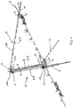
- the support 1 has a column head 2 and a column foot 4, between which a central support part 5 runs, which expires according to the representation selected in the figure in its upper region in the column head 5 and in its slope H adjacent lower portion arranged in the column foot. 4 ends.
- the support 1 or its central support part 5 has a side downwards, that is to say in the figure, downward-pointing side 6 and a side 7 pointing upwards.
- the support 1 is provided with a guy rope arrangement indicated in its entirety by the reference numeral 8.
- the guy rope assembly 8 comprises a rope comprising two rope sections 8A and 8B.
- the cable section 8A extends from its first end 9, which is fixed to a ground anchor (tie rod) 10, to the column head 1, 2 and extends, as can be seen from the figure, over a cable deflection device 11.
- a second cable section 8B extends to the column foot 4, where the second end 12 of the rope formed in its entirety by the cable sections 8A and 8B is fixed by means of a second ground anchor 3 in the underground of the slope H.
- This ground anchor 3 may be a push / pull anchor.
- the Seilumlenk beautiful 11 has in the figure, particularly preferred embodiment, a rotatable roller 11 A on. Further, the figure shows that an energy absorbing means 13 (e.g., a rope brake) may be disposed in the region of the second end 12.
- an energy absorbing means 13 e.g., a rope brake
- the angles which the cable sections 8A and 8B occupy to the slope H, respectively, are selectable according to the anticipated absorbing forces in the construction of the support 1.
- a second cable arrangement consisting of the cable sections 8'A and 8'B, is also shown by dashed lines.
- the cable section 8'A extends from its first end 9 ', which is attached to a ground anchor 10', to the cable deflection device 11, which in this embodiment has a second deflection roller 11 B, which is also shown in dashed lines.
- the second cable section 8'B extends from the deflection roller 11B via a second, preferably to be provided Seilumlenk issued 14 (with further preferably rotatably mounted roller 14A) to a second ground anchor (tie rod 3 ') to which the second end 12' is fixed.
- the guy cable arrangement 8 can comprise either only the arrangement of the cable sections 8A and 8B or 8'A and 8'B as well as a combination of these cable arrangements with the respective deflection devices 11 and 14, as can be seen from the drawing ,
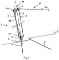
- Fig. 2 it is possible to provide two ropes guided in parallel at the same height corresponding to the cable sections 8A and 8B, the cable deflection device 11 then having two deflection rollers 11A arranged side by side at the same height.
- a corresponding arrangement is also conceivable with respect to the cable sections 8'A and 8'B, as well as a combination of these two cable arrangements.
- the pulleys 11A of which in Fig. 2 due to the selected representation only one guide roller 11A is visible, on both sides of the support 1, that is arranged on both sides of the support head 2, laterally to the central part 5.
- the two cable sections 8B extend after deflection by this deflecting device 11 at least approximately to the middle of the column foot 4.
- the two cable sections 8B are fixed again by ground anchors 3 laterally of the column foot 4 in the underground of the slope H.
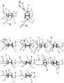
- FIGS. 3A to 3L Alternative embodiments of the support 1 according to the invention are shown, wherein a highly schematically simplified representation is selected.
- the support 1 is hereby shown in plan view in a view of the support head 2, the guy rope arrangement is in each case designated by the reference numeral 8.
- the point 11 respectively represents the Seilumlenk listening and the reference numerals 6 and 7 represent according to the embodiment of the FIGS. 1 and 2 the slope-down-facing side of the support 1 and the middle support part 5 or in the case of the reference numeral 7, the uphill-facing side of the support 1 and the middle support part 5 is.
- a guy rope assembly 8 comprising a rope, as in the case of the embodiment according to FIG. 1 described with reference to the cable assembly 8'A, 8'B.
- the Seilumlenk prepared 11 is disposed on the uphill side facing 7, while in the embodiment according to FIG. 3B is provided on the downhill side 6.
- Lashing cable assemblies 8 are provided, each comprising two ropes, which are accordingly deflected in each case via a Seilumlenk Republic 11 with two deflection points, so for example two pulleys.
- the embodiments according to the Figures 3C and 3D correspond in principle to those of FIGS. 3A and 3B , wherein, as said, two ropes each form a guy rope arrangement.
- the free ends of these cable arrangements can be summarized via a ground anchor or separately fixed over two ground anchors.
- a Seilumlenk Republic 11 is arranged on the uphill side facing 7 and the other on the downhill side 6, as this results in detail from the drawing.
- a guy rope assembly 8 is provided, which is transferred from two substantially V-shaped guided ropes in a cable section 8C, which then in each case via a Seilumlenk issued 11 in a case on the uphill side 7 and in the case of FIG. 3H is deflected on the downhill side 6 of the support 1.
- FIGS. 3I and 3J represent embodiments in which the guy rope assembly 8 have first V-shaped converging cable sections and then parallel to each other cable sections, but via two Seilumlenk noticeden or two pulleys once on the uphill side facing 7 and in the case of FIG. 3J be redirected on the downhill side 6.
- the guy rope assembly 8 also has two ropes, wherein the rope 8E is deflected over a cable guide 11 arranged on the uphill side 7, while the rope 8 of FIG Abspannseilan Aunt 8 is deflected on the downhill side 6 via a deflecting device 11.
- FIG. 3L Finally shows a guy rope arrangement with ropes 8F and 8G, which are respectively deflected by Seilumlenk Anlagenen 11, which are arranged approximately in the middle of the support 1 next to the support head 2 and from there reroute the ropes 8F and 8G in the slope, the side of the column foot 4th in the underground.
- a reduction in the armature forces is achieved because not only a mountain-side restraining rope (which would correspond to the rope sections 8A and 8'A, respectively) is provided, but a guy rope assembly 8 with rope deflector 11 and / or 14, as they are previously explained according to the different embodiments.
Description
Die Erfindung betrifft eine Stütze einer Steinschlagverbauung gemäß dem Oberbegriff des Anspruches 1.The invention relates to a support of a Steinschlagverbauung according to the preamble of
Eine derartige Stütze ist aus der
Um die auf die Steinschlagverbauung einwirkenden Kräfte aufzunehmen, sind die Stützen u.a. mittels bergseitiger Rückhalteseile gehalten, die an einem Ende am Stützenkopf angreifen und an ihrem anderen Ende beispielsweise über Bodenanker (Zuganker oder kombinierte Druck-/Zuganker) im Untergrund fixiert werden.In order to absorb the forces acting on the Steinschlagverbauung forces, the supports u.a. held by means of mountain-side restraint ropes which engage at one end on the column head and at its other end, for example, via ground anchors (tie rods or combined pressure / tension anchor) are fixed in the ground.
Es ist Aufgabe der vorliegenden Erfindung, eine Stütze der im Oberbegriff des Anspruches 1 angegebenen Art zu schaffen, die eine Minimierung bzw. zumindest Reduzierung der auftretenden Ankerkräfte ermöglicht.It is an object of the present invention to provide a support of the type specified in the preamble of
Die Lösung dieser Aufgabe erfolgt durch die Merkmale des Anspruches 1.The solution of this object is achieved by the features of
Dementsprechend ist erfindungsgemäß vorgesehen, dass am Stützenkopf eine Seilumlenkeinrichtung vorgesehen ist, über das bzw. die Seile einer Abspannseilanordnung geführt werden können. Ein Ende des Seile bzw. die Enden der Seile, falls die Abspannseilanordnung mehrere Seile aufweist, sind hierbei an einem ersten Bodenanker angebracht, der auf der Bergseite, also oberhalb der Stütze im Hang fixiert ist. Das andere über die Seilumlenkeinrichtung geführte Ende des Seile (bzw. der Seile) wird an einem zweiten Bodenanker angebracht, der je nach der Art der Ausführungsform, die nachfolgend im Einzelnen beschrieben werden, talseitig, also unterhalb der Stütze bzw. ebenfalls bergseitig, im Untergrund fixiert sind.Accordingly, the invention provides that on the column head a Seilumlenkeinrichtung is provided, via which or the ropes of a guy rope arrangement can be performed. One end of the rope or the ends of the ropes, if the guy rope arrangement has a plurality of cables, are in this case attached to a first ground anchor, which is fixed on the mountain side, ie above the support in the slope. The other guided over the Seilumlenkeinrichtung end of the rope (or ropes) is attached to a second ground anchor, depending on the type of embodiment, which will be described in detail below, the valley, ie below the support or also on the mountain side, in the underground are fixed.
Die Unteransprüche haben vorteilhafte Weiterbildungen der Erfindungen zum Inhalt.The dependent claims have advantageous developments of the inventions to the content.
Aus der
Wie zuvor bereits erläutert, kann die Abspannseilanordnung lediglich ein Seil aufweisen, das vom bergseitigen Bodenanker (Zuganker) zum Stützenkopf und über die Seilumlenkeinrichtung zum Stützenfuß geführt wird. Bei einer Ausführungsform ist das fußseitige Ende des Seiles der Abspannseilanordnung mit einem Bodenanker verbindbar, der talseitig, also unterhalb der Stütze im Untergrund fixiert wird.As already explained above, the guy rope arrangement can only comprise a cable which is guided by the mountain-side ground anchor (tie rod) to the column head and via the cable deflection device to the column foot. In one embodiment, the foot-side end of the rope of the guy rope assembly is connectable to a ground anchor, which is fixed in the ground, so below the support in the ground.
Bei einer alternativen Ausführungsform weist die Abspannseilanordnung pro Stütze ebenfalls lediglich ein Seil auf, das bergseitig, also oberhalb der Stütze, mit seinem ersten Ende wiederum über einen Bodenanker im Untergrund fixiert ist, dann allerdings über die am Stützenkopf angeordnete Seilumlenkeinrichtung zum Stützenfuß auf der Bergseite der Stütze, also oberhalb der Stütze geführt und dort gegebenenfalls nochmals über eine zweite Umlenkeinrichtung zu einem Bodenanker geführt wird.In an alternative embodiment, the guy rope assembly per support also only a rope on the mountain side, so above the support, in turn fixed with its first end via a ground anchor in the ground, but then on the column head arranged Seilumlenkeinrichtung for Stützfußfuß on the mountain side of Support, that is guided above the support and there optionally again via a second deflection to a ground anchor is performed.
Bei einer weiteren denkbaren alternativen Ausführungsform ist es möglich, zwei Seile pro Stütze und Abspannseilanordnung vorzusehen, von denen eines mit seinem zweiten Ende talseitig und das andere im Bereich des Stützenfußes bergseitig, wie zuvor erläutert, angeordnet und fixiert wird.In a further conceivable alternative embodiment, it is possible to provide two ropes per support and guy rope arrangement, one of which is arranged and fixed at the valley side with its second end and the other in the region of the column foot, as explained above.
Bei einer weiteren denkbaren Ausführungsform ist es möglich, pro Stütze und Abspannseilanordnung zwei parallel auf gleicher Höhe geführte Seile vorzusehen, deren erste Enden wiederum bergseits der Stütze fixiert sind, während die zweiten Enden talseits der Stütze im Untergrund fixiert werden können. In diesem Falle weist die Seilumlemkeinrichtung zwei seitlich der Stütze am Stützenkopf angeordnete Umlenkrollen auf gleicher Höhe auf, über die die Seile geführt werden. In diesem Falle werden die jeweils zweiten Enden der beiden Seile beiderseits des Stützenfußes über Bodenanker und ggf. Energieabsorbierungseinrichtungen zumindest in etwa mittig des Stützenfußes im Untergrund fixiert.In a further conceivable embodiment, it is possible to provide per support and guy rope two parallel guided at the same height ropes, the first ends are in turn fixed on the mountain side of the support, while the second ends can be fixed tal talseits the support in the ground. In this case, the Seilumlemkeinrichtung two arranged laterally of the support on the column head deflection rollers at the same height over which the ropes are performed. In this case, the respective second ends of the two cables are fixed on both sides of the column foot via ground anchors and possibly energy absorbing devices at least approximately in the center of the column foot in the ground.
Weitere Einzelheiten, Vorteile und Merkmale der vorliegenden Erfindung ergeben sich aus nachfolgender Beschreibung von Ausführungsbeispielen anhand der Zeichnung. Darin zeigt:
-
Fig. 1 eine schematisch stark vereinfachte Darstellung einer ersten Ausführungsform einer erfindungsgemäßen Stütze, -
Fig. 2 eine derFig. 1 entsprechende Darstellung einer zweiten Ausführungsform, und -
Fig. 3A - L Draufsichten auf schematisch stark vereinfachte Darstellungen von Ausführungsformen der erfindungsgemäßen Stütze
-
Fig. 1 a schematically simplified view of a first embodiment of a support according to the invention, -
Fig. 2 one of theFig. 1 corresponding representation of a second embodiment, and -
Fig. 3A - L Top views of schematically simplified representations of embodiments of the support according to the invention
Die einzige Figur der Zeichnung zeigt in schematisch stark vereinfachter Darstellung eine Stütze 1 einer Steinschlagverbauung, die zur Vereinfachung der Erläuterung der Prinzipien vorliegender Erfindung nicht mit sämtlichen ihrer Bestandteile dargestellt ist. Im Einsatzfall weist die Steinschlagverbauung natürlich alle diese erforderlichen Teile, wie insbesondere eine Mehrzahl von über den Berghang H verteilter aufrecht stehender Stützen und ein Fangnetz auf, das mittels Seilen an den Stützen geführt und im Untergrund fixiert werden kann. Beispiele für derartige Steinschlagverbauungen können der gattungsgemäßen
Die Stütze 1 weist einen Stützenkopf 2 und einen Stützenfuß 4 auf, zwischen denen ein mittleres Stützenteil 5 verläuft, der gemäß der in der Figur gewählten Darstellung in seinem oberen Bereich im Stützenkopf 5 ausläuft und in seinem dem Hang H benachbart angeordneten unteren Bereich im Stützenfuß 4 endet.The
Aufgrund der in der Figur gezeigten Einbaustellung ergibt sich, dass die Stütze 1 bzw. ihr mittleres Stützenteil 5 eine hangabwärts, also in der Figur nach unten weisende Seite 6 und eine hangaufwärts weisende Seite 7 hat.Due to the installation position shown in the figure, it follows that the
Die Stütze 1 ist mit einer in ihrer Gesamtheit mit der Bezugsziffer 8 gekennzeichneten Abspannseilanordnung versehen.The
Gemäß einer ersten Ausführungsform weist die Abspannseilanordnung 8 ein Seil auf, das zwei Seilabschnitte 8A und 8B umfasst. Der Seilabschnitt 8A verläuft von seinem ersten Ende 9, das an einem Bodenanker (Zuganker) 10 fixiert ist, zum Stützenkopf 1, 2 und verläuft, wie sich aus der Figur ergibt, über eine Seilumlenkeinrichtung 11. Von dort verläuft ein zweiter Seilabschnitt 8B zum Stützenfuß 4, wo das zweite Ende 12 des in seiner Gesamtheit von den Seilabschnitten 8A und 8B gebildeten Seils mittels eines zweiten Bodenankers 3 im Untergrund des Hanges H fixiert ist. Dieser Bodenanker 3 kann ein Druck-/Zuganker sein.According to a first embodiment, the
Die Seilumlenkeinrichtung 11 weist bei der in der Figur dargestellten, besonders bevorzugten Ausführungsform eine drehbare Rolle 11 A auf. Ferner zeigt die Figur, dass im Bereich des zweiten Endes 12 eine Energieabsorbiereinrichtung 13 (z.B. eine Seilbremse) angeordnet sein kann.The
Die Winkel, die die Seilabschnitte 8A und 8B jeweils zum Hang H einnehmen, sind je nach den zu erwarten aufnehmenden Kräften bei der Konstruktion der Stütze 1 wählbar.The angles which the
In der Figur ist ferner strichliert eine zweite Seilanordnung, bestehend aus den Seilabschnitten 8'A und 8'B gezeigt. Der Seilabschnitt 8'A verläuft von seinem ersten Ende 9', das an einem Bodenanker 10' angebracht ist, zur Seilumlenkeinrichtung 11, die bei dieser Ausführungsform eine zweite Umlenkrolle 11 B aufweist, die ebenfalls strichliert eingezeichnet ist. Der zweite Seilabschnitt 8'B verläuft von der Umlenkrolle 11B über eine zweite, vorzugsweise vorzusehende Seilumlenkeinrichtung 14 (mit weiterer vorzugsweise drehbar gelagerter Rolle 14A) zu einem zweiten Bodenanker (Zuganker 3'), an dem das zweite Ende 12' fixiert ist.In the figure, a second cable arrangement, consisting of the cable sections 8'A and 8'B, is also shown by dashed lines. The cable section 8'A extends from its first end 9 ', which is attached to a ground anchor 10', to the
Gemäß den eingangs erläuterten alternativen Ausführungsformen kann die Abspannseilanordnung 8 entweder nur die Anordnung aus den Seilabschnitten 8A und 8B oder 8'A und 8'B sowie auch eine Kombination dieser Seilanordnungen mit den jeweiligen Umlenkeinrichtungen 11 und 14 umfassen, wie sich dies aus der Zeichnung ergibt.According to the alternative embodiments explained in the introduction, the
Ferner ist es gemäß
Die beiden Seilabschnitte 8B verlaufen nach Umlenkung durch diese Umlenkeinrichtung 11 zumindest in etwa zur Mitte des Stützenfußes 4. Hier werden die beiden Seilabschnitte 8B jeweils wieder durch Bodenanker 3 seitlich des Stützenfußes 4 im Untergrund des Hanges H fixiert.The two
In den
Gemäß der
Bei den Ausführungsformen gemäß den
Bei der Ausführungsform gemäß
Bei der Ausführungsform gemäß
Bei den Ausführungsformen gemäß den
Die
Bei der Ausführungsform gemäß
Die Ausführungsform gemäß der
In jedem Falle wird bei jeder der erläuterten Ausführungsformen eine Reduzierung der Ankerkräfte erreicht, da nicht nur ein bergseitiges Rückhalteseil (was den Seilabschnitten 8A bzw. 8'A entspräche) vorgesehen ist, sondern eine Abspannseilanordnung 8 mit Seilumlenkeinrichtung 11 und/oder 14, wie sie zuvor entsprechend den unterschiedlichen Ausführungsformen erläutert worden ist.In any case, in each of the illustrated embodiments, a reduction in the armature forces is achieved because not only a mountain-side restraining rope (which would correspond to the rope sections 8A and 8'A, respectively) is provided, but a
Neben der voranstehenden schriftlichen Offenbarung der Erfindung wird hiermit explizit auf deren zeichnerische Darstellung in der einzigen Figur Bezug genommen.In addition to the above written disclosure of the invention, reference is hereby explicitly made to the drawings in the single figure.
- 11
- Stützesupport
- 22
- Stützenkopfsupport your head
- 3, 3'3, 3 '
- Bodenankerground anchor
- 44
- Stützenfußbase support
- 55
- mittleres Stützenteilmiddle support part
- 66
- hangabwärts weisende Seite des mittleren Stützenteils 5downwardly facing side of the middle support part. 5
- 77
- hangaufwärts weisende Seite des mittleren Stützenteils 5Uphill-facing side of the middle support part. 5
- 88th
- AbspannseilanordnungGuy rope arrangement
- 8A,B, 8'A,B, 8C, 8D, 8E, 8F, 8G8A, B, 8'A, B, 8C, 8D, 8E, 8F, 8G
- Seilabschnitte bzw. SeileRope sections or ropes
- 9, 9'9, 9 '
- erstes Endefirst end
- 10, 10'10, 10 '
- Bodenankerground anchor
- 1111
- SeilumlenkeinrichtungSeilumlenkeinrichtung
- 11A,B11A, B
- Umlenkrollenguide rollers
- 12, 12'12, 12 '
- zweites Endesecond end
- 1313
- EnergieabsorbierungseinrichtungEnergy-absorbing
- 1414
- zweite Seilumlenkeinrichtungsecond Seilumlenkeinrichtung
- 14A14A
- Umlenkrolleidler pulley
- HH
- Hanghillside
Claims (10)
- Support (1) for a rock fall obstruction- having a support head (2);- having a column base (4);- having a central support part (5) which is arranged between the support head (2) and the column base (4) and which comprises a side (6) facing downhill in the assembled state and a side (7) facing uphill; and- having an anchoring cable arrangement (8), of which one end (9) can be connected to a first soil anchor (10),characterised in that- a cable deflection device (11) is arranged on the support head (2) and is used to guide the anchoring cable arrangement (8), of which the other end (12) can be connected to a second soil anchor (3), and- the cable deflection device (11) guides the other end (12) of the anchoring cable arrangement (8) to the column base (4).
- Support as claimed in claim 1, characterised in that the anchoring cable arrangement (8) comprises a cable (8A, 8B) and the first soil anchor (10) can be fixed in the subsurface on the uphill-facing side (7) of the central support part (5) and the second soil anchor (3) can be fixed in the subsurface on the downhill-facing side (6) of the central support part (5).
- Support as claimed in claim 1 or 2, characterised in that the cable (8A, 8B) of the anchoring cable arrangement (8) is provided in the region of the other end (12) with an energy absorption device (13).
- Support as claimed in claim 1, characterised in that the anchoring cable arrangement (8) comprises a cable (8'A, 8'B) and the first soil anchor (10') can be fixed in the subsurface on the uphill-facing side (7) and the second soil anchor (3') can be fixed in the subsurface likewise on the uphill-facing side (7) adjacent to the column base (4).
- Support as claimed in claim 4, characterised in that a second cable deflection device (14) is arranged adjacent to the column base (4) on the central support part (5).
- Support as claimed in any one of claims 2 to 5, characterised in that the anchoring cable arrangement (8) comprises two cables (8A, 8B and 8'A and 8'B), wherein the first soil anchor (10) of the first cable (8A, 8B) and the first soil anchor (10') of the second cable (8'A, 8'B) can be fixed in the subsurface on the uphill side (7) of the central support part (5) and the second soil anchor (3) of the first cable (8A, 8B) can be fixed in the subsurface on the downhill-facing side (6) of the central support part (5), whereas the second soil anchor (3') of the second cable (8'A, 8'B) can be fixed in the subsurface on the uphill-facing side (7) of the central support part (5).
- Support as claimed in claim 6, characterised in that a second cable deflection device (14) is arranged adjacent to the column base (4) on the central support part (5).
- Support as claimed in claim 2 or 3, characterised in that the anchoring cable arrangement (8) comprises two cables (8A, 8B) which are guided next to one another at the same height, and two first soil anchors (10) and two second soil anchors (3) are provided for fixing the two cables (8A, 8B) which are guided next to one another at the same height.
- Support as claimed in claim 1, characterised in that the cable deflection device (11) comprises at least one, preferably rotatably mounted, deflection roller (11 A, 11B).
- Support as claimed in claim 6, characterised in that the cable deflection device comprises two, preferably rotatably mounted, deflection rollers (11A) which are arranged at the same height on the support head (2).
Priority Applications (2)
| Application Number | Priority Date | Filing Date | Title |
|---|---|---|---|
| ES12006645.1T ES2593639T3 (en) | 2012-09-21 | 2012-09-21 | Support for protection against falling stones |
| EP12006645.1A EP2711461B1 (en) | 2012-09-21 | 2012-09-21 | Support for a rock fall obstruction |
Applications Claiming Priority (1)
| Application Number | Priority Date | Filing Date | Title |
|---|---|---|---|
| EP12006645.1A EP2711461B1 (en) | 2012-09-21 | 2012-09-21 | Support for a rock fall obstruction |
Publications (2)
| Publication Number | Publication Date |
|---|---|
| EP2711461A1 EP2711461A1 (en) | 2014-03-26 |
| EP2711461B1 true EP2711461B1 (en) | 2016-06-08 |
Family
ID=46969941
Family Applications (1)
| Application Number | Title | Priority Date | Filing Date |
|---|---|---|---|
| EP12006645.1A Active EP2711461B1 (en) | 2012-09-21 | 2012-09-21 | Support for a rock fall obstruction |
Country Status (2)
| Country | Link |
|---|---|
| EP (1) | EP2711461B1 (en) |
| ES (1) | ES2593639T3 (en) |
Families Citing this family (1)
| Publication number | Priority date | Publication date | Assignee | Title |
|---|---|---|---|---|
| CN111424573B (en) * | 2020-05-05 | 2021-08-17 | 西南交通大学 | Extensible modular energy-consumption protective net unit group and protective net system formed by same |
Family Cites Families (5)
| Publication number | Priority date | Publication date | Assignee | Title |
|---|---|---|---|---|
| FR2763083B1 (en) * | 1997-05-07 | 1999-07-02 | Sol Systemes | DYNAMIC FALLING STONE BARRIER WITH ENERGY DISSIPATION LOOP |
| DE19912237A1 (en) * | 1999-03-18 | 2000-10-19 | Fraunhofer Management Ges Mbh | Deriving avalanches with inclined areas |
| ES2345148T5 (en) * | 2003-07-24 | 2016-03-16 | Trumer Schutzbauten Gesmbh | Auxiliary energy absorption structure |
| EP1911884A1 (en) | 2006-10-13 | 2008-04-16 | Trumer Schutzbauten GesmbH | Support for protection against falling rocks |
| EP2489785B1 (en) | 2011-02-17 | 2014-10-15 | Trumer Schutzbauten GesmbH | Rock fall obstruction |
-
2012
- 2012-09-21 EP EP12006645.1A patent/EP2711461B1/en active Active
- 2012-09-21 ES ES12006645.1T patent/ES2593639T3/en active Active
Also Published As
| Publication number | Publication date |
|---|---|
| ES2593639T3 (en) | 2016-12-12 |
| EP2711461A1 (en) | 2014-03-26 |
Similar Documents
| Publication | Publication Date | Title |
|---|---|---|
| EP2794997B1 (en) | Protection structure | |
| EP2489785B1 (en) | Rock fall obstruction | |
| DE202006020257U1 (en) | Traffic-guide assembly | |
| EP1645691B1 (en) | Transition structure | |
| DE202005006224U1 (en) | Crash dampener for use in front of barricade at traffic lanes has pre-determined number of dampener elements, which are adjustably arranged before barricade wherein crash dampener is also anchored by means of anchorage in the underground | |
| DE102007024993B4 (en) | Vehicle restraint system on traffic routes | |
| EP2286033B1 (en) | Vehicle restraint system | |
| EP2711461B1 (en) | Support for a rock fall obstruction | |
| DE3629935A1 (en) | FENCE | |
| EP2108742A2 (en) | Vehicle retention system | |
| DE102006053341A1 (en) | Concrete guide wall for trapping vehicle, has rope loop connecting concrete guide wall with adjacent concrete guide wall at its front surface, where rope loop projects over front surface of concrete guide wall | |
| EP2725139B1 (en) | Protection fence for protecting against rock fall | |
| WO2015019140A1 (en) | Post for a rockfall catching net and rockfall catching net | |
| DE202014102250U1 (en) | Dynamic rockfall protection barrier | |
| DE1534538A1 (en) | Security fence | |
| EP3309299B1 (en) | Protective structure | |
| DE4315286C2 (en) | Prefabricated anchor element, especially for passive protective devices | |
| DE102016119836A1 (en) | Guard rail arrangement with anchor posts | |
| EP3907330B1 (en) | Rock fall obstruction | |
| DE102006041362B4 (en) | The transition structure | |
| EP2927373B1 (en) | Vehicle restraint system with front end/terminal | |
| EP2927374B1 (en) | Vehicle restraint system with front end/terminal | |
| EP2607746A1 (en) | Cable brake assembly | |
| AT289180B (en) | Guardrail section set up for opening | |
| EP1921211A1 (en) | Traffic guidance device |
Legal Events
| Date | Code | Title | Description |
|---|---|---|---|
| PUAI | Public reference made under article 153(3) epc to a published international application that has entered the european phase |
Free format text: ORIGINAL CODE: 0009012 |
|
| AK | Designated contracting states |
Kind code of ref document: A1 Designated state(s): AL AT BE BG CH CY CZ DE DK EE ES FI FR GB GR HR HU IE IS IT LI LT LU LV MC MK MT NL NO PL PT RO RS SE SI SK SM TR |
|
| AX | Request for extension of the european patent |
Extension state: BA ME |
|
| 17P | Request for examination filed |
Effective date: 20140924 |
|
| RBV | Designated contracting states (corrected) |
Designated state(s): AL AT BE BG CH CY CZ DE DK EE ES FI FR GB GR HR HU IE IS IT LI LT LU LV MC MK MT NL NO PL PT RO RS SE SI SK SM TR |
|
| GRAP | Despatch of communication of intention to grant a patent |
Free format text: ORIGINAL CODE: EPIDOSNIGR1 |
|
| INTG | Intention to grant announced |
Effective date: 20151217 |
|
| GRAS | Grant fee paid |
Free format text: ORIGINAL CODE: EPIDOSNIGR3 |
|
| GRAA | (expected) grant |
Free format text: ORIGINAL CODE: 0009210 |
|
| AK | Designated contracting states |
Kind code of ref document: B1 Designated state(s): AL AT BE BG CH CY CZ DE DK EE ES FI FR GB GR HR HU IE IS IT LI LT LU LV MC MK MT NL NO PL PT RO RS SE SI SK SM TR |
|
| REG | Reference to a national code |
Ref country code: GB Ref legal event code: FG4D Free format text: NOT ENGLISH |
|
| REG | Reference to a national code |
Ref country code: CH Ref legal event code: EP |
|
| REG | Reference to a national code |
Ref country code: IE Ref legal event code: FG4D Free format text: LANGUAGE OF EP DOCUMENT: GERMAN |
|
| REG | Reference to a national code |
Ref country code: AT Ref legal event code: REF Ref document number: 805350 Country of ref document: AT Kind code of ref document: T Effective date: 20160715 |
|
| REG | Reference to a national code |
Ref country code: DE Ref legal event code: R096 Ref document number: 502012007332 Country of ref document: DE |
|
| REG | Reference to a national code |
Ref country code: FR Ref legal event code: PLFP Year of fee payment: 5 |
|
| REG | Reference to a national code |
Ref country code: LT Ref legal event code: MG4D |
|
| REG | Reference to a national code |
Ref country code: NL Ref legal event code: MP Effective date: 20160608 |
|
| PG25 | Lapsed in a contracting state [announced via postgrant information from national office to epo] |
Ref country code: FI Free format text: LAPSE BECAUSE OF FAILURE TO SUBMIT A TRANSLATION OF THE DESCRIPTION OR TO PAY THE FEE WITHIN THE PRESCRIBED TIME-LIMIT Effective date: 20160608 Ref country code: LT Free format text: LAPSE BECAUSE OF FAILURE TO SUBMIT A TRANSLATION OF THE DESCRIPTION OR TO PAY THE FEE WITHIN THE PRESCRIBED TIME-LIMIT Effective date: 20160608 Ref country code: NO Free format text: LAPSE BECAUSE OF FAILURE TO SUBMIT A TRANSLATION OF THE DESCRIPTION OR TO PAY THE FEE WITHIN THE PRESCRIBED TIME-LIMIT Effective date: 20160908 |
|
| REG | Reference to a national code |
Ref country code: CH Ref legal event code: NV Representative=s name: KELLER AND PARTNER PATENTANWAELTE AG, CH |
|
| PG25 | Lapsed in a contracting state [announced via postgrant information from national office to epo] |
Ref country code: RS Free format text: LAPSE BECAUSE OF FAILURE TO SUBMIT A TRANSLATION OF THE DESCRIPTION OR TO PAY THE FEE WITHIN THE PRESCRIBED TIME-LIMIT Effective date: 20160608 Ref country code: GR Free format text: LAPSE BECAUSE OF FAILURE TO SUBMIT A TRANSLATION OF THE DESCRIPTION OR TO PAY THE FEE WITHIN THE PRESCRIBED TIME-LIMIT Effective date: 20160909 Ref country code: SE Free format text: LAPSE BECAUSE OF FAILURE TO SUBMIT A TRANSLATION OF THE DESCRIPTION OR TO PAY THE FEE WITHIN THE PRESCRIBED TIME-LIMIT Effective date: 20160608 Ref country code: LV Free format text: LAPSE BECAUSE OF FAILURE TO SUBMIT A TRANSLATION OF THE DESCRIPTION OR TO PAY THE FEE WITHIN THE PRESCRIBED TIME-LIMIT Effective date: 20160608 Ref country code: NL Free format text: LAPSE BECAUSE OF FAILURE TO SUBMIT A TRANSLATION OF THE DESCRIPTION OR TO PAY THE FEE WITHIN THE PRESCRIBED TIME-LIMIT Effective date: 20160608 Ref country code: HR Free format text: LAPSE BECAUSE OF FAILURE TO SUBMIT A TRANSLATION OF THE DESCRIPTION OR TO PAY THE FEE WITHIN THE PRESCRIBED TIME-LIMIT Effective date: 20160608 |
|
| REG | Reference to a national code |
Ref country code: ES Ref legal event code: FG2A Ref document number: 2593639 Country of ref document: ES Kind code of ref document: T3 Effective date: 20161212 |
|
| PG25 | Lapsed in a contracting state [announced via postgrant information from national office to epo] |
Ref country code: CZ Free format text: LAPSE BECAUSE OF FAILURE TO SUBMIT A TRANSLATION OF THE DESCRIPTION OR TO PAY THE FEE WITHIN THE PRESCRIBED TIME-LIMIT Effective date: 20160608 Ref country code: RO Free format text: LAPSE BECAUSE OF FAILURE TO SUBMIT A TRANSLATION OF THE DESCRIPTION OR TO PAY THE FEE WITHIN THE PRESCRIBED TIME-LIMIT Effective date: 20160608 Ref country code: IS Free format text: LAPSE BECAUSE OF FAILURE TO SUBMIT A TRANSLATION OF THE DESCRIPTION OR TO PAY THE FEE WITHIN THE PRESCRIBED TIME-LIMIT Effective date: 20161008 Ref country code: SK Free format text: LAPSE BECAUSE OF FAILURE TO SUBMIT A TRANSLATION OF THE DESCRIPTION OR TO PAY THE FEE WITHIN THE PRESCRIBED TIME-LIMIT Effective date: 20160608 Ref country code: EE Free format text: LAPSE BECAUSE OF FAILURE TO SUBMIT A TRANSLATION OF THE DESCRIPTION OR TO PAY THE FEE WITHIN THE PRESCRIBED TIME-LIMIT Effective date: 20160608 |
|
| PG25 | Lapsed in a contracting state [announced via postgrant information from national office to epo] |
Ref country code: PT Free format text: LAPSE BECAUSE OF FAILURE TO SUBMIT A TRANSLATION OF THE DESCRIPTION OR TO PAY THE FEE WITHIN THE PRESCRIBED TIME-LIMIT Effective date: 20161010 Ref country code: BE Free format text: LAPSE BECAUSE OF NON-PAYMENT OF DUE FEES Effective date: 20160930 Ref country code: SM Free format text: LAPSE BECAUSE OF FAILURE TO SUBMIT A TRANSLATION OF THE DESCRIPTION OR TO PAY THE FEE WITHIN THE PRESCRIBED TIME-LIMIT Effective date: 20160608 Ref country code: PL Free format text: LAPSE BECAUSE OF FAILURE TO SUBMIT A TRANSLATION OF THE DESCRIPTION OR TO PAY THE FEE WITHIN THE PRESCRIBED TIME-LIMIT Effective date: 20160608 |
|
| REG | Reference to a national code |
Ref country code: DE Ref legal event code: R097 Ref document number: 502012007332 Country of ref document: DE |
|
| PLBE | No opposition filed within time limit |
Free format text: ORIGINAL CODE: 0009261 |
|
| STAA | Information on the status of an ep patent application or granted ep patent |
Free format text: STATUS: NO OPPOSITION FILED WITHIN TIME LIMIT |
|
| PG25 | Lapsed in a contracting state [announced via postgrant information from national office to epo] |
Ref country code: MC Free format text: LAPSE BECAUSE OF FAILURE TO SUBMIT A TRANSLATION OF THE DESCRIPTION OR TO PAY THE FEE WITHIN THE PRESCRIBED TIME-LIMIT Effective date: 20160608 |
|
| 26N | No opposition filed |
Effective date: 20170309 |
|
| GBPC | Gb: european patent ceased through non-payment of renewal fee |
Effective date: 20160921 |
|
| PG25 | Lapsed in a contracting state [announced via postgrant information from national office to epo] |
Ref country code: SI Free format text: LAPSE BECAUSE OF FAILURE TO SUBMIT A TRANSLATION OF THE DESCRIPTION OR TO PAY THE FEE WITHIN THE PRESCRIBED TIME-LIMIT Effective date: 20160608 Ref country code: DK Free format text: LAPSE BECAUSE OF FAILURE TO SUBMIT A TRANSLATION OF THE DESCRIPTION OR TO PAY THE FEE WITHIN THE PRESCRIBED TIME-LIMIT Effective date: 20160608 |
|
| REG | Reference to a national code |
Ref country code: IE Ref legal event code: MM4A |
|
| PG25 | Lapsed in a contracting state [announced via postgrant information from national office to epo] |
Ref country code: IE Free format text: LAPSE BECAUSE OF NON-PAYMENT OF DUE FEES Effective date: 20160921 Ref country code: GB Free format text: LAPSE BECAUSE OF NON-PAYMENT OF DUE FEES Effective date: 20160921 |
|
| PG25 | Lapsed in a contracting state [announced via postgrant information from national office to epo] |
Ref country code: LU Free format text: LAPSE BECAUSE OF NON-PAYMENT OF DUE FEES Effective date: 20160921 |
|
| REG | Reference to a national code |
Ref country code: FR Ref legal event code: PLFP Year of fee payment: 6 |
|
| REG | Reference to a national code |
Ref country code: BE Ref legal event code: MM Effective date: 20160930 |
|
| PG25 | Lapsed in a contracting state [announced via postgrant information from national office to epo] |
Ref country code: HU Free format text: LAPSE BECAUSE OF FAILURE TO SUBMIT A TRANSLATION OF THE DESCRIPTION OR TO PAY THE FEE WITHIN THE PRESCRIBED TIME-LIMIT; INVALID AB INITIO Effective date: 20120921 Ref country code: CY Free format text: LAPSE BECAUSE OF FAILURE TO SUBMIT A TRANSLATION OF THE DESCRIPTION OR TO PAY THE FEE WITHIN THE PRESCRIBED TIME-LIMIT Effective date: 20160608 |
|
| PG25 | Lapsed in a contracting state [announced via postgrant information from national office to epo] |
Ref country code: MT Free format text: LAPSE BECAUSE OF FAILURE TO SUBMIT A TRANSLATION OF THE DESCRIPTION OR TO PAY THE FEE WITHIN THE PRESCRIBED TIME-LIMIT Effective date: 20160608 Ref country code: MK Free format text: LAPSE BECAUSE OF FAILURE TO SUBMIT A TRANSLATION OF THE DESCRIPTION OR TO PAY THE FEE WITHIN THE PRESCRIBED TIME-LIMIT Effective date: 20160608 |
|
| PG25 | Lapsed in a contracting state [announced via postgrant information from national office to epo] |
Ref country code: BG Free format text: LAPSE BECAUSE OF FAILURE TO SUBMIT A TRANSLATION OF THE DESCRIPTION OR TO PAY THE FEE WITHIN THE PRESCRIBED TIME-LIMIT Effective date: 20160608 |
|
| REG | Reference to a national code |
Ref country code: FR Ref legal event code: PLFP Year of fee payment: 7 |
|
| PG25 | Lapsed in a contracting state [announced via postgrant information from national office to epo] |
Ref country code: TR Free format text: LAPSE BECAUSE OF FAILURE TO SUBMIT A TRANSLATION OF THE DESCRIPTION OR TO PAY THE FEE WITHIN THE PRESCRIBED TIME-LIMIT Effective date: 20160608 Ref country code: AL Free format text: LAPSE BECAUSE OF FAILURE TO SUBMIT A TRANSLATION OF THE DESCRIPTION OR TO PAY THE FEE WITHIN THE PRESCRIBED TIME-LIMIT Effective date: 20160608 |
|
| PGFP | Annual fee paid to national office [announced via postgrant information from national office to epo] |
Ref country code: CH Payment date: 20180924 Year of fee payment: 7 |
|
| REG | Reference to a national code |
Ref country code: CH Ref legal event code: PL |
|
| PG25 | Lapsed in a contracting state [announced via postgrant information from national office to epo] |
Ref country code: LI Free format text: LAPSE BECAUSE OF NON-PAYMENT OF DUE FEES Effective date: 20190930 Ref country code: CH Free format text: LAPSE BECAUSE OF NON-PAYMENT OF DUE FEES Effective date: 20190930 |
|
| PGFP | Annual fee paid to national office [announced via postgrant information from national office to epo] |
Ref country code: AT Payment date: 20230915 Year of fee payment: 12 |
|
| PGFP | Annual fee paid to national office [announced via postgrant information from national office to epo] |
Ref country code: FR Payment date: 20230919 Year of fee payment: 12 Ref country code: DE Payment date: 20230925 Year of fee payment: 12 |
|
| PGFP | Annual fee paid to national office [announced via postgrant information from national office to epo] |
Ref country code: ES Payment date: 20231019 Year of fee payment: 12 |
|
| PGFP | Annual fee paid to national office [announced via postgrant information from national office to epo] |
Ref country code: IT Payment date: 20230929 Year of fee payment: 12 |