EP1500539A1 - Toit ouvrant pour véhicule - Google Patents
Toit ouvrant pour véhicule Download PDFInfo
- Publication number
- EP1500539A1 EP1500539A1 EP04017418A EP04017418A EP1500539A1 EP 1500539 A1 EP1500539 A1 EP 1500539A1 EP 04017418 A EP04017418 A EP 04017418A EP 04017418 A EP04017418 A EP 04017418A EP 1500539 A1 EP1500539 A1 EP 1500539A1
- Authority
- EP
- European Patent Office
- Prior art keywords
- lid
- roof
- track
- slider
- sliding
- Prior art date
- Legal status (The legal status is an assumption and is not a legal conclusion. Google has not performed a legal analysis and makes no representation as to the accuracy of the status listed.)
- Withdrawn
Links
- 230000033001 locomotion Effects 0.000 claims abstract description 31
- 230000008878 coupling Effects 0.000 claims abstract description 21
- 238000010168 coupling process Methods 0.000 claims abstract description 21
- 238000005859 coupling reaction Methods 0.000 claims abstract description 21
- 230000007246 mechanism Effects 0.000 claims description 14
- 238000006073 displacement reaction Methods 0.000 claims description 5
- 230000004044 response Effects 0.000 claims description 2
- 230000003993 interaction Effects 0.000 description 2
- 239000002184 metal Substances 0.000 description 2
- 230000000630 rising effect Effects 0.000 description 2
- 238000007789 sealing Methods 0.000 description 2
- 230000007704 transition Effects 0.000 description 2
- 241000511343 Chondrostoma nasus Species 0.000 description 1
- 101100390736 Danio rerio fign gene Proteins 0.000 description 1
- 101100390738 Mus musculus Fign gene Proteins 0.000 description 1
- 238000005452 bending Methods 0.000 description 1
- 230000009194 climbing Effects 0.000 description 1
- 238000010276 construction Methods 0.000 description 1
- 230000001419 dependent effect Effects 0.000 description 1
- 238000005538 encapsulation Methods 0.000 description 1
- 230000002349 favourable effect Effects 0.000 description 1
- 238000000034 method Methods 0.000 description 1
- 230000004048 modification Effects 0.000 description 1
- 238000012986 modification Methods 0.000 description 1
- 230000008569 process Effects 0.000 description 1
- 230000029305 taxis Effects 0.000 description 1
Images


Classifications
-
- B—PERFORMING OPERATIONS; TRANSPORTING
- B60—VEHICLES IN GENERAL
- B60J—WINDOWS, WINDSCREENS, NON-FIXED ROOFS, DOORS, OR SIMILAR DEVICES FOR VEHICLES; REMOVABLE EXTERNAL PROTECTIVE COVERINGS SPECIALLY ADAPTED FOR VEHICLES
- B60J7/00—Non-fixed roofs; Roofs with movable panels, e.g. rotary sunroofs
- B60J7/02—Non-fixed roofs; Roofs with movable panels, e.g. rotary sunroofs of sliding type, e.g. comprising guide shoes
- B60J7/024—Non-fixed roofs; Roofs with movable panels, e.g. rotary sunroofs of sliding type, e.g. comprising guide shoes characterised by the height regulating mechanism of the sliding panel
Definitions
- the invention relates to a spoiler roof formed openable Vehicle roof with at least one lid carrier for a lid, which by means of a Ausstell- and displacement mechanism from a closed position in which he a Roof opening closes, with its trailing edge by pivoting the lid embarrassed and to expose the roof opening in flared condition in Roof longitudinal direction is displaced to the rear, wherein the lid carrier by means of a first sliding element and a second sliding element in the roof longitudinal direction in Spaced apart from each other, along a roof-fixed guide in Roof longitudinal direction slidably guided and provided with a sliding link, with the one also along the roof-fixed guide in the roof longitudinal direction slidably guided control slide is engaged.
- Such a vehicle roof is known from DE 100 55 790 A1.
- This is the first one Sliding element a pivotally mounted at the front end of the lid carrier Sliding shoe, while a second sliding element fixed to the lid carrier connected sliding shoe is provided.
- Ausstellund Moving mechanism for the lid it is difficult to cover the front edge in Control the opening and closing movements exactly so that on the one hand in the lid closed position a perfect seal in the region of the edge gap between the front edge of the lid and the front edge of the roof opening is ensured without undesirably high contact forces being necessary, and on the other hand, a squeezing or any other excessive Stress on the seal arrangement provided for this edge gap area is avoided when the lid leaves the closed position or in the Closed position retracts.
- the relatively simple means a improved control of the movement of the lid leading edge in particular in the allowed critical phases in which the lid leaves the closed position and in the closed position retracts.
- the second sliding element with the lid carrier is not rigid, but is connected via a coupling link during Lidewing movements is imprinted a forced movement, can be from the the cover front edge described track easily set as this for the respective roof construction including the used Sealing arrangement is particularly favorable to the previously outlined requirements to fulfill.
- the coupling member with the control slide preferably has a Slotted arrangement in operative connection.
- the point of articulation of the coupling member on the lid carrier and the second sliding element are useful at opposite longitudinal ends of the coupling member arranged.
- the linkage arrangement in the longitudinal direction of the Coupling link extending slide track and one with this slide track cooperating slider fixed to the control carriage, wherein the one part of the gate assembly forming slider at the same time part of a Arrangement can be, over which the control slide with the slide track of the Lid carrier is engaged.
- the raising and shifting mechanism can, for example, according to a preferred embodiment be designed so that in the immediate vicinity of Lid closed position the lid leading edge laterally substantially pure Moving movement executes. It can also be ensured that in the course an opening process in the center of the roof, the movement of the lid leading edge also in close to the lid closed position obliquely backwards upwards, because because of the roof curvature, the lid center is higher.
- the inventive Structure of the opening and shifting mechanism opens in this regard, however various variations.
- the second sliding element under the Influence of adjusting movements of the coupling member and possibly of Adjusting movements of the first sliding element along a roof-fixed Guideway preferably adjusted so that the Deckelausstellieri a limited lid shift movement is superimposed.
- the lid is in the flared condition with the control slide over the Coupling member for displacement movements in the roof longitudinal direction preferably lockable.
- the slide track of the coupling member with the Control slide connecting linkage arrangement advantageously a track section on, in the locked state to the slider of this link arrangement Movements in the roof longitudinal direction prevents, while the roof-mounted guide with a Arrangement is provided, which cooperates with the second sliding member to the Slider when sliding movements of the flared lid in locked To maintain state.
- the roof-mounted guide can in a conventional manner (DE 100 55 790 A1) a have rearwardly inclined sloping track section, the first Sliding element in the course of pivoting movements of the lid passes.
- roofproof Guide with a guide rail with a substantially U-shaped cross-section provided and is the control carriage along Steuerschlitten- guideways slidably guided, which are opposed to each other by far.
- the slide track of the lid carrier may in particular by a T-guide be formed.
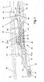
- Fig. 1 is a partial longitudinal section of a generally designated 10 vehicle spoiler roof shown having a lid 11 for selectively closing or Exposing a roof opening 12 which in a fixed roof skin 13th is trained.
- the required for issuing and moving the lid 11 Mechanism is similar on both sides of the lid 11. thats why Below only the one side of the cover associated mechanism using the Drawings explained in more detail.
- a roof fixedly arranged guide 15 with a guide rail 16 as Profile part is formed with guideways, in the with the Vehicle longitudinal direction coincident lid shift direction run.
- the facing each other at a distance and facing each other Pages are open, sliding jaws 19 of a control carriage 21 are longitudinally displaceable guided.
- the control carriage 21 is connected via a coupling member 22 with a in one further guide track 23 of the guide rail 16 guided longitudinally displaceable Drive cable 24 firmly connected.
- the drive cable 24 may be For example, to act a pressure-resistant threaded cable with a Drive pinion of a drive motor, not shown, is engaged.
- Control slide 21 has a hollow carriage body 26.
- the top of the carriage body 26 has wall portions 30, 31, the top of connect the longitudinal side walls 27 and a guide portion 32 of the Form control slide 21.
- the mutually facing free longitudinal edges of the Wall sections 30, 31 define a longitudinal slot 33, and the wall sections 30, 31 are bent up obliquely at the front and rear, as shown for example in FIG. 1 can be seen at 34.
- the control carriage 21 acts according to the figures 1 to 5 with a T-guide 36 in the form of an inverted T-shaped gate section of a in Vehicle longitudinal direction under the lid 11 extending lid carrier 37th together, with the lid 11 fixed to the relevant cover page connected, for example, screwed, is. Located on the other side of the cover a corresponding lid carrier.
- the T-guide 36 has in the illustrated Embodiment two substantially perpendicular, flat with each other connected sheet metal parts 38, 39, the lower ends in weg josder of each other Direction bent and to form a slide track 40 with good sliding Plastic 41 are overmoulded.
- the guide portion 32 of the carriage body 26 stands with the top of the slide track 40 in sliding engagement, while the investment roller 29 against the underside of the slide track 40 sets.
- the lid carrier 37 also has a forward projecting, of the Lid underside in spaced nose 42, which carries a shoe 44.
- a shoe 44 Of the Slider 44 is about a substantially horizontal Lid pivot axis 43 pivotally mounted.
- the axis 43 is at a distance of the underside of the lid 11 and is in the vehicle longitudinal direction with the Leading edge 45 at least approximately aligned.
- the shoe 44 is seated longitudinally displaceable depending on the lid position in at least one of the guideways 17, 18 of the guide rail 16 or in a guide track 47, to the front End of the guideways 17 and / or 18 connects and in a part the roof-fixed guide 15 forming, with the guide rail 16 firmly connected Lug 48 is formed.
- lid carrier 37 By means of the lid carrier 37 is thus the lid 11th in its front area at two in lid shift direction at a distance mutually facing points opposite the roof-fixed guide (Guide rail 16 and its endpiece 48) supported, on the one hand directly over the front shoe 44 and the other indirectly over the Control slide 21.
- Deckelverschiebraum Locking lever 50 On the lid carrier 37 is a extending in Deckelverschiebcardi Locking lever 50 at its front end via a bearing pin 51 in a substantially perpendicular plane rotatably mounted.
- the journal 51 is seated in Deckelverschiebides between the lid pivot axis 43 and the front End of the gate section 36.
- the locking lever 50 carries on his rear, in Deckelverschiebides near the rear end of the Sliding section 36 lying end a slider 52, which in a roof-fixed Sliding track 53 is guided when the lid in the area of its front End position is.
- the slide track 53 is in the illustrated Embodiment in a respect to the guide rail 16 fixed Gate block 54 is formed.
- the locking lever 50 is in turn with a elongated slide track 55 provided, in which the with the control slide 21 firmly connected bearing pin 28 engages in the manner of a sliding block slide to the Pivoting movement of the locking lever 50 relative to the lid carrier 37 to Taxes.
- the shoe 44 is located, in the transverse and vertical direction guided, in a substantially horizontally extending segment 58 of the Lug 48 certain guideway 47. He lies at least approximately below the front edge 59 of the roof opening 12.
- Der Bearing pin 28 is located near the front end of the slide track 55 of the Locking lever 50. He holds the locking lever 50 in a position in which of the rear end of the locking lever 50 arranged slider 52nd at the upper end of a steeply upwardly and forwardly inclined track section 60 of roof-fixed gate 53 stands.
- the guide portion 32 and the engagement roller 29 Stand with a front upright and essentially horizontal extending track portion 62 of the slide track 40 into engagement, whereby the lid 11 is pulled down.
- the slider 52 shifts in the steep track section 60 of the roof fixed Set of blocks 54 a short distance down.
- the lid will 11 moved back by a small amount, which is just enough to one Squeezing the seal assembly 65 in the region of the front edge 59 of the Avoid roof opening.
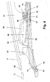
- the lid 11 leads to the transition from his Closed position shown in FIG. 1 in the flared position of FIG. 2 substantially a pivoting movement about the still in the segment 58 lid pivot axis 43 of the guide rail 47 located lid pivot axis 43 from.
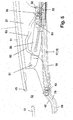
- the slider 52 becomes in a position near the lower end of the track portion 60 of the backdrop block 54 brought, which is only a minor further Displacement of the lid 11 is allowed to the rear in a position in which the Lid pivot axis 43, the transition from the web portion 58 to one after reaches behind obliquely rising track section 70 of the guideway 47.
- Of the Cover 11 is further issued with its trailing edge.
- Fig. 4 shows the raising and shifting mechanism 15 in a position in which-short after passing through the position shown in FIG. 3 - the lid pivot axis 43 in the web portion 70 of the guideway 47 has passed.
- the bearing pin 28 sets in the steep Web portion 71 of the formed in the locking lever 50 cam 55 one. He locked so the control carriage 21 via the locking lever 50 with the Lid carrier 37 for movements in Deckelverschiebraum.
- the slider 52 is now from the web portion 60 of the slide track 53 of the guide block 54 for a Adjustment movement to the rear in a direction in Deckelverschiebraum Rail section 72 of the slide 53 freed.
- the vehicle roof with several roof elements for example, lids, be provided, which may be fixed or adjustable.
- the explained structure also for double and multi-spoiler roofs.
- the described Cover carrier with T-guide offers high stability combined with particularly low Height.
- a lid carrier may also be provided in principle be in the usual way with a course of T-leadership more or less corresponding sliding slot is equipped.
- the guideway 47 and the slide track 53 in Bearing components of the guide rail 16, namely the extension piece 48 and the Guide block 54 are formed, the guide rail 16 itself as be formed simple profile component. Basically, but the Guideway 47 and / or the slide track 53 also provided in guide parts be connected in one piece with the guide rail.
Landscapes
- Engineering & Computer Science (AREA)
- Mechanical Engineering (AREA)
- Fittings On The Vehicle Exterior For Carrying Loads, And Devices For Holding Or Mounting Articles (AREA)
Applications Claiming Priority (2)
| Application Number | Priority Date | Filing Date | Title |
|---|---|---|---|
| DE10333781A DE10333781B4 (de) | 2003-07-24 | 2003-07-24 | Öffnungsfähiges Fahrzeugdach |
| DE10333781 | 2003-07-24 |
Publications (1)
| Publication Number | Publication Date |
|---|---|
| EP1500539A1 true EP1500539A1 (fr) | 2005-01-26 |
Family
ID=33483051
Family Applications (1)
| Application Number | Title | Priority Date | Filing Date |
|---|---|---|---|
| EP04017418A Withdrawn EP1500539A1 (fr) | 2003-07-24 | 2004-07-23 | Toit ouvrant pour véhicule |
Country Status (3)
| Country | Link |
|---|---|
| US (1) | US7104598B2 (fr) |
| EP (1) | EP1500539A1 (fr) |
| DE (1) | DE10333781B4 (fr) |
Cited By (4)
| Publication number | Priority date | Publication date | Assignee | Title |
|---|---|---|---|---|
| EP2017108A1 (fr) * | 2007-07-16 | 2009-01-21 | Inalfa Roof Systems Group B.V. | Construction décapotable pour véhicule |
| EP2108536A2 (fr) | 2008-04-03 | 2009-10-14 | Webasto AG | Toit de véhicule doté d'un capot réglable et d'un dispositif d'entraînement de capot |
| EP2263896A1 (fr) * | 2009-06-16 | 2010-12-22 | Inalfa Roof Systems Group B.V. | Construction décapotable pour véhicule |
| EP1690716B2 (fr) † | 2003-12-03 | 2016-06-15 | Aisin Seiki Kabushiki Kaisha | Dispositif de toit ouvrant |
Families Citing this family (15)
| Publication number | Priority date | Publication date | Assignee | Title |
|---|---|---|---|---|
| US9055984B2 (en) * | 2004-04-21 | 2015-06-16 | DePuy Synthes Products, Inc. | Sternal reconstruction system |
| US7704252B2 (en) | 2004-04-21 | 2010-04-27 | Synthes Usa, Llc | Sternal reconstruction system |
| DE102005054297B4 (de) * | 2005-11-11 | 2009-05-28 | Webasto Ag | Verstellbares Dachteil eines öffnungsfähigen Fahrzeugdaches |
| DE102005055383B3 (de) * | 2005-11-17 | 2007-01-18 | Webasto Ag | Fahrzeugdach eines Cabriolets mit bewegbarer Heckscheibe |
| DE102006002064B4 (de) | 2006-01-16 | 2008-03-20 | Webasto Ag | Fahrzeugdach mit einem oberhalb eines festen Dachabschnitts verschiebbaren Deckel |
| DE102007003354B4 (de) * | 2007-01-17 | 2009-08-06 | Webasto Ag | Fahrzeugdach mit einem oberhalb des Daches verschiebbaren Dachteil |
| EP2234831B1 (fr) * | 2009-02-09 | 2012-06-20 | Webasto AG | Mecanique pour un element de carrosserie deplaçable d'un vehicule |
| US8608182B2 (en) * | 2011-12-15 | 2013-12-17 | Skateone Corp. | Skateboard and skateboard truck |
| CN102897004A (zh) * | 2012-09-27 | 2013-01-30 | 江苏铁锚玻璃股份有限公司 | 一种汽车天窗用机械臂 |
| DE102014110234A1 (de) * | 2014-05-14 | 2015-11-19 | Webasto SE | Anordnung mit einem Deckel für ein Fahrzeugdach |
| DE102016125923A1 (de) * | 2016-12-30 | 2018-07-05 | Webasto SE | Anordnung für einen Deckel für ein Fahrzeugdach |
| US10532639B1 (en) * | 2018-09-06 | 2020-01-14 | AISIN Technical Center of America, Inc. | Holding assembly for a sunroof rail system |
| US10618387B2 (en) * | 2018-09-06 | 2020-04-14 | AISIN Technical Center of America, Inc. | Sunroof rail guide assembly |
| DE102018130016A1 (de) * | 2018-11-27 | 2020-05-28 | Roof Systems Germany Gmbh | Schiebedachsystem für ein Kraftfahrzeug |
| WO2020144100A1 (fr) * | 2019-01-11 | 2020-07-16 | Bos Gmbh & Co. Kg | Système d'entraînement conçu pour une pièce de toit mobile d'un système de toit d'un véhicule automobile |
Citations (4)
| Publication number | Priority date | Publication date | Assignee | Title |
|---|---|---|---|---|
| US4923246A (en) * | 1987-07-13 | 1990-05-08 | Ohi Seisakusho Co., Ltd. | Lid regulating device of sun roof structure |
| US5527085A (en) * | 1993-07-13 | 1996-06-18 | Aisin Seiki Kabushiki Kaisha | Sunroof device for vehicle |
| EP1046528A1 (fr) * | 1999-04-22 | 2000-10-25 | Inalfa Industries B.V. | Construction de toit ouvrant de véhicule |
| US20030075956A1 (en) * | 2001-09-21 | 2003-04-24 | Honda Giken Kogyo Kabushiki Kaisha And Yachiyo Kogyo Kabushiki Kaisha | Vehicle sun roof system |
Family Cites Families (7)
| Publication number | Priority date | Publication date | Assignee | Title |
|---|---|---|---|---|
| NL9101707A (nl) * | 1991-10-14 | 1993-05-03 | Vermeulen Hollandia Octrooien | Open-dakconstructie voor een voertuig. |
| DE10033887C1 (de) * | 2000-07-12 | 2001-08-30 | Webasto Vehicle Sys Int Gmbh | Fahrzeugdach mit wenigstens einem oberhalb des festen Fahrzeugdachs verschiebbaren Deckel |
| DE10046068B4 (de) * | 2000-09-15 | 2013-03-28 | Webasto Ag | Öffnungsfähiges Fahrzeugdach |
| DE10055790B4 (de) * | 2000-11-10 | 2005-03-17 | Webasto Ag | Öffnungsfähiges Fahrzeugdach |
| DE10065947C2 (de) * | 2000-12-23 | 2002-10-31 | Webasto Vehicle Sys Int Gmbh | Öffnungsfähiges Fahrzeugdach |
| DE10117322A1 (de) * | 2001-01-11 | 2002-07-25 | Webasto Vehicle Sys Int Gmbh | Fahrzeugdach |
| US6695398B2 (en) * | 2002-06-13 | 2004-02-24 | Webasto Sunroofs, Inc. | Spoiler sunroof mechanism |
-
2003
- 2003-07-24 DE DE10333781A patent/DE10333781B4/de not_active Expired - Fee Related
-
2004
- 2004-07-23 US US10/896,952 patent/US7104598B2/en active Active
- 2004-07-23 EP EP04017418A patent/EP1500539A1/fr not_active Withdrawn
Patent Citations (4)
| Publication number | Priority date | Publication date | Assignee | Title |
|---|---|---|---|---|
| US4923246A (en) * | 1987-07-13 | 1990-05-08 | Ohi Seisakusho Co., Ltd. | Lid regulating device of sun roof structure |
| US5527085A (en) * | 1993-07-13 | 1996-06-18 | Aisin Seiki Kabushiki Kaisha | Sunroof device for vehicle |
| EP1046528A1 (fr) * | 1999-04-22 | 2000-10-25 | Inalfa Industries B.V. | Construction de toit ouvrant de véhicule |
| US20030075956A1 (en) * | 2001-09-21 | 2003-04-24 | Honda Giken Kogyo Kabushiki Kaisha And Yachiyo Kogyo Kabushiki Kaisha | Vehicle sun roof system |
Cited By (7)
| Publication number | Priority date | Publication date | Assignee | Title |
|---|---|---|---|---|
| EP1690716B2 (fr) † | 2003-12-03 | 2016-06-15 | Aisin Seiki Kabushiki Kaisha | Dispositif de toit ouvrant |
| EP2017108A1 (fr) * | 2007-07-16 | 2009-01-21 | Inalfa Roof Systems Group B.V. | Construction décapotable pour véhicule |
| US7753438B2 (en) | 2007-07-16 | 2010-07-13 | Inalfa Roof Systems Group B.V. | Open roof construction for a vehicle |
| CN101367327B (zh) * | 2007-07-16 | 2012-08-15 | 银娜珐天窗系统集团股份有限公司 | 车辆的敞开的车顶结构 |
| EP2108536A2 (fr) | 2008-04-03 | 2009-10-14 | Webasto AG | Toit de véhicule doté d'un capot réglable et d'un dispositif d'entraînement de capot |
| EP2108536A3 (fr) * | 2008-04-03 | 2009-10-21 | Webasto AG | Toit de véhicule doté d'un capot réglable et d'un dispositif d'entraînement de capot |
| EP2263896A1 (fr) * | 2009-06-16 | 2010-12-22 | Inalfa Roof Systems Group B.V. | Construction décapotable pour véhicule |
Also Published As
| Publication number | Publication date |
|---|---|
| DE10333781B4 (de) | 2007-04-19 |
| DE10333781A1 (de) | 2005-02-17 |
| US20050017547A1 (en) | 2005-01-27 |
| US7104598B2 (en) | 2006-09-12 |
Similar Documents
| Publication | Publication Date | Title |
|---|---|---|
| DE10333781B4 (de) | Öffnungsfähiges Fahrzeugdach | |
| DE102005007031B4 (de) | Fahrzeugdach mit einem oberhalb des Daches verschiebbaren Dachteil | |
| EP1223065B1 (fr) | Toit de véhicule | |
| EP2234831B1 (fr) | Mecanique pour un element de carrosserie deplaçable d'un vehicule | |
| EP1844967A1 (fr) | Système de toit coulissant | |
| EP0638452B1 (fr) | Système de fermeture ou d'ouverture au moins partielle d'un couvercle pour toit basculant-coulissant | |
| EP1275541B1 (fr) | Module, spécialement module coulissant pour véhicule | |
| WO2018104019A1 (fr) | Système pour un panneau destiné à un toit de véhicule | |
| DE102016119450A1 (de) | Schiebedachsystem | |
| DE10158174B4 (de) | Schiebehebedach für Fahrzeuge | |
| EP0755815B1 (fr) | Toít pliant pour véhicule | |
| DE4001759C1 (en) | Sun roof for motor vehicles - has lever pivoting at end of sliding guide to actuate roof panel | |
| DE10237543A1 (de) | Fahrzeugdach | |
| DE202007001217U1 (de) | Fahrzeugdach mit einem oberhalb des Daches verschiebbaren Dachteil | |
| DE60009784T2 (de) | Konstruktion eines öffnungsfähigen Fahrzeugdaches | |
| EP1285798B1 (fr) | Toit de véhicule à déflecteur | |
| DE102004042450A1 (de) | Fahrzeugdach | |
| EP1743791A2 (fr) | Dispositif de fixation d'un rancher au niveau de la structure supérieure d'un véhicule utilitaire | |
| DE10226110B4 (de) | Fahrzeugdach | |
| EP2468548A2 (fr) | Dispositif de réglage d'une capote de toit pliable | |
| DE10258330B4 (de) | Versenkbares Fahrzeugdach | |
| DE102008026547B4 (de) | Faltdach eines Kraftfahrzeugs mit Ausstellspriegel | |
| DE10209901B4 (de) | Schiebehebedachanordnung mit Schiebehimmel | |
| DE102018130017A1 (de) | Schiebedachsystem für ein Kraftfahrzeug | |
| DE202018104104U1 (de) | Offendachkonstruktion für ein Fahrzeug |
Legal Events
| Date | Code | Title | Description |
|---|---|---|---|
| PUAI | Public reference made under article 153(3) epc to a published international application that has entered the european phase |
Free format text: ORIGINAL CODE: 0009012 |
|
| AK | Designated contracting states |
Kind code of ref document: A1 Designated state(s): AT BE BG CH CY CZ DE DK EE ES FI FR GB GR HU IE IT LI LU MC NL PL PT RO SE SI SK TR |
|
| AX | Request for extension of the european patent |
Extension state: AL HR LT LV MK |
|
| 17P | Request for examination filed |
Effective date: 20050310 |
|
| 17Q | First examination report despatched |
Effective date: 20050627 |
|
| AKX | Designation fees paid |
Designated state(s): DE FR GB NL |
|
| GRAP | Despatch of communication of intention to grant a patent |
Free format text: ORIGINAL CODE: EPIDOSNIGR1 |
|
| INTG | Intention to grant announced |
Effective date: 20131218 |
|
| STAA | Information on the status of an ep patent application or granted ep patent |
Free format text: STATUS: THE APPLICATION IS DEEMED TO BE WITHDRAWN |
|
| 18D | Application deemed to be withdrawn |
Effective date: 20140429 |