EP1500351A1 - Befestigungsvorrichtung für Schubladenfrontblenden - Google Patents
Befestigungsvorrichtung für Schubladenfrontblenden Download PDFInfo
- Publication number
- EP1500351A1 EP1500351A1 EP04009703A EP04009703A EP1500351A1 EP 1500351 A1 EP1500351 A1 EP 1500351A1 EP 04009703 A EP04009703 A EP 04009703A EP 04009703 A EP04009703 A EP 04009703A EP 1500351 A1 EP1500351 A1 EP 1500351A1
- Authority
- EP
- European Patent Office
- Prior art keywords
- block
- drawer
- spring
- support plate
- front panel
- Prior art date
- Legal status (The legal status is an assumption and is not a legal conclusion. Google has not performed a legal analysis and makes no representation as to the accuracy of the status listed.)
- Granted
Links
Images
Classifications
-
- A—HUMAN NECESSITIES
- A47—FURNITURE; DOMESTIC ARTICLES OR APPLIANCES; COFFEE MILLS; SPICE MILLS; SUCTION CLEANERS IN GENERAL
- A47B—TABLES; DESKS; OFFICE FURNITURE; CABINETS; DRAWERS; GENERAL DETAILS OF FURNITURE
- A47B88/00—Drawers for tables, cabinets or like furniture; Guides for drawers
- A47B88/90—Constructional details of drawers
- A47B88/944—Drawers characterised by the front panel
- A47B88/95—Drawers characterised by the front panel characterised by connection means for the front panel
- A47B88/956—Drawers characterised by the front panel characterised by connection means for the front panel for enabling adjustment of the front panel
Definitions
- the invention relates to a device for attaching a front panel Drawer rims according to the preamble of claim 1.
- Such fastening devices are known for example from DE 37 13 254 C, EP 0 289 866 B1 and EP 0 761 131 A2. These devices have each have a recess on the front side, into which a mounted on the front panel Block is inserted in such a way that the front ends of the drawer on both sides of provided in the block holding parts is included.
- a lock The front panel is made by fasteners that pass through the recess. According to the aforementioned prior art, these fasteners are made Screws.
- Object of the present invention is to provide a device of the initially mentioned To develop such a way that they can be placed without tools and again is detachable and that a height adjustment of the front panel is possible, without to operate appropriate fasteners.
- the front each have a recess into which a mounted on the front panel block, the Having a groove limiting holding parts, on each side of the drawer inserted in such a way is that the front ends of the drawer are on both sides of these Includes retaining members and passing through the recess fastening means be locked.
- the block has a projecting, parallel to the drawer facing leaf spring, in the assembled state with an edge a transversely angled projection in the region of the recess behind the drawer and where on the block one through an eccentric slidable support plate is guided, which is attached to the front panel.
- the block of several Parts are composed, the block having two separate holding parts can, between which the leaf spring is added.
- the support plate may advantageously have a partial C-shaped cross-section and slidably guided along vertical edges of the holding part.
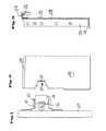
- FIG 1 is a front panel 10 with a protruding fastening device shown, in principle, a support plate 12, a leaf spring 14, a block 15 and an eccentric 16 is.
- a metal drawer 18 is in the Side view according to Figure 2 and shown in front view according to Figure 3.
- the front end of the drawer 18 has a recess 20 which is free extends to the outside and the edges are stepped.
- a projection 22 the rear edge of the recess to the outside to angled about 90 °. If the angle is slightly less than 90 °, then the Leaf spring 14 a small clamping force between the front panel 10 and drawer 18 exercise.
- the drawer 18 is in the usual way with a running rail 24, a roller 26 and angled parts 28 and 30, each for fixing one here not shown bottom and a rear wall of the drawer are provided provided. These parts are known as such and require no further description here.
- the block 15 may in principle be formed in one piece, wherein between two mutually parallel holding parts defining a groove, a central part arranged is formed, which is complementary to the recess 20 of the drawer is.
- the width of the groove corresponds to the height of this middle part and is something greater than the thickness of the drawer.
- the leaf spring 14 On one side of the groove is the leaf spring 14 inserted into the block and attached with this.
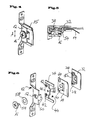
- FIGS. 4 to 6 show an expedient embodiment of the block 15. which consists of two separate holding parts 32 and 34.
- the holding part 32 has a, the recess 20 complementarily formed part 15, which by dowels 38 riveted after interposition of the leaf spring 14 with the other holding part 34 becomes.
- the leaf spring 14 and the holding part 34 is provided with bores 40 and 42.
- the leaf spring 14 is thus on the side of the holding parts 32 and 34 limited groove, the outer side of the drawer 18 corresponds to the projection 22 is arranged. So that the leaf spring is freely pivotable, the holding part 32 may be provided with a recess 44 be.
- the support plate 12 On vertical edges 46 and 48 of the holding part 34, the support plate 12 which partially has a C-shaped cross section, slidably guided.
- the support plate For training of the C-profile, the support plate has a nose 50, as in particular can be seen from the figure 6.
- An eccentric 16 passes through a slot 52 of the Support plate 12 and is with its shaft 54 in a bore 56 of the holding part 34th riveted.
- a spring washer 58 is mounted, the ensures a good contact force between the support plate 12 and block 15 and simultaneously allows an adjustment in the direction of the double arrow A (according to Figure 4).
- the support plate 12 is not described in detail here and usual manner with the Front panel 10 screwed.
- the leaf spring 14 is angled outwards in this way, that their operation to solve the connection without additional fittings possible is, with an assembly left and right guaranteed by the same device is.
Landscapes
- Drawers Of Furniture (AREA)
Abstract
Description
- Figur 1:
- eine Seitenansicht einer Frontblende mit einer erfindungsgemäßen Befestigungsvorrichtung,
- Figur 2:
- eine Teilseitenansicht einer Schubladenzarge,
- Figur 3:
- eine Frontansicht der Schubladenzarge gemäß Figur 2,
- Figur 4:
- eine perspektivische Ansicht eines Details der Befestigungsvorrichtung,
- Figur 5:
- einen Schnitt durch die Befestigungsvorrichtung gemäß Figur 4 im Einbauzustand an einer Zarge und
- Figur 6:
- eine Explosionszeichnung einer Befestigungsvorrichtung gemäß Figur 4.
Claims (9)
- Vorrichtung zur Befestigung einer Frontblende an Schubladenzargen, die stirnseitig je eine Ausnehmung aufweisen, in die ein an der Frontblende befestigter Block, der eine Nut begrenzende Halteteile aufweist, an jeder Seite der Schublade derart einschiebbar ist, daß die vorderen Enden der Schubladenzargen beidseitig von diesen Halteteilen umfaßt und von die Ausnehmung durchsetzenden Befestigungsmitteln verriegelt werden,
dadurch gekennzeichnet, daß der Block eine vorspringende, parallel zur Schubladenzarge gerichtete Blattfeder oder einen federbelasteten Hebel aufweist, die im montierten Zustand mit einem Rand einen quer abgewinkelten Vorsprung im Bereich der Ausnehmung der Schubladenzarge hintergreift und dass auf dem Block eine durch ein Exzenter verschiebliche Tragplatte geführt ist, die an der Frontblende befestigt ist. - Vorrichtung nach Anspruch 1, dadurch gekennzeichnet, daß der Block einstückig ausgebildet ist.
- Vorrichtung nach Anspruch 1, dadurch gekennzeichnet, daß der Block aus mehreren Teilen zusammengesetzt ist.
- Vorrichtung nach Anspruch 3, dadurch gekennzeichnet, daß der Block zwei getrennte Halteteile aufweist, zwischen denen die Blattfeder oder ein federbelasteter Hebel aufgenommen ist.
- Vorrichtung nach einem der Ansprüche 1 - 4, dadurch gekennzeichnet, daß die Tragplatte teilweise einen C-förmigen Querschnitt aufweist und entlang vertikaler Ränder des Halteteils verschieblich geführt ist.
- Vorrichtung nach Anspruch 5, dadurch gekennzeichnet, dass ein mit einem Kopf versehener Exzenter ein quergerichtetes Langloch der Tragplatte durchsetzt und mit seinem unteren exzentrischen Schaftteil in einer Bohrung des Halteteils vernietet ist.
- Vorrichtung nach Anspruch 6, dadurch gekennzeichnet, dass eine Federscheibe zwischen dem Kopf des Exzenters und der Tragplatte gelagert ist.
- Vorrichtung nach Anspruch 1, dadurch gekennzeichnet, dass die Blattfeder oder der federbelastete Hebel mit einem abgewinkelten Betätigungs- bzw. Entriegelungsteil versehen ist.
- Vorrichtung nach Anspruch 1 bis 8, dadurch gekennzeichnet, dass die Bestandteile symmetrisch zur mittleren Querachse für eine links- und rechts- Montage ausgebildet sind.
Applications Claiming Priority (2)
| Application Number | Priority Date | Filing Date | Title |
|---|---|---|---|
| DE20311190U DE20311190U1 (de) | 2003-07-21 | 2003-07-21 | Befestigungsvorrichtung für Schubladenfrontblenden |
| DE20311190U | 2003-07-21 |
Publications (2)
| Publication Number | Publication Date |
|---|---|
| EP1500351A1 true EP1500351A1 (de) | 2005-01-26 |
| EP1500351B1 EP1500351B1 (de) | 2006-06-21 |
Family
ID=28685641
Family Applications (1)
| Application Number | Title | Priority Date | Filing Date |
|---|---|---|---|
| EP04009703A Expired - Fee Related EP1500351B1 (de) | 2003-07-21 | 2004-04-23 | Befestigungsvorrichtung für Schubladenfrontblenden |
Country Status (8)
| Country | Link |
|---|---|
| US (1) | US7429090B2 (de) |
| EP (1) | EP1500351B1 (de) |
| CN (1) | CN1285303C (de) |
| AT (1) | ATE330507T1 (de) |
| DE (2) | DE20311190U1 (de) |
| ES (1) | ES2266950T3 (de) |
| HK (1) | HK1073236A1 (de) |
| TW (1) | TWI250003B (de) |
Families Citing this family (15)
| Publication number | Priority date | Publication date | Assignee | Title |
|---|---|---|---|---|
| JP3938187B2 (ja) | 2005-05-17 | 2007-06-27 | いすゞ自動車株式会社 | 排気ガス浄化方法及び排気ガス浄化システム |
| MY140411A (en) * | 2006-07-14 | 2009-12-31 | Harn Marketing Sdn Bhd | Drawer fitting |
| DE202007001783U1 (de) * | 2006-09-08 | 2008-01-10 | Paul Hettich Gmbh & Co. Kg | Verbindungseinrichtung an einem Schubkasten |
| DE102007053637A1 (de) * | 2007-11-08 | 2009-05-14 | Lautenschläger, Horst | Blendenhalter zur Befestigung einer Frontblende an einer Schubladenzarge |
| CN101181116B (zh) * | 2007-11-29 | 2011-03-16 | 罗志明 | 抽屉前面板与抽屉侧面板的连接装置 |
| AT511091B1 (de) * | 2011-04-19 | 2012-09-15 | Blum Gmbh Julius | Schubladenzarge mit neigungsverstellung |
| AT511062B1 (de) * | 2011-05-24 | 2012-09-15 | Blum Gmbh Julius | Befestigungsvorrichtung zum befestigen einer frontblende an einer schublade |
| AT510954B1 (de) * | 2011-05-24 | 2012-08-15 | Blum Gmbh Julius | Rastgesperre für möbelstücke |
| AT511538B1 (de) * | 2011-05-24 | 2013-06-15 | Blum Gmbh Julius | Befestigungsvorrichtung zum befestigen einer frontblende an einer schublade |
| ITMC20110058A1 (it) * | 2011-10-26 | 2013-04-27 | Essetre S R L | Cassetto perfezionato con anta frontale corredato di attrezzatura di regolazione e bloccaggio per detta anta frontale. |
| CN102525147B (zh) * | 2011-12-16 | 2014-06-18 | 伍志勇 | 抽屉面板调节装置 |
| CN102885494B (zh) * | 2012-10-25 | 2014-06-18 | 伍志勇 | 抽屉面板的调节装置 |
| US9185976B2 (en) * | 2014-04-08 | 2015-11-17 | King Slide Works Co., Ltd. | Adjusting device |
| US10499739B2 (en) | 2017-03-01 | 2019-12-10 | Worktools, Inc. | Transformable drawer front and countertop leaf |
| DE102017121385A1 (de) * | 2017-09-14 | 2019-03-14 | Paul Hettich Gmbh & Co. Kg | Blendenträger und Schubkasten |
Citations (3)
| Publication number | Priority date | Publication date | Assignee | Title |
|---|---|---|---|---|
| US4815798A (en) * | 1986-05-28 | 1989-03-28 | Julius Blum Gesellschaft M.B.H. | Holding device for the front plate of a drawer |
| US4995683A (en) * | 1987-12-07 | 1991-02-26 | Alfit Gesellschaft M.B.H. | Drawer provided with guide means |
| US6179399B1 (en) * | 1997-03-03 | 2001-01-30 | Julius Blum Gesellschaft M.B.H. | Fastening device for a drawer |
Family Cites Families (7)
| Publication number | Priority date | Publication date | Assignee | Title |
|---|---|---|---|---|
| DE3713254A1 (de) | 1986-05-14 | 1987-11-19 | Blum Gmbh Julius | Schublade |
| AT391409B (de) | 1987-05-04 | 1990-10-10 | Blum Gmbh Julius | Vorrichtung zur befestigung einer frontblende an metallischen schubladenzargen |
| US5281022A (en) * | 1991-04-02 | 1994-01-25 | Julius Blum Gesellschaft M.B.H. | Front panel mounting for drawers |
| AT405360B (de) | 1995-09-07 | 1999-07-26 | Alfit Ag | Vorrichtung zur einstellbaren befestigung der frontblende einer schublade an deren zargen |
| ES2199418T3 (es) * | 1997-04-29 | 2004-02-16 | Alfit Aktiengesellschaft | Cajon. |
| AT409070B (de) * | 1997-11-07 | 2002-05-27 | Alfit Ag | Vorrichtung zum befestigen der frontblende einer schublade |
| MY135151A (en) * | 2002-05-17 | 2008-02-29 | Harn Marketing Sdn Bhd | Drawer fitting arrangement |
-
2003
- 2003-07-21 DE DE20311190U patent/DE20311190U1/de not_active Expired - Lifetime
-
2004
- 2004-04-23 AT AT04009703T patent/ATE330507T1/de active
- 2004-04-23 ES ES04009703T patent/ES2266950T3/es not_active Expired - Lifetime
- 2004-04-23 DE DE502004000808T patent/DE502004000808D1/de not_active Expired - Lifetime
- 2004-04-23 EP EP04009703A patent/EP1500351B1/de not_active Expired - Fee Related
- 2004-06-18 TW TW093117578A patent/TWI250003B/zh not_active IP Right Cessation
- 2004-07-21 CN CNB2004100716821A patent/CN1285303C/zh not_active Expired - Fee Related
- 2004-07-21 US US10/896,245 patent/US7429090B2/en not_active Expired - Fee Related
-
2005
- 2005-07-11 HK HK05105881A patent/HK1073236A1/xx not_active IP Right Cessation
Patent Citations (3)
| Publication number | Priority date | Publication date | Assignee | Title |
|---|---|---|---|---|
| US4815798A (en) * | 1986-05-28 | 1989-03-28 | Julius Blum Gesellschaft M.B.H. | Holding device for the front plate of a drawer |
| US4995683A (en) * | 1987-12-07 | 1991-02-26 | Alfit Gesellschaft M.B.H. | Drawer provided with guide means |
| US6179399B1 (en) * | 1997-03-03 | 2001-01-30 | Julius Blum Gesellschaft M.B.H. | Fastening device for a drawer |
Also Published As
| Publication number | Publication date |
|---|---|
| ES2266950T3 (es) | 2007-03-01 |
| CN1575691A (zh) | 2005-02-09 |
| DE502004000808D1 (de) | 2006-08-03 |
| EP1500351B1 (de) | 2006-06-21 |
| TWI250003B (en) | 2006-03-01 |
| ATE330507T1 (de) | 2006-07-15 |
| TW200509838A (en) | 2005-03-16 |
| HK1073236A1 (en) | 2005-09-30 |
| DE20311190U1 (de) | 2003-09-25 |
| US20050017615A1 (en) | 2005-01-27 |
| US7429090B2 (en) | 2008-09-30 |
| CN1285303C (zh) | 2006-11-22 |
Similar Documents
| Publication | Publication Date | Title |
|---|---|---|
| EP1500351B1 (de) | Befestigungsvorrichtung für Schubladenfrontblenden | |
| AT510781A1 (de) | Möbelbeschlag zur frontblendenbefestigung | |
| EP2233676A2 (de) | Pfostenverbinder | |
| WO2018033465A1 (de) | Zarge für einen schubkasten | |
| EP1708591B1 (de) | Schubkasten | |
| DE102011011113B4 (de) | Rahmensystem eines Partikelschutzgitters | |
| EP3103948B1 (de) | Band für eine tür oder ein fenster | |
| EP0856626B1 (de) | Klemmbefestigungsvorrichtung für Beschlagteile | |
| DE1199159B (de) | Treibstangenverschluss, insbesondere Zentral-verschluss fuer Schwing- und Wendefluegelfenster od. dgl. | |
| DE202011104559U1 (de) | Vorrichtung mit einer Anbringeinrichtung zur lösbaren Verbindung eines Frontteils einer Schublade mit einer Profilleiste sowie Möbel | |
| DE202009003438U1 (de) | Pfostenverbinder | |
| EP2574716B1 (de) | Schiebetür oder -fenster mit einer Lüftungsvorrichtung und Arbeitsverfahren | |
| EP2540942B1 (de) | Verstellbare Beschlagsanordnung | |
| DE2701951C3 (de) | Beschlag für Schiebetüren | |
| DE60009377T2 (de) | Abstütz- und Führungsvorrichtung für die Treibstangenenden eines Treibstangenschlosses | |
| DE10255669B3 (de) | Seitenscheibe für ein Fahrzeug, insbesondere einen Personenkraftwagen | |
| DE10222731A1 (de) | Fenster, Tür od.dgl., Beschlaganordnung sowie Flügel hierfür | |
| DE60001627T2 (de) | Treibstangenschloss | |
| AT413725B (de) | Vorrichtung zum anschlagen eines ladens eines fensters oder einer tür | |
| DE1708125C (de) | Befestigung eines Schamierbeschlag teils an einer Fenster oder Türrahmen ecke | |
| EP0441161A2 (de) | Schubkasten mit aus Kunststoff oder Metall-Profilen bestehenden Seitenzargen | |
| EP2730732A2 (de) | Band für Türen, Fenster oder dergleichen | |
| AT413727B (de) | Vorrichtung zum anschlagen eines ladens eines fensters oder einer tür | |
| DE202006011986U1 (de) | Beschlag mit verstellbarem Riegel | |
| DE20013580U1 (de) | Tür, insbesondere Schiffstür |
Legal Events
| Date | Code | Title | Description |
|---|---|---|---|
| PUAI | Public reference made under article 153(3) epc to a published international application that has entered the european phase |
Free format text: ORIGINAL CODE: 0009012 |
|
| 17P | Request for examination filed |
Effective date: 20040507 |
|
| AK | Designated contracting states |
Kind code of ref document: A1 Designated state(s): AT BE BG CH CY CZ DE DK EE ES FI FR GB GR HU IE IT LI LU MC NL PL PT RO SE SI SK TR |
|
| AX | Request for extension of the european patent |
Extension state: AL HR LT LV MK |
|
| 17Q | First examination report despatched |
Effective date: 20050527 |
|
| AKX | Designation fees paid |
Designated state(s): AT DE ES IT |
|
| GRAP | Despatch of communication of intention to grant a patent |
Free format text: ORIGINAL CODE: EPIDOSNIGR1 |
|
| GRAS | Grant fee paid |
Free format text: ORIGINAL CODE: EPIDOSNIGR3 |
|
| GRAA | (expected) grant |
Free format text: ORIGINAL CODE: 0009210 |
|
| AK | Designated contracting states |
Kind code of ref document: B1 Designated state(s): AT DE ES IT |
|
| PG25 | Lapsed in a contracting state [announced via postgrant information from national office to epo] |
Ref country code: IT Free format text: LAPSE BECAUSE OF FAILURE TO SUBMIT A TRANSLATION OF THE DESCRIPTION OR TO PAY THE FEE WITHIN THE PRESCRIBED TIME-LIMIT;WARNING: LAPSES OF ITALIAN PATENTS WITH EFFECTIVE DATE BEFORE 2007 MAY HAVE OCCURRED AT ANY TIME BEFORE 2007. THE CORRECT EFFECTIVE DATE MAY BE DIFFERENT FROM THE ONE RECORDED. Effective date: 20060621 |
|
| REF | Corresponds to: |
Ref document number: 502004000808 Country of ref document: DE Date of ref document: 20060803 Kind code of ref document: P |
|
| REG | Reference to a national code |
Ref country code: ES Ref legal event code: FG2A Ref document number: 2266950 Country of ref document: ES Kind code of ref document: T3 |
|
| PLBE | No opposition filed within time limit |
Free format text: ORIGINAL CODE: 0009261 |
|
| STAA | Information on the status of an ep patent application or granted ep patent |
Free format text: STATUS: NO OPPOSITION FILED WITHIN TIME LIMIT |
|
| 26N | No opposition filed |
Effective date: 20070322 |
|
| PGRI | Patent reinstated in contracting state [announced from national office to epo] |
Ref country code: IT Effective date: 20080601 |
|
| PGFP | Annual fee paid to national office [announced via postgrant information from national office to epo] |
Ref country code: ES Payment date: 20120420 Year of fee payment: 9 |
|
| PGFP | Annual fee paid to national office [announced via postgrant information from national office to epo] |
Ref country code: AT Payment date: 20120425 Year of fee payment: 9 |
|
| PGFP | Annual fee paid to national office [announced via postgrant information from national office to epo] |
Ref country code: DE Payment date: 20130429 Year of fee payment: 10 |
|
| PGFP | Annual fee paid to national office [announced via postgrant information from national office to epo] |
Ref country code: IT Payment date: 20130422 Year of fee payment: 10 |
|
| REG | Reference to a national code |
Ref country code: DE Ref legal event code: R119 Ref document number: 502004000808 Country of ref document: DE |
|
| REG | Reference to a national code |
Ref country code: AT Ref legal event code: MM01 Ref document number: 330507 Country of ref document: AT Kind code of ref document: T Effective date: 20140423 |
|
| REG | Reference to a national code |
Ref country code: DE Ref legal event code: R119 Ref document number: 502004000808 Country of ref document: DE Effective date: 20141101 |
|
| PG25 | Lapsed in a contracting state [announced via postgrant information from national office to epo] |
Ref country code: DE Free format text: LAPSE BECAUSE OF NON-PAYMENT OF DUE FEES Effective date: 20141101 |
|
| PG25 | Lapsed in a contracting state [announced via postgrant information from national office to epo] |
Ref country code: AT Free format text: LAPSE BECAUSE OF NON-PAYMENT OF DUE FEES Effective date: 20140423 |
|
| PG25 | Lapsed in a contracting state [announced via postgrant information from national office to epo] |
Ref country code: IT Free format text: LAPSE BECAUSE OF FAILURE TO SUBMIT A TRANSLATION OF THE DESCRIPTION OR TO PAY THE FEE WITHIN THE PRESCRIBED TIME-LIMIT Effective date: 20140423 |
|
| REG | Reference to a national code |
Ref country code: ES Ref legal event code: FD2A Effective date: 20151204 |
|
| PG25 | Lapsed in a contracting state [announced via postgrant information from national office to epo] |
Ref country code: ES Free format text: LAPSE BECAUSE OF NON-PAYMENT OF DUE FEES Effective date: 20140424 |