EP1498374A2 - Einrichtung zum Trennen von geschnittenen Bögen in einer Druckmaschine - Google Patents
Einrichtung zum Trennen von geschnittenen Bögen in einer Druckmaschine Download PDFInfo
- Publication number
- EP1498374A2 EP1498374A2 EP04016391A EP04016391A EP1498374A2 EP 1498374 A2 EP1498374 A2 EP 1498374A2 EP 04016391 A EP04016391 A EP 04016391A EP 04016391 A EP04016391 A EP 04016391A EP 1498374 A2 EP1498374 A2 EP 1498374A2
- Authority
- EP
- European Patent Office
- Prior art keywords
- separating
- separating knife
- printing machine
- sheet
- cutting
- Prior art date
- Legal status (The legal status is an assumption and is not a legal conclusion. Google has not performed a legal analysis and makes no representation as to the accuracy of the status listed.)
- Granted
Links
- 239000000835 fiber Substances 0.000 claims abstract description 7
- 238000006073 displacement reaction Methods 0.000 claims description 6
- 238000007664 blowing Methods 0.000 description 8
- 238000000926 separation method Methods 0.000 description 8
- 230000032258 transport Effects 0.000 description 6
- 230000008901 benefit Effects 0.000 description 3
- 238000004519 manufacturing process Methods 0.000 description 2
- 210000000078 claw Anatomy 0.000 description 1
- 210000003746 feather Anatomy 0.000 description 1
- 238000009434 installation Methods 0.000 description 1
Images

Classifications
-
- B—PERFORMING OPERATIONS; TRANSPORTING
- B65—CONVEYING; PACKING; STORING; HANDLING THIN OR FILAMENTARY MATERIAL
- B65H—HANDLING THIN OR FILAMENTARY MATERIAL, e.g. SHEETS, WEBS, CABLES
- B65H35/00—Delivering articles from cutting or line-perforating machines; Article or web delivery apparatus incorporating cutting or line-perforating devices, e.g. adhesive tape dispensers
- B65H35/10—Delivering articles from cutting or line-perforating machines; Article or web delivery apparatus incorporating cutting or line-perforating devices, e.g. adhesive tape dispensers from or with devices for breaking partially-cut or perforated webs, e.g. bursters
-
- B—PERFORMING OPERATIONS; TRANSPORTING
- B41—PRINTING; LINING MACHINES; TYPEWRITERS; STAMPS
- B41F—PRINTING MACHINES OR PRESSES
- B41F13/00—Common details of rotary presses or machines
- B41F13/54—Auxiliary folding, cutting, collecting or depositing of sheets or webs
- B41F13/56—Folding or cutting
- B41F13/58—Folding or cutting lengthwise
-
- B—PERFORMING OPERATIONS; TRANSPORTING
- B65—CONVEYING; PACKING; STORING; HANDLING THIN OR FILAMENTARY MATERIAL
- B65H—HANDLING THIN OR FILAMENTARY MATERIAL, e.g. SHEETS, WEBS, CABLES
- B65H35/00—Delivering articles from cutting or line-perforating machines; Article or web delivery apparatus incorporating cutting or line-perforating devices, e.g. adhesive tape dispensers
- B65H35/02—Delivering articles from cutting or line-perforating machines; Article or web delivery apparatus incorporating cutting or line-perforating devices, e.g. adhesive tape dispensers from or with longitudinal slitters or perforators
Definitions
- the present invention relates to a device in a printing machine according to the preamble of claim 1.
- From DE 198 42 344 A1 is known arc through a longitudinal section along a Cut cutting line in several adjacent sub-arc and with a transport device to promote several adjacent stacks. After the release of the partial sheet by a transport device, the Sheet moved apart by a separator transversely to the transport direction, so that there is a gap between them and they fall freely on the stacks lay down.
- the separator consists of a vertical between the stacks extending rail with parallel side surfaces, the rail at her upper edge has symmetrical to its center plane inclined surfaces.
- the falling sub-sheets during the separation no longer guided by the transport system and can be transverse to the conveying direction Move so that the top edge of the separator next to the cutting line impinges on a partial arc. This leads to disruption of the sheet storage. If a separating device is designed in such a way that it enters the conveying path extends, there is a risk that the leading edges of the bows will be damaged, when they start against the separator, since the gripper carriage the partial sheet often transport so that the cutting line a lateral offset to the separating element having.
- the invention is based on the object, while avoiding the aforementioned Disadvantages of a device in a sheet-processing machine, in particular Printing machine, to create a separation of sheets, creating a reliable separation the cut, interconnected only by residual fibers arc allows and prevents damage to the sheet edge.
- a separating knife is provided with a cutting edge which, between a parking position, in which the cutting edge runs outside the conveying path, and a separating position, in which the cutting edge in the conveying direction immediately after Transfer area extends into the conveying path, is displaced.
- the advantage of the invention is that the from the sheet-guiding cylinder moving sheet exactly with its cutting line against the cutting edge of the cutting knife to run. After taking the bows from the sheet-guiding cylinder have the respective gripper carriage to the cutting knife only a comparatively short way back. The bow lies with its middle and back Area still on the sheet-carrying cylinder, while the leading edges of the bow reach the cutting knife. As a result, the respective bow stabilizes the movement of him fixing gripper carriage and counteracts an axial movement.
- Another advantage is that when switching from a production with longitudinal section for a production without longitudinal section the cutting knife from the park to the Separation position or back is relocatable, which shortens the changeover time and installation effort avoids.
- the separating position of the separating knife is predetermined in the conveying direction by a stop and the separating knife against the stoppering spring. A displacement of the blade is effected when the cutting forces at the cutting blade edge are greater than the spring forces.
- the drive is preferably designed as a pneumatic cylinder.
- the separating knife may be associated with a switch which can be actuated by pivoting the separating knife in the conveying direction and interacts with the drive such that upon actuation of the switch, the separating knife is displaced into the parking position.
- This embodiment of the invention causes an automatic displacement of the separating knife in the parking position when its edge reaches the wear limit.
- the switch can also shut down the printing press drive when actuated.
- the sheet guide can be supported in an advantageous manner by a blowing device generated by a blowing device, directed to the bow-facing cylinder side facing away from the arc of blast air.
- a sheet guide plate may be provided in the region of the separating knife.
- Fig. 1 shows the last in the conveying direction sheet-guiding cylinder 4 of a printing press, which is designed as a cutting drum.
- the sheet-guiding cylinder 4 is associated with a cutting device, not shown, which longitudinally cuts the sheet 18 on the lateral surface of the sheet-guiding cylinder 4 along a cutting line, while they are held at their leading edges 18.1 of the grippers of the sheet-guiding cylinder 4.
- the gripper system 3 which is part of a designed as a chain conveyor endless circulating conveyor system, which transports the sheet 18 in a conveying direction along a conveying path for the purpose of storage up to a delivery pile.
- a separating knife 1 is arranged in a cutting blade holder 5 having a cutting edge and with the Trennmesserfact 5 between a parking position in which the cutting edge outside the conveying path, and a separation position in which the cutting edge in the conveying direction immediately after the transfer area 2 extends into the conveying path, is displaceable.
- the separating knife holder 5 is provided with a groove 6 which is guided in sliding blocks 8, which are arranged on a carrier 7 connected to the machine frame.
- the Trennmesserability 5 is connected via a rotary joint with a trained as a pneumatic cylinder drive 9, with which the Trennmesserability 5 and thus also the separating blade 1 are approximately perpendicular to the conveying path slidably.
- the separating blade holder 5 On the side facing away from the rotary joint, the separating blade holder 5 has a supporting cam 10, which is supported on the roller 11 rotatably mounted on the carrier 7.
- the carrier 7 is mounted on a guide rod 12 received by frame-fixed guides 13 slidably in the conveying direction to the machine frame.
- the guide rod 12 carries a, an end position predetermining stop 15 and is braced by a spring 14 against the machine frame.
- a switch 16 is arranged, which is actuated by the extended to a switching flag stop 15 when moving the guide rod 12, which is associated with a deflection of the cutting blade 1.
- the switch 16 acts on the drive 9 of the separating knife 1 such that the separating knife 1 is displaced into the parking position, and / or the drive 9 of the printing press such that the printing press is stopped.
- a sheet guide plate 19 is arranged, which is recessed in the region of the separating knife 1 and the sheet 18 in the range of the cutting blade 1 leads.
- the sheet 18 runs on the lateral surface of the sheet-guiding cylinder 4, until it reaches the sheet guide plate 19.
- the blowing device 17 designed as a blowing tube, a blown air flow can be generated, which is directed to the side facing the sheet-guiding cylinder 4 of the sheet 18 and the sheet 18 leads or holds on the sheet guide plate 19.
- the cutting knife 1 is controlled with the employment of the cutting device to the sheet-guiding cylinder 4 with the trained as a pneumatic cylinder drive 9 in the separation position.
- the separating knife 1 can also be controlled manually after assessment of the arc section.
- the sheets 18 are guided by the gripper systems 3 of the conveyor system via the separating knife 1.
- the cutting blade 1 the cut across the cut sheet 18 interconnecting residual fibers that has not completely separated the cutting device, starting from the front edge 18.1 of the sheet 18 cut across the cut line.
- the sheet 18 continues to run on the mantle of the sheet-guiding cylinder 4, maximum until emergence on the sheet guide plate 19.
- the cutting line runs along the cutting blade 1 along.
- the residual fibers in the middle and back of the sheet 18 are separated.
Landscapes
- Engineering & Computer Science (AREA)
- Mechanical Engineering (AREA)
- Separation, Sorting, Adjustment, Or Bending Of Sheets To Be Conveyed (AREA)
- Supply, Installation And Extraction Of Printed Sheets Or Plates (AREA)
Abstract
Description
Nach einer bevorzugten Ausführung ist die Trennposition des Trennmessers in Förderrichtung durch einen Anschlag und eine das Trennmesser gegen den Anschlag verspannende Feder vorgegeben. Ein Verlagern des Messers wird bewirkt, wenn die Schneidkräfte an der Schneide des Trennmessers größer als die Federkräfte sind. Eine weitere Weiterbildung sieht einen Antrieb zur Verlagerung des Trennmessers zwischen der Trennposition und der Parkposition vor, um den manuellen Umrüstaufwand weiter zu verringern. Der Antrieb ist bevorzugt als Pneumatikzylinder ausgebildet.
Dem Trennmessers kann ein Schalter zugeordnet sein, der durch Verschwenken des Trennmessers in Förderrichtung betätigbar ist und mit dem Antrieb derart zusammenwirkt, dass bei Betätigung des Schalters das Trennmesser in die Parkposition verlagert wird. Diese Ausgestaltung der Erfindung bewirkt eine automatische Verlagerung des Trennmesser in die Parkposition, wenn dessen Schneide die Verschleißgrenze erreicht. Der Schalter kann bei Betätigung auch den Druckmaschinenantrieb stillsetzen.
Die Bogenführung kann in vorteilhafter Weise durch einen von einer Blaseinrichtung erzeugten, auf die dem bogenführenden Zylinder abgewandten Seiten der Bogen gerichteten Blasluftstrom unterstützt werden. Zur Unterstützung der Bogenführung kann im Bereich des Trennmessers auch ein Bogenleitblech vorgesehen sein.
Für die Anwendung der Erfindung kommt es nicht darauf an, an welche Stelle der Druckmaschine die Schneideinrichtung angeordnet ist. Bevorzugt ist diese dem als Schneidtrommel ausgebildeten, in Förderrichtung letzten bogenführenden Zylinder der Druckmaschine zugeordnet.
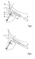
- Fig. 1
- eine schematische Darstellung der erfindungsgemäßen Einrichtung mit dem Trennmesser in der Trennposition,
- Fig. 2
- die Einrichtung nach Fig. 1 mit dem in Förderrichtung ausgelenkten Trennmesser in Trennposition und
- Fig. 3
- die Einrichtung nach Fig. 1 mit dem Trennmesser in der Parkposition.
Auf der dem Drehgelenk abgewandten Seite weist die Trennmesseraufnahme 5 eine Stützkurve 10 auf, die sich an der drehbar auf dem Träger 7 gelagerten Rolle 11 abstützt.
Der Träger 7 ist über eine von gestellfesten Führungen 13 aufgenommene Führungsstange 12 in Förderrichtung verschiebbar zum Maschinengestell gelagert. Die Führungsstange 12 trägt einen, eine Endlage vorgebenden Anschlag 15 und wird von einer Feder 14 gegen das Maschinengestell verspannt. Entlang des Verschiebeweges der Führungsstange 12 ist ein Schalter 16 angeordnet, der beim Verschieben der Führungsstange 12, das mit einem Auslenken des Trennmessers 1 einhergeht, von dem zu einer Schaltfahne verlängerten Anschlag 15 betätigt wird. Der Schalter 16 wirkt auf den Antrieb 9 des Trennmessers 1 derart, dass das Trennmesser 1 in die Parkposition verlagert wird, und/oder den Antrieb 9 der Druckmaschine derart, dass die Druckmaschine stillgesetzt wird.
Entlang des Förderweges ist ein Bogenleitblech 19 angeordnet, dass im Bereich des Trennmessers 1 ausgespart ist und die Bogen 18 im Bereich des Trennmessers 1 führt. Der Bogen 18 läuft an der Mantelfläche des bogenführenden Zylinders 4 mit, bis er das Bogenleitblech 19 erreicht. Mit der als Blasrohr ausgebildeten Blaseinrichtung 17 ist ein Blasluftstrom erzeugbar, der auf die dem bogenführenden Zylinder 4 abgewandte Seite der Bogen 18 gerichtet ist und die Bogen 18 führt bzw. auf dem Bogenleitblech 19 hält.
Die Bogen 18 werden von den Greifersystemen 3 des Fördersystems über das Trennmesser 1 geführt. Dabei werden von dem Trennmesser 1 die quer zur Schnittlinie die geschnittenen Bogen 18 miteinander verbindendenden Restfasern, die die Schneideinrichtung nicht vollständig getrennt hat, beginnend von der Vorderkante 18.1 der Bogen 18 zerschnitten. Der Bogen 18 läuft weiter am Mantel des bogenführenden Zylinders 4 mit, maximal bis zum Auflaufen auf das Bogenleitblech 19. Die Schnittlinie läuft dabei am Trennmesser 1 entlang. Die Restfasern im mittleren und hinteren Bereich der Bogen 18 werden getrennt.
- 1
- Trennmesser
- 2
- Übergabebereich
- 3
- Greifersysteme
- 4
- bogenführender Zylinder (Schneidtrommelmantel)
- 5
- Trennmesseraufnahme
- 6
- Nut
- 7
- Träger
- 8
- Gleitstein
- 9
- Antrieb (Pneumatikzylinder)
- 10
- Stützkurve
- 11
- Rolle
- 12
- Führungsstange
- 13
- Führungen
- 14
- Feder
- 15
- Anschlag
- 16
- Schalter
- 17
- Blaseinrichtung (Blasdüsen)
- 18
- Bogen
- 18.1
- Vorderkante
- 19
- Bogenleitblech
Claims (12)
- Einrichtung in einer Druckmaschine, die von einer Schneideinrichtung längs geschnittene, lediglich durch Restfasern miteinander verbundene Bogen (18) trennt, die in einem Übergabebereich (2) von einem bogenführenden Zylinder (4) an ein umlaufendes Fördersystem übergeben werden, das die Bogen (18) bis zu ihrer Freigabe über einem Auslegerstapel in einer Förderrichtung entlang eines Förderweges transportiert, umfassend ein Trennmesser (1) mit einer Schneide,
dadurch gekennzeichnet, dass
das Trennmesser (1) zwischen einer Parkposition, in der die Schneide außerhalb des Förderweges verläuft, und einer Trennposition, in der sich die Schneide in Förderrichtung unmittelbar nach dem Übergabebereich (2) in den Förderweg hinein erstreckt, verlagerbar ist. - Einrichtung in einer Druckmaschine nach Anspruch 1, dadurch gekennzeichnet, dass das Trennmesser (1) in der Trennposition in Förderrichtung auslenkbar gelagert ist.
- Einrichtung in einer Druckmaschine nach Anspruch 2, dadurch gekennzeichnet, dass die Trennposition des Trennmessers (1) in Förderrichtung durch einen Anschlag (15) und eine das Trennmesser (1) gegen den Anschlag (15) verspannende Feder (14) vorgegeben ist.
- Einrichtung in einer Druckmaschine nach Anspruch 1, dadurch gekennzeichnet, dass zur Verlagerung des Trennmessers (1) zwischen der Trennposition und der Parkposition ein Antrieb (9) vorgesehen ist.
- Einrichtung in einer Druckmaschine nach Anspruch 4, dadurch gekennzeichnet, dass der Antrieb (9) als Pneumatikzylinder ausgebildet ist.
- Einrichtung in einer Druckmaschine nach Anspruch 2 und 4, dadurch gekennzeichnet, dass ein Schalter (16) vorgesehen ist, der durch Auslenken des Trennmessers (1) in Förderrichtung betätigbar ist und mit dem auf das Trennmesser (1) wirkenden Antrieb (9) derart zusammenwirkt, dass bei Betätigung des Schalters (16) das Trennmesser (1) in die Parkposition verlagert wird.
- Einrichtung in einer Druckmaschine nach Anspruch 2 und 4, dadurch gekennzeichnet, dass ein Schalter (16) vorgesehen ist, der durch Auslenken des Trennmessers (1) in Förderrichtung betätigbar ist und mit einem Druckmaschinenantrieb derart zusammenwirkt, dass bei Betätigung des Schalters (16) die Druckmaschine stillgesetzt wird.
- Einrichtung in einer Druckmaschine nach Anspruch 1, dadurch gekennzeichnet, dass die Schneideinrichtung dem als Schneidtrommel ausgebildeten bogenführenden Zylinder (4) zugeordnet ist.
- Einrichtung in einer Druckmaschine nach Anspruch 1, dadurch gekennzeichnet, dass das Trennmesser (1) annähernd senkrecht zum Förderweg verschiebbar gelagert ist.
- Einrichtung in einer Druckmaschine nach einem der vorhergehenden Ansprüche, dadurch gekennzeichnet, dass ein sich längs des Förderweges erstreckendes, die Bogen (18) im Bereich des Trennmessers (1) führendes Bogenleitblech (19) vorgesehen ist.
- Einrichtung in einer Druckmaschine nach einem der vorhergehenden Ansprüche, dadurch gekennzeichnet, dass das Trennmesser (1) austauschbar in einer Trennmesseraufnahme (5) angeordnet ist.
- Einrichtung in einer Druckmaschine nach einem der vorhergehenden Ansprüche, dadurch gekennzeichnet, dass mit einer Blaseinrichtung (17) ein auf die dem bogenführenden Zylinder (4) abgewandten Seiten der Bogen (18) gerichteter Blasluftstrom, der die Bogen (18) im Bereich des Trennmessers (1) führt, erzeugbar ist.
Applications Claiming Priority (2)
| Application Number | Priority Date | Filing Date | Title |
|---|---|---|---|
| DE10332670 | 2003-07-18 | ||
| DE2003132670 DE10332670A1 (de) | 2003-07-18 | 2003-07-18 | Einrichtung zum Trennen von geschnittenen Bogen in einer Druckmaschine |
Publications (3)
| Publication Number | Publication Date |
|---|---|
| EP1498374A2 true EP1498374A2 (de) | 2005-01-19 |
| EP1498374A3 EP1498374A3 (de) | 2009-04-22 |
| EP1498374B1 EP1498374B1 (de) | 2010-04-21 |
Family
ID=33461984
Family Applications (1)
| Application Number | Title | Priority Date | Filing Date |
|---|---|---|---|
| EP20040016391 Expired - Lifetime EP1498374B1 (de) | 2003-07-18 | 2004-07-13 | Einrichtung zum Trennen von geschnittenen Bögen in einer Druckmaschine |
Country Status (2)
| Country | Link |
|---|---|
| EP (1) | EP1498374B1 (de) |
| DE (2) | DE10332670A1 (de) |
Cited By (3)
| Publication number | Priority date | Publication date | Assignee | Title |
|---|---|---|---|---|
| DE102008005775A1 (de) | 2008-01-24 | 2009-07-30 | Koenig & Bauer Aktiengesellschaft | Vorrichtung zum Längsschneiden von Druckbogen in einer Rotationsdruckmaschine |
| CN113370641A (zh) * | 2021-06-08 | 2021-09-10 | 安徽天翔高新特种包装材料集团有限公司 | 带有柔版印刷部件的墙纸生产设备 |
| CN116495549A (zh) * | 2023-04-28 | 2023-07-28 | 福强新材料(武汉)有限公司 | 矩形密封垫分切机 |
Families Citing this family (1)
| Publication number | Priority date | Publication date | Assignee | Title |
|---|---|---|---|---|
| DE102008001500B4 (de) * | 2008-04-30 | 2021-07-08 | manroland sheetfed GmbH | Schneideinrichtung für eine Bogendruckmaschine |
Citations (2)
| Publication number | Priority date | Publication date | Assignee | Title |
|---|---|---|---|---|
| DE19720742A1 (de) | 1997-05-17 | 1998-11-19 | Kba Planeta Ag | Einrichtung in Bogenauslegern |
| DE19842344A1 (de) | 1998-09-16 | 2000-04-06 | Roland Man Druckmasch | Verfahren zum Transport von Bogen und nach dem Verfahren arbeitende Bogenbearbeitungsmaschine |
Family Cites Families (7)
| Publication number | Priority date | Publication date | Assignee | Title |
|---|---|---|---|---|
| US2268111A (en) * | 1939-06-26 | 1941-12-30 | John A Davidson | Slitter and the like for sheet feeding presses |
| DE1215177B (de) * | 1961-01-28 | 1966-04-28 | Maschf Augsburg Nuernberg Ag | Kreismesser-Schneidvorrichtung zum Laengsschneiden von Bogen im Kettenableger einer Druckmaschine |
| DD81867A1 (de) * | 1970-07-03 | 1971-05-12 | Schneideinrichtung | |
| DE3318068A1 (de) * | 1983-05-18 | 1984-11-22 | M.A.N.- Roland Druckmaschinen AG, 6050 Offenbach | Bogendruckmaschine mit einrichtung zum laengsschneiden von druckboegen |
| FI266U1 (fi) * | 1992-05-07 | 1992-09-16 | Heinolan Newtec Oy | Kapningsanordning foer aemnesbana, saosom en pappersbana |
| DE4414908C2 (de) * | 1994-04-28 | 1998-03-12 | Roland Man Druckmasch | Verfahren und Vorrichtung zum partiellen Längsschneiden oder Längsperforieren von Bedruckstoffen |
| DE19500536C1 (de) * | 1995-01-11 | 1996-03-28 | Roland Man Druckmasch | Bogendruckmaschine mit einer Einrichtung zum Längsschneiden oder Perforieren von Druckbogen |
-
2003
- 2003-07-18 DE DE2003132670 patent/DE10332670A1/de not_active Withdrawn
-
2004
- 2004-07-13 EP EP20040016391 patent/EP1498374B1/de not_active Expired - Lifetime
- 2004-07-13 DE DE200450011064 patent/DE502004011064D1/de not_active Expired - Lifetime
Patent Citations (2)
| Publication number | Priority date | Publication date | Assignee | Title |
|---|---|---|---|---|
| DE19720742A1 (de) | 1997-05-17 | 1998-11-19 | Kba Planeta Ag | Einrichtung in Bogenauslegern |
| DE19842344A1 (de) | 1998-09-16 | 2000-04-06 | Roland Man Druckmasch | Verfahren zum Transport von Bogen und nach dem Verfahren arbeitende Bogenbearbeitungsmaschine |
Cited By (3)
| Publication number | Priority date | Publication date | Assignee | Title |
|---|---|---|---|---|
| DE102008005775A1 (de) | 2008-01-24 | 2009-07-30 | Koenig & Bauer Aktiengesellschaft | Vorrichtung zum Längsschneiden von Druckbogen in einer Rotationsdruckmaschine |
| CN113370641A (zh) * | 2021-06-08 | 2021-09-10 | 安徽天翔高新特种包装材料集团有限公司 | 带有柔版印刷部件的墙纸生产设备 |
| CN116495549A (zh) * | 2023-04-28 | 2023-07-28 | 福强新材料(武汉)有限公司 | 矩形密封垫分切机 |
Also Published As
| Publication number | Publication date |
|---|---|
| DE10332670A1 (de) | 2005-02-24 |
| EP1498374A3 (de) | 2009-04-22 |
| EP1498374B1 (de) | 2010-04-21 |
| DE502004011064D1 (de) | 2010-06-02 |
Similar Documents
| Publication | Publication Date | Title |
|---|---|---|
| DE2518373C2 (de) | Einrichtung zum Vergleichmässigen der gegenseitigen Abstände von in einem Schuppenstrom aufeinanderfolgenden Druckprodukten | |
| EP0986478A1 (de) | Verfahren zum quertrennen einer laufenden papierbahn | |
| EP0654349A1 (de) | Magazin für das automatisierte Wechseln von Druckplatten einer Druckmaschine | |
| DE19616047B4 (de) | Zusammentragmaschine | |
| EP0897890B1 (de) | Verfahren und Vorrichtung zur Erstellung eines gedrehten Produktstromes mit einem Eckengreifer | |
| DE3706058A1 (de) | Anleger fuer eine druckmaschine | |
| EP1939008B1 (de) | Sammelhefter mit variabler Kettenteilung | |
| EP2363364B1 (de) | Bogenleitvorrichtung, Fertigungssystem für Druckprodukte mit einer Bogenleitvorrichtung und Verfahren zum Herstellen von Druckprodukten | |
| EP0225994B1 (de) | Verfahren und Vorrichtung zum Abbremsen und Auslegen von in einer Druckmaschine bedruckten Bogen oder Bogenpaketen | |
| DE102012019051B4 (de) | Transportvorrichtung für Bogen mit obenliegender Blasluftkammer | |
| EP1498374B1 (de) | Einrichtung zum Trennen von geschnittenen Bögen in einer Druckmaschine | |
| DE102004007599A1 (de) | Bogen verarbeitende Maschine mit einem Bogenentroller | |
| DE10056018B4 (de) | Einrichtung zur Unterstützung der Bogenführung und Bogenablage | |
| DE7531302U (de) | Vorrichtung zum trennen und stapeln mehrerer aus einem kartonbogen o.dgl. gestanzter kartonzuschnitte | |
| DE19842344C2 (de) | Verfahren zum Transport von Bogen und nach dem Verfahren arbeitende Bogenbearbeitungsmaschine | |
| DE102008046125A1 (de) | Bogenverarbeitungsmaschine und Verfahren zum Ablegen von Bogen | |
| EP1498265B1 (de) | Einrichtung zum Trennen von geschnittenen Bogen im Ausleger einer Druckmaschine | |
| DE4316400C2 (de) | Einrichtung zur Entnahme aus einem Förderstrom ausgeschleuster Exemplare | |
| EP0409046A1 (de) | Bogenausleger für Druckmaschinen | |
| DE9411462U1 (de) | Blaseinrichtung zur Unterstützung der Bogenführung | |
| EP1745941B1 (de) | Dreischneider für den Beschnitt von Broschüren | |
| DE102008051581B4 (de) | Vorrichtung zum Abziehen einer Druckplatte vom Plattenzylinder einer Druckmaschine | |
| EP1110894B1 (de) | Verfahren und Vorrichtung zum Falzen von Materialbogen | |
| DE102010039504B4 (de) | Verarbeitungsmaschine mit einer Längstrenneinrichtung für Bogenmaterial | |
| DD225409A1 (de) | Einrichtung in bogenauslegern |
Legal Events
| Date | Code | Title | Description |
|---|---|---|---|
| PUAI | Public reference made under article 153(3) epc to a published international application that has entered the european phase |
Free format text: ORIGINAL CODE: 0009012 |
|
| AK | Designated contracting states |
Kind code of ref document: A2 Designated state(s): AT BE BG CH CY CZ DE DK EE ES FI FR GB GR HU IE IT LI LU MC NL PL PT RO SE SI SK TR |
|
| AX | Request for extension of the european patent |
Extension state: AL HR LT LV MK |
|
| PUAL | Search report despatched |
Free format text: ORIGINAL CODE: 0009013 |
|
| AK | Designated contracting states |
Kind code of ref document: A3 Designated state(s): AT BE BG CH CY CZ DE DK EE ES FI FR GB GR HU IE IT LI LU MC NL PL PT RO SE SI SK TR |
|
| AX | Request for extension of the european patent |
Extension state: AL HR LT LV MK |
|
| 17P | Request for examination filed |
Effective date: 20090420 |
|
| 17Q | First examination report despatched |
Effective date: 20090605 |
|
| GRAP | Despatch of communication of intention to grant a patent |
Free format text: ORIGINAL CODE: EPIDOSNIGR1 |
|
| GRAS | Grant fee paid |
Free format text: ORIGINAL CODE: EPIDOSNIGR3 |
|
| AKX | Designation fees paid |
Designated state(s): DE FR GB IT |
|
| GRAA | (expected) grant |
Free format text: ORIGINAL CODE: 0009210 |
|
| AK | Designated contracting states |
Kind code of ref document: B1 Designated state(s): DE FR GB IT |
|
| REG | Reference to a national code |
Ref country code: GB Ref legal event code: FG4D Free format text: NOT ENGLISH |
|
| REF | Corresponds to: |
Ref document number: 502004011064 Country of ref document: DE Date of ref document: 20100602 Kind code of ref document: P |
|
| PLBE | No opposition filed within time limit |
Free format text: ORIGINAL CODE: 0009261 |
|
| STAA | Information on the status of an ep patent application or granted ep patent |
Free format text: STATUS: NO OPPOSITION FILED WITHIN TIME LIMIT |
|
| 26N | No opposition filed |
Effective date: 20110124 |
|
| PGFP | Annual fee paid to national office [announced via postgrant information from national office to epo] |
Ref country code: DE Payment date: 20140812 Year of fee payment: 11 |
|
| PGFP | Annual fee paid to national office [announced via postgrant information from national office to epo] |
Ref country code: FR Payment date: 20140721 Year of fee payment: 11 Ref country code: GB Payment date: 20140721 Year of fee payment: 11 |
|
| PGFP | Annual fee paid to national office [announced via postgrant information from national office to epo] |
Ref country code: IT Payment date: 20140724 Year of fee payment: 11 |
|
| REG | Reference to a national code |
Ref country code: DE Ref legal event code: R119 Ref document number: 502004011064 Country of ref document: DE |
|
| GBPC | Gb: european patent ceased through non-payment of renewal fee |
Effective date: 20150713 |
|
| PG25 | Lapsed in a contracting state [announced via postgrant information from national office to epo] |
Ref country code: GB Free format text: LAPSE BECAUSE OF NON-PAYMENT OF DUE FEES Effective date: 20150713 Ref country code: IT Free format text: LAPSE BECAUSE OF NON-PAYMENT OF DUE FEES Effective date: 20150713 Ref country code: DE Free format text: LAPSE BECAUSE OF NON-PAYMENT OF DUE FEES Effective date: 20160202 |
|
| REG | Reference to a national code |
Ref country code: FR Ref legal event code: ST Effective date: 20160331 |
|
| PG25 | Lapsed in a contracting state [announced via postgrant information from national office to epo] |
Ref country code: FR Free format text: LAPSE BECAUSE OF NON-PAYMENT OF DUE FEES Effective date: 20150731 |