EP1498237B1 - Dispositif d'élagage de végétation - Google Patents
Dispositif d'élagage de végétation Download PDFInfo
- Publication number
- EP1498237B1 EP1498237B1 EP04254189A EP04254189A EP1498237B1 EP 1498237 B1 EP1498237 B1 EP 1498237B1 EP 04254189 A EP04254189 A EP 04254189A EP 04254189 A EP04254189 A EP 04254189A EP 1498237 B1 EP1498237 B1 EP 1498237B1
- Authority
- EP
- European Patent Office
- Prior art keywords
- cutting element
- pruning device
- vegetation pruning
- vegetation
- arms
- Prior art date
- Legal status (The legal status is an assumption and is not a legal conclusion. Google has not performed a legal analysis and makes no representation as to the accuracy of the status listed.)
- Not-in-force
Links
Images


Classifications
-
- A—HUMAN NECESSITIES
- A01—AGRICULTURE; FORESTRY; ANIMAL HUSBANDRY; HUNTING; TRAPPING; FISHING
- A01G—HORTICULTURE; CULTIVATION OF VEGETABLES, FLOWERS, RICE, FRUIT, VINES, HOPS OR SEAWEED; FORESTRY; WATERING
- A01G3/00—Cutting implements specially adapted for horticultural purposes; Delimbing standing trees
- A01G3/08—Other tools for pruning, branching or delimbing standing trees
- A01G3/085—Motor-driven saws for pruning or branching
- A01G3/086—Chain saws
-
- B—PERFORMING OPERATIONS; TRANSPORTING
- B27—WORKING OR PRESERVING WOOD OR SIMILAR MATERIAL; NAILING OR STAPLING MACHINES IN GENERAL
- B27B—SAWS FOR WOOD OR SIMILAR MATERIAL; COMPONENTS OR ACCESSORIES THEREFOR
- B27B17/00—Chain saws; Equipment therefor
- B27B17/0008—Means for carrying the chain saw, e.g. handles
-
- B—PERFORMING OPERATIONS; TRANSPORTING
- B27—WORKING OR PRESERVING WOOD OR SIMILAR MATERIAL; NAILING OR STAPLING MACHINES IN GENERAL
- B27B—SAWS FOR WOOD OR SIMILAR MATERIAL; COMPONENTS OR ACCESSORIES THEREFOR
- B27B17/00—Chain saws; Equipment therefor
- B27B17/0083—Attachments for guiding or supporting chain saws during operation
-
- B—PERFORMING OPERATIONS; TRANSPORTING
- B27—WORKING OR PRESERVING WOOD OR SIMILAR MATERIAL; NAILING OR STAPLING MACHINES IN GENERAL
- B27B—SAWS FOR WOOD OR SIMILAR MATERIAL; COMPONENTS OR ACCESSORIES THEREFOR
- B27B17/00—Chain saws; Equipment therefor
- B27B17/12—Lubricating devices specially designed for chain saws
-
- B—PERFORMING OPERATIONS; TRANSPORTING
- B27—WORKING OR PRESERVING WOOD OR SIMILAR MATERIAL; NAILING OR STAPLING MACHINES IN GENERAL
- B27B—SAWS FOR WOOD OR SIMILAR MATERIAL; COMPONENTS OR ACCESSORIES THEREFOR
- B27B17/00—Chain saws; Equipment therefor
- B27B17/14—Arrangements for stretching the chain saw
-
- B—PERFORMING OPERATIONS; TRANSPORTING
- B27—WORKING OR PRESERVING WOOD OR SIMILAR MATERIAL; NAILING OR STAPLING MACHINES IN GENERAL
- B27B—SAWS FOR WOOD OR SIMILAR MATERIAL; COMPONENTS OR ACCESSORIES THEREFOR
- B27B33/00—Sawing tools for saw mills, sawing machines, or sawing devices
- B27B33/14—Saw chains
-
- B—PERFORMING OPERATIONS; TRANSPORTING
- B27—WORKING OR PRESERVING WOOD OR SIMILAR MATERIAL; NAILING OR STAPLING MACHINES IN GENERAL
- B27G—ACCESSORY MACHINES OR APPARATUS FOR WORKING WOOD OR SIMILAR MATERIALS; TOOLS FOR WORKING WOOD OR SIMILAR MATERIALS; SAFETY DEVICES FOR WOOD WORKING MACHINES OR TOOLS
- B27G19/00—Safety guards or devices specially adapted for wood saws; Auxiliary devices facilitating proper operation of wood saws
- B27G19/003—Safety guards or devices specially adapted for wood saws; Auxiliary devices facilitating proper operation of wood saws for chain saws
Definitions
- the present invention relates to a vegetation pruning device and has particular, although not exclusive, relevance to such a device as would be used for gardening purposes.
- shears for pruning or cutting "light” vegetation such as grass or leaves or small twigs etc.
- Shears operate by pivoting a pair of blades located in parallel planes relative to each other so that shear forces are applied to vegetation placed in the angle between the blades, the cutting force being generated by manual force of the user, applied to handles attached to the blades.
- the size or thickness of vegetation which can be cut by shears is limited to the amount of manual force which can reasonably be applied to the handles by the average user.
- hedge trimmers At the other end of the scale there are hedge trimmers and the so-called chain saw used for "heavy" vegetation cutting such as trees (whether smaller branches or the entire tree).
- an object of the present invention to provide a vegetation pruning device which at least alleviates the above shortcomings by providing a novel form of tool which fits nicely in this gap. Provision of such a tool provides a compact and safe arrangement whereby pruning of the "heavier" vegetation is possible without the need to resort to the aggressive and particularly dangerous tool such as a chain saw.
- a known type of chain saw is disclosed in US 4294012 and has a guard pivotable relative to a blade of the chain saw and located in a plane parallel to the plane of the chain saw blade, to enable the blade to either be inserted beneath a log to be sawn, to reduce the tendency of the sawn piece of log to pinch the chain saw blade, or to grasp small branches to be sawn and force them into the chain saw.
- the chain saw has a first handle arranged on the chain saw body, and a second handle connected to the guard, so that the guard can be pivoted relative to the chain saw blade by pivoting the handles relative to each other.
- the handles of the chain saw of US 4294012 are arranged along axes generally perpendicular to each other, and perpendicular to the axis about which the guard pivots relative to the chain saw blade.
- a user's wrists face directions generally perpendicular to each other, which results in sidewards twisting torque being applied to the chain saw.
- This drawback is exacerbated when a gripping force is applied to the guard to grip a branch being sawn between the guard and the chain saw blade.
- the first handle of the arrangement of US 4294012 is generally in the same plane as the chain saw guard, whereas the second handle is spaced from the plane of the guard in the direction of the pivot axis.
- This also exacerbates the extent to which sideward twisting torque is applied to the chain saw when in use, which causes undesirable reduction in control of the chain saw.
- the guard of the arrangement of US 4294012 only extends along the lower side of the chain saw blade, and is arranged in a plane parallel to the chain saw blade. This causes the disadvantages that the extent to which the guard restricts access to the chain is limited, and the extent to which the chain saw can be of compact construction is also limited.
- the spacing between the plane of the guard and the plane of the chain saw blade results in undesirable twisting torque being applied to the chain saw when vegetation being sawn is gripped between the guard and the chain, which reduces the level of control the user has over the chain saw.
- US 6560879 discloses a chain saw in which a cutting chain is supported on a guide bar and driven around the guide bar by means of a drive sprocket located on the chain saw housing and is driven around an idler sprocket located on the guide bar.
- the guide bar is releasably held in position relative to the housing by means of cooperating friction surfaces on a locking plate mounted on the guide bar and a cover plate located between the guide bar and a cover assembly, such that when the cooperating friction surfaces are in their released condition, a tensioner pin is caused by a cam biased by means of a torsion spring urges the guide bar away from the housing so that the drive and idler sprockets are urged apart to keep the chain taut.
- a vegetation pruning device including: a pair of arms adapted to pivot relative to each other about an axis to adjust the angle between said arms and having at least one respective handle portion adapted to be gripped by a user; a motor having a rotary output drive; an endless flexible cutting element mounted to a first said arm and adapted to be driven relative to said arm by means of said rotary output drive to cut vegetation presented thereto; at least one first guard member mounted to said first arm for restricting access to said cutting element; and at least one second guard member mounted to a second said arm for restricting access to said cutting element at least when the angle between said arms is at its minimum permitted value, wherein said cutting element is arranged substantially in a plane passing through at least one said first guard member and at least one said second guard member.
- this provides the advantage that access to the cutting element can be much more effectively restricted than in the arrangement of US 4294012, while at the same time enabling the pruning device to be of more compact construction. Furthermore, by having the cutting element located in a plane passing through at least one second guard member (i.e. mounted on the second arm), this provides the advantage that forces are applied to vegetation being gripped between the arms substantially in a single plane, which minimises the extent to which unwanted twisting torque is applied to the pruning device when gripping vegetation between the arms.
- the arms are adapted to be gripped by a user at a pair of said handle portions oriented substantially symmetrically relative to each other about said axis.
- the arms are preferably adapted to be gripped by a user at a pair of said handle portions arranged in a plane substantially perpendicular to said axis. This provides the advantage of further minimising the extent to which undesirable sidewards twisting torque is applied to the pruning device when it is used to grip vegetation between the cutting element and the second arm.
- the motor may be mounted to said first arm.
- the pruning device may further comprise at least one power supply for powering said motor, wherein at least one said power supply is mounted to said first arm on a side therefore opposite to said motor.
- the arms are pivotable between a first position allowing access to said cutting element, and a second position in which the cutting element is substantially inaccessible.
- This feature enhances the safety of the device when the shear arrangement is in its closed position. It prevents the user accidentally putting their fingers or hands in contact with the cutting element - something which is desirable to avoid.
- the pruning device may further comprise first biasing means for biasing said arms towards said second position.
- At least one first and at least one second guard member may be adapted to engage each other at least adjacent respective ends thereof remote from said axis when said arms are in said second position.
- the pruning device may further comprise first locking means for releasably locking said arms in said second position.
- At least one second guard member may be moveable between a first position allowing access to said cutting element and a second position preventing access to said cutting element.
- the pruning device may further comprise second biasing means for biasing at least one said second guard member towards said second position.
- At least one said moveable second guard member may be moveable to said first position only when said arms are in said second position.
- At least one first and/or said second guard member may be resiliently biased towards the cutting element and movable away therefrom under application of force.
- At least one first and/or second guard member may comprise first vegetation restraining means having a series of indentations and or projections disposed towards said cutting element to provide points of restraint or retention of said vegetation thereagainst.
- At least one first and/or second guard member may be associated with said cutting element so as to be displaceable away from said cutting element by said vegetation through which said cutting element has cut.
- the pruning device may further comprise a third guard member for preventing access to said cutting element at an end therefore remote from said axis.
- the third guard member may be adapted to lock said first and second guard members together when said arms are in said second position.
- the second arm may comprise second vegetation restraining means for restraining vegetation inserted between said pair of arms from displacement when engaged with said cutting element.
- the second vegetation restraining means may comprise a series of indentations and or projections disposed towards said cutting element to provide points of restraint or retention of said vegetation thereagainst.
- the series of projections may comprise a plurality of teeth inclined and facing towards said cutting element.
- the second arm may comprise a substantially parallel pair of side walls defining a channel therebetween for at least partially receiving said cutting element as the cutting element is pivotally displaced towards said second arm.
- the pruning device may further comprise at least one stop member to limit pivotal displacement of said arms towards one another for restraining said cutting element at a predetermined pivotal position relative to said second arm so as to remain received within said channel.
- the channel may comprise an inner surface extending between said substantially parallel side walls defining a dust/debris conveying path communicating with a dust/debris extraction aperture.
- the substantially parallel pair of side walls may be profiled to allow at least part of said cutting element to pass completely through said channel as said cutting element is pivotally displaced towards said other of said pair of arms.
- the side walls may have a V-shaped profile for receiving and supporting in an inner apex thereof vegetation to be cut.
- V-shaped profile permits accurate holding of vegetation of different diameters at a predetermined, usually central, position relative to the cutting element.
- the cutting element may rotate within a first plane and the arms of the pair of arms each include a surface which extends either side of this first plane.
- the motor rotary output drive may include a toothed drive wheel.
- the cutting element may comprise a chain.
- the teeth of the toothed wheel may fit between the links of the chain in use to provide motive force to the chain.
- the chain may further include a plurality of barbs to assist in vegetation pruning.
- the motor may have an output gear adapted to rotate about an axis substantially parallel or substantially perpendicular to the axis of rotation of said rotary output drive.
- the cutting element may be mounted upon a support member and arranged for rotation thereabout under the influence of the rotary output drive.
- the support member may include a driven and a drive wheel around which the cutting element moves as the drive wheel rotates.
- the pruning device may further comprise an actuator for controlling operation of the motor.
- the actuator may be a variable speed-controller for governing the output speed of the motor.
- the actuator may comprise at least one resiliently biased switch member mounted on each of the two arm members, wherein said actuator is restrained from operating said motor unless at least one said switch member on each arm is operated.
- Such resiliently biased switch member may provide either mechanical or electrical restraint of the actuator when in a non-operated position.
- the pruning device may comprise a self adjusting tensioning device to allow automatic adjustment of the support member.
- Adjustment of said support member may effect tensioning of said cutting element.
- the self adjusting tensioning device may comprise adjustable restraint means for releasably securing said support member relative to said pruning device together with a rigid support block rigidly secured to one of said pair of pivotally coupled arms on which said support member is mounted, said block having a resiliently biased adjustment member disposed between said support block and said support member to exert a displacement force on said support member away from said support block when said restraint member is in a released position.
- the biasing member may comprise a spring biased plunger having a first ratchet member and said support block having a second ratchet member whereby engagement between said first and second ratchet members prevents displacement of said plunger towards said support block.
- the pruning device may further comprise a lubricating device for depositing lubricating material on said cutting element.
- the lubricating device may include a reservoir for lubricating material located within a second said arm.
- the lubricating device may be adapted to deposit a predetermined amount of lubricating material on said cutting element in response to opening of said arms relative to each other and/or opening and closing of said arms relative to each other.
- the motor may be an electric motor adapted to be switched so as to effect braking of said cutting element.
- a self adjusting tensioning device for tensioning an endless chain extending between two wheels, comprising a support member on which is mounted one of said two wheels and a support block restrained from displacement relative to said other of said two wheels, wherein said support block has operatively associated therewith an adjustable restraint means for releasably securing said support member relative to said support block, and which device further comprising at least one adjustment member disposed between said support block and support member and resiliently biased by means of at least one compression spring to exert a displacement force on said support member in a direction away from said support block when said restraint member is in a released position.
- the tensioning device may further comprise a locking system between said resiliently biased adjustment member and said support block for restraining said adjustment member from displacement towards said support block.
- the locking system may comprise one of a series of ratchet teeth or a ratchet pawl disposed on said support block and the other of said series of ratchet teeth or a ratchet pawl disposed on said adjustment member, whereby the ratchet pawl engages said ratchet teeth to restrain displacement of said adjustment member towards said support block.
- a chain system comprising an endless chain, two wheels about which said chain is supported and a self adjusting tensioning device as defined above.
- a lubricating device for a powered cutting apparatus having a pair of arms adapted to pivot relative to each other about an axis to adjust the angle between said arms and having at least one respective handle portion adapted to be gripped by a user; a motor having a rotary output drive; and a cutting element mounted to a first said arm and adapted to be driven relative to said arm by means of said rotary output drive to cut vegetation presented thereto, the device comprising depositing means for depositing a predetermined amount of lubricating material onto said cutting element in response to opening of said arms relative to each other and/or opening and closing of said arms relative to each other.
- the lubricating device may further comprise a reservoir for lubricating material adapted to be located within one of said arms.
- the depositing means may be adapted to adjust said predetermined amount in response to the speed at which said cutting element is driven.
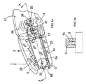
- a vegetation pruning device shown generally as 2 is shown.
- the pruning device comprises a pair of pivotally coupled arms 4 and 6 which are arranged generally in the same plane as each other.
- the upper arm 6 of the pair of arms 4, 6 comprises a composite structure formed from a cutting element 8 and an outer portion 10 biased towards the cutting element 8.
- a pivot point 12 in this embodiment an appropriate through bolt, articulates the first arm 4 of the pair of arms to the second arm 6 of the pair of arms so that the arms 4, 6 can be "open” and "closed” by appropriate relative movement of respective handles 14 and 16 of the arms.
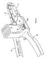
- FIG 2 it can be seen that a user may move the handles 14, 16 apart from one another (as indicated by arrow A) such that the arms 4, 6 also move apart from one another to the "open” position via the pivot point 12.
- opening the arms 4, 6 exposes the cutting element 8 such that vegetation for pruning may be introduced into the space between the arm 4 and cutting element 8.
- the cutting element 8 is generally shielded such that it is substantially inaccessible. This will become more understandable from the description below and particularly with reference to Fig 6.
- the cutting element 8 in this example a linked chain, passes over a support member, in this example a longitudinally extending chain bar 20.
- the chain 8 and chain bar 20 are arranged generally in the same plane as arms 4, 6.
- a longitudinal section taken through the chain 8 is shown in figure 7.
- the chain 8 comprises a plurality of links 22 which serve to interconnect sets of pairs of chain elements 24.
- the construction of the linked chain 8, in this manner, therefore, is conventional.
- Such a style of chain is used, for example, in chain saws for cutting trees and also on bicycles and motorbikes for providing motive force.
- FIG 3 Although not essential to the operation of the invention, are a plurality of barbs 26 coupled to the chain 8 used to assist in the cutting operation of the chain 8. It will be apparent to those skilled in the art that a conventional chain saw uses a linked chain with such barbs attached thereto. The purpose of the barbs 26 is to provide the cutting or slicing action of the chain in the vegetation to which it is presented.
- This chain 8 and chain bar 8 are similar to those employed in a conventional chain saw but, for the purpose of understanding the present invention, simply represent a powered cutting element.
- the arm 4, and the outer portion 10 of arm 6 includes side cover portions - respectively 4a, 6a and 4b, 6b - which serve, when the arms 4, 6 are in the "closed" position (in Figure 1), to at least partially encapsulate or surround the chain 8.
- the cover portion 6 comprises two substantially parallel side plate members (6a and 6b) having a space therebetween slightly greater than the maximum width of the chain and/or chain bar 20.
- each of the plates 6a and 6b are interconnected by a substantially perpendicular outer plate member (not shown) such that this arm portion 6, in cross section, presents a substantially U-shaped profile into which the chain (or powered cutting element) may be at least partially accommodated.
- the front end of this arm 6 is further curved so as to partially enclose the front end of the curved end of the cutting element as shown in Figure 1a.
- the arms 4, 6 can abut each other at their front ends in the closed position to completely restrict access to the front end of the cutting element 8. This significantly improves the safety of the apparatus, since accidents can result from inadvertent contact between the front end of the cutting element 8 with a workpiece or the ground, causing loss of control over the apparatus, or the flex supplying electric power to motor 36 can be inadvertently cut by passing into the gap between the arms 4, 6.
- a so-called nose guard (not shown) can be provided which restricts access to the front end of the cutting element 8. This can abut or enclose the front ends of arms 4, 6 when in their closed position to also prevent opening of the arms 4, 6 relative to each other.
- the proposed arm member 4 is again provided with a substantially U-shaped cross sectional profile (Figure 1b) into which at least part of the chain 8 may be accommodated (as indicated in hashed lines in Figure 1b).
- the arm members 4 and 6 serve to at least partially encompass the powered cutting element (chain 8).
- Both arms 4 and 6 are provided with curved front end portions to also partially enclose the front curved end of the cutting element.
- each of the cover portions 4a, 4b and 6a, 6b of their respective arms 4, 6 extend in a direction parallel with the plane ABCD, yet each of these extensions are arranged to be laterally offset both from the plane in which the chain 8 rotates and physically from the chain 8 itself, then access to the chain 8 by user from a direction perpendicular to this plane ABCD is not possible when the arms 4, 6 are in a closed position.
- the arm members 14 and 16 are designed so that when brought into the closed configuration as shown in Figure 1 the handle portions will engage one another to define a limited end stop to the pivoted closed position ( Figure 1).
- the arm member 16 is provided with a motor housing 17 (to be described below) against which an inner portion 19 of the upper handle 14 (the term inner used to indicate proximate pivot axis 12) which engages to define this end stop position ( Figure 1).
- This defined end stop position causes the side cover portions 4a and 4b of the arm 4 to partially enclose the blade but retain the arm portion 4 in a position whereby its inner face 4c (Figure 1b) is restrained from engaging with the blade 8 as shown.
- the arm member 4 whilst able to partially enclose the cutting element is restrained from engagement therewith when in an enclosed configuration.
- the upper arm 6 is pivotally biased to the position substantially shown in Figures 1, 1a and 2 so that it will partially enclose the cutting element or chain 8 but has a stop position as shown which prevents it from being displaced into engagement with such cutting element, again allowing the cutting element to be partially enclosed thereby but is restrained from interference with such cutting element operation.
- the arm 4 has a plurality of indentations or projections thereon, in this example projecting teeth 28, which are employed in use of the pruning device, to restrain vegetation being cut by the chain 8 in a largely immovable position relative to the arms 4, 6 and the cutting element 8.
- teeth 28 which are employed in use of the pruning device, to restrain vegetation being cut by the chain 8 in a largely immovable position relative to the arms 4, 6 and the cutting element 8.
- the purpose of the teeth 28, therefore, is to achieve such function.
- the teeth 28 could also be formed on the arms 6 in addition or alternatively to that of the arm 4.
- any suitable shape or profile of such indentations or projections which achieve the holding the vegetation steady relative to the cutting element are equally efficacious.
- the direction of rotation of the chain 8 is indicated by the arrows on the chain bar 20.
- the specific use of the saw tooth teeth 28 is such that rotation of chain 8 will cause it to engage with any workpiece placed between it and the jaws 4 whereby the cutting action will attempt to displace the branch or workpiece in a direction towards the pivot axis 12 which will, in practice, serve to drive such workpiece or branch into positive engagement with the teeth 28 therefore enhancing the gripping effect resultant from use of such teeth 28.
- teeth are employed on the arm member 6 then it is preferred such saw teeth will be inclined in an opposite direction to that of arm 4 so as to again cause any workpiece being cut to be forced into positive retaining engagement therewith in a similar manner to employment of the teeth 28.
- the proximal end (that is the one remote from the plane ABCD in figure 3) of the chain bar 20 includes a drive wheel or sprocket 30 (shown in Fig 1a and Fig 6 but not visible in the other figures) which engages and drives the chain 8 in a conventional manner.
- the distal end of the chain bar 20 includes a driven wheel or sprocket 32 (again, shown in Fig 1a and Fig 6 but not visible in the other figures) to allow rotation of the chain 8 around the chain bar 20.
- the chain 8 when driven by the drive sprocket 30, therefore, rotates in a continuous loop about the external periphery of the chain bar 20.
- the drive sprocket 30 is coupled to an output shaft 34 of an electric motor 36.
- the motor 36 provides a direct rotary output for the output shaft 34, although those skilled in the art will appreciate that, dependent upon the conditions of use of the pruning device, a gearbox (not shown) between the motor 36 and the drive sprocket 30 may be useful in order to adjust the amount of torque and/or the rotational speed exhibited by the chain 8 as it is being driven. In this manner, the cutting element operates as a conventional cutting element of a chain saw.
- Power for the motor 36 is provided in conventional manner by power supply cable 38 which will be coupled to a source of mains power or the like. (Alternatively, albeit not shown, power could be supplied by a battery or petrol engine).
- the motor 36 is powered by a rechargeable battery, which is arranged on the housing of the apparatus on the opposite side to the motor 36. This allows a particularly ergonomic arrangement in which the weight of the rechargeable battery balances that of the motor 36 so that the centre of gravity of the apparatus is as near as possible to the central plane of the apparatus. Operation of the motor 36 is dependent upon actuation of a trigger switch 40 by the user of the device 2.
- the trigger switch 40 is conveniently mounted upon one of the handles, in this example, handle 14.
- a secondary failsafe mechanism is illustrated by a secondary displaceable switch member 41 which again is readily accessible via a users fingers when gripping the handle 16.
- the use of dual switching mechanisms are conventional within many forms of power tools and their specific operation need not be described in any great detail here. However, their operation may be electrical or a combination of electrical mechanical mechanisms. For example operation of the motor will be prevented unless both switch elements 41 are displaced from an unactuated to an actuated position. In this manner the failsafe mechanism may simply comprise an electrical connection to the motor requiring a dual electrical input or may in fact provide some form of mechanical stop mechanism preventing electrical connection between the switch member 41 and the motor. A particular advantage in this invention will be determined that should the users grip on either handle be released then operation of the motor is immediately stopped.
- the trigger switch 40 in this embodiment not only controls actuation of the motor 36 but, dependent upon the amount of pressure applied thereto by user, dictates the speed of output of the motor 36. Such switches are readily available in the art.
- the safety of the pruning device can be further enhanced by having a braking arrangement for bringing the chain 8 to a halt as quickly as possible when power to the motor 36 is interrupted.
- a braking arrangement for bringing the chain 8 to a halt as quickly as possible when power to the motor 36 is interrupted.
- One way of achieving this is to arrange for the motor 36 to be short circuited when the switch 40 is released, so that the motor 36 acts as an electromagnetic brake.
- an oil reservoir 42 mounted adjacent the drive sprocket 30 and able to dribble lubricating oil onto the drive sprocket 30 during use of the motor 36.
- the lubrication mechanism can have a lubrication reservoir (not shown) arranged inside the lighter handle 14, as a result of which the apparatus is of compact construction, and the weight of the apparatus is balanced as evenly as possible.
- the lubricating mechanism can be arranged to dispense a fixed amount of lubricant in response to opening of the handles 14, 16 relative to each other, or in response to opening and then closing of the handles 14, 16 relative to each other.
- the lubricating mechanism can take higher levels of heating of the chain 8 into account by controlling the amount of lubricant dispensed in dependence upon the speed at which motor 36 is driven, so that more lubricant is dispensed at higher operating speeds of the motor 36.
- the chain tensioning mechanism employed in this specific embodiment is again one conventionally employed in the art of chain saws.
- the chain bar 20 (as is shown in Figure 1a) is securely mounted to the arm member 16 in the region of the motor housing 17 by an appropriate threaded bolt member (not shown).
- Such a threaded bolt member will have a first engaging face against which one side of the chain bar 20 is received and a second threaded nut member is then rotatably received on such bolt so as to compress the chain bar 20 therebetween. Operation of this nut or bolt can be achieved in a number of conventional manners but will usually employ an external sprocket member which can be manually rotated as appropriate.
- the chain bar 20 may then slideably displaced about this bolt member in a direction away from the pivot axis (12) of the pruning device by firstly loosening the nut member of the nut and bolt restraining mechanism and manually displacing the blade in a direction away from such pivot axis 12 effectively increasing the distance between the sprocket 32 and the sprocket 30 causing the tightening of the chain thereabout. Once appropriate tightening has been achieved the chain bar 20 is fixed into the new position by appropriate retightening of the nut and bolt member.
- This chain tension device is conventional for chain saws.
- the large cylindrical object 44 in the drawings is representative of vegetation to be pruned and, in this example, is meant to represent a section of a branch or a bush or the like.
- the arms 4, 6 are in the "open" position ( Figure 2) and the branch 44 is placed between the lower surface of the chain 8 adjacent the teeth 28 of arm 4, then the user will close the handles 14, 16 of the device until such time as the branch 44 contacts the lower surface of the chain 8 with its upper portion 44a and the teeth 28 of the arm 4 with its lower portion 44b.
- the trigger 40 As the user squeezes the trigger 40, the chain 8 is caused to rotate and the barbs 26 formed thereon will cut into and through the branch 44 in known manner.
- this outer portion 10 causes this portion 10 to move back into position shown in Figure 1 effectively providing its function as a chain guard.
- this chain guard is limited in its pivotal displacement so as not to be brought into engagement with the chain but to partially encompass it as shown in Figure 1a. This provides for a variable cutting depth irrespective of the depth of the chain bar 20.
- the device is provided with an appropriate dust or chip extraction aperture 100.
- the cutting operation of the chain 8 causes wood chippings and sawdust to be drawn towards the motor housing 17 and sprocket 30.
- Such movement is further enhanced by the formation of the U-shaped channel formed in arm member 4.
- a lower portion of the motor housing 17 is provided with an appropriate internal channel and external aperture 100 so that any sawdust or wood chippings drawn into the motor housing are simply extracted so as to fall out of this aperture whereby the speed of rotation of the chain will create an appropriate airflow serving to drive the wood chippings out of the tool.
- One of the major benefits of the current invention is the ability to provide a means of rigidly securing the branch or workpiece 44 in close proximity with the blade during the cutting operation.
- a further enhancement provides that the cutting element is partially encompassed so as to prevent inadvertent access thereto providing an enhanced safety feature for the operator.
- the invention can be further modified so that operation of the cutting element of the embodiment in Figures 1 to 5 is prevented in the absence of an article to be cut being placed between the cutting element and the jaw 4. This could be achieved by providing an appropriate sensing mechanism registering the presence of a branch between such cutting element 8.
- An example would be the provision of a further limited pivot action of the lower arm 4 which would be biased to the position conventionally shown in Figures 1 to 5.
- the cutting element 8 and the outer portion 10 of the arm 6 biased towards the cutting element 8 together comprise one arm 6 of the pair of arms 4, 6, it will be appreciated that these may be formed as separate elements.
- the other arm could actually comprise the chain bar 20 and its associated chain 8.
- the feature which is labelled 10 in the diagrams would not actually formed part of the other arm of the pair but would be a pivoting spring biased portion formed as a separate element. This distinction is not germane to the present invention, however.
- FIG. 8 there is a shown an alternative pruning device 2" (identical to pruning device 2 of Figure 1 with the exception of this chain tensioning device) having such a modified blade tensioning device shown generally by arrows 450.
- the cutting element comprises a chain 458 mounted on an appropriate support member (or chain bar) 460 for such chain 458 to extend between a first driven wheel or sprocket member 462 and a driven (or sprocket) wheel member 464
- use of the cutting chain 458 will incur considerable vibration, often effecting displacement of the support member 460 thus causing the chain to loosen.
- the support member 460 is adjustable so as to allow the chain to be retensioned as appropriate.
- This device 450 comprises a primary mounting block 466 securely mounted to the motor housing 417 and hence handle portion 416 so as to be effectively integral therewith.
- a steel compression plate 468 which is adjustable relative to and away from the mounting member 466 (as indicated by arrow 500) so as to effectively compress or release an internal end portion 470 of the support member 460, as schematically illustrated in Figure 8.
- the inner portion 470 of the support member 460 has a substantially rectangular rebate 461 allowing it to pass over an appropriate screw threaded member (not shown) upon which the compression plate 468 is mounted whereby a conventional wing nut (471) or other rotatable member (eg.
- a rotatable knob can then be used to adjust the compression plate towards or away from the mounting member 466 so as to compress and hold, or alternatively, release the support member 460 disposed between such plate 468 and block 466.
- this compression plate 468 is a greater size than rebate 461 to allow positive engagement of the plate 468 with the support member 460.
- the device 450 is further provided with an internal elongate channel 472 slideably accommodating a plunger 474 which is spring loaded via an appropriate coil spring 476 disposed between an internal end of the channel 472 and the plunger 474 as shown.
- the channel 472 is substantially square in cross section so as to retain the plunger in a desired displaceable orientation relative to the support member 460 as will be described below.
- the plunger is further provided with a series of ratchet teeth 476 inclined in a direction away from the mounting block 466 as shown.
- An appropriate non-return ratchet pawl 478 is then rigidly connect to the mounting member 466 so as to engage with the ratchet teeth 476 to prevent a return of the ratchet member 476 back into the mounting member 466 once displaced there out of by the spring member 476.
- this non-return ratchet pawl will be provided with an appropriate adjustment means which allows it to be displaced out of engagement with the ratchet teeth when the self-adjusting device is to be released to allow removal of the chain and necessary reduction in tension thereof to allow such removal.
- the support member 460 and the self-adjusting device 450 will be constructed as shown in Figure 8 with an outer end surface 480 of the plunger 474 in abutment with an internal surface 482 of the rebate 461 of the support member 460 as shown in Figure 8.
- the support member 460 When the compression plate 468 is in a released position, disposed away from the block 466, the support member 460 is no longer frictionally restrained against the mounting block 466, whereby the inherent resilient biasing of the coil spring 476 (which is set at between 2.2 kg (5 lbs) and 4.4 kg (10 lbs) pressure in a normal embodiment but could be anywhere between 2.2 kg (5 lbs) and 13.6 kg (30 lbs) of pressure) exerts a biasing force on the plunger 480 which is exerted against the internal surface 482 of rebate 461 so as to effect adjustment of the support member away from the support blocking a direction as shown by arrow 490 in Figure 8.
- the coil spring 476 which is set at between 2.2 kg (5 lbs) and 4.4 kg (10 lbs) pressure in a normal embodiment but could be anywhere between 2.2 kg (5 lbs) and 13.6 kg (30 lbs) of pressure
- the amount of displacement effected on the support member 460 by such biasing force is limited by the size of the chain member 458 but in this released configuration the self-adjusting device 450 serves to apply sufficient force to the support member 460 to effect appropriate tensioning to the chain 458 as required.
- the compression plate 468 can then be adjusted so as to clamp the support member 460 against the mounting member 466 to hold it in the self-adjusted, tensioned configuration.
- the non-return ratchet pawl 478 will assist in maintaining the plunger in this appropriate position.
- this specific embodiment provides an enhanced and simplified means of self-adjusting tensioning of a chain about a support member which simply allows loosening of the appropriate wing-nut on the compression plate 468 to effect appropriate self-adjustment of the chain tension.
- this self adjusting blade tensioning device 450 effects relative displacement between the two support wheels 464 and 462 as shown. This is achieved by mounting the driveable support wheel 464 on the support member 460 and securing the tensioning device 450 so as to be immovably displaced relative to the driven support wheel 462.
- this specific feature of self-adjusting blade tensioning device is not limited to use with a shear arrangement of the embodiments of Figures 1 to 7 but is equally applicable to any device utilising a rotatable chain where a minimum tensioning of the chain is required to be maintained and regularly adjusted, for example, conventional chainsaws or even bicycles.
- a wheel-nut is envisaged being mounted on a conventional screw threaded member to effect adjustment of the compression plate 468
- alternative means of adjustment of this compression plate 468 to and away from the mounting block 466 is readily envisaged and could simply be a conventional nut mounted on a screw threaded member or even a hydraulic compression arrangement.
- the arms 4, 6 can be arranged to control access to chain 8 to enhance the safety of the apparatus, for example by biasing the arms 4, 6 towards their closed position by means of one or more springs, and/or by having an openable guard on one of the arms 4, 6 to allow access to the chain 8 to enable the chain 8 to be replaced when it becomes worn.
- An interlock arrangement can prevent the guard from being opened when the motor 36 is actuated and/or when the arms 4, 6 are in their open position relative to each other offering access to the cutting element 8, and can prevent the motor from being actuated when the guard is open.
- the cutting element can be driven in a number of ways, for example by means of motor 36 having an output shaft arranged generally parallel to the axis of rotation of sprocket wheels driving the cutting element, or generally perpendicular to such axes, rotation of the output shaft of motor 36 driving one of the sprockets by means of one of more conical gears, or a gear plate rotated about an axis perpendicular to the axis of the output shaft and having gear teeth on its end face.
- One or more of the arms 4, 6 can also be arranged to have cutting edges on the face thereof facing away from the cutting element 8, so that the cutting edges can be used to effect manual cutting of vegetation by means of opening of the arms 4, 6 relative to each other.
Claims (44)
- Un dispositif d'élagage de végétation (2) comprenant :une paire de bras (4, 6), adaptée pour pivoter par rapport à chaque autre autour d'un axe, afin d'ajuster l'angle entre lesdits bras et d'avoir au moins une partie de poignée (14, 16) respective, adaptée pour être saisie par un utilisateur ;un moteur (36) ayant un arbre de sortie rotatif (34) ;un élément de coupe (8) flexible, sans fin, monté sur un dit premier bras (6) et adapté pour être entraîné par rapport audit bras, au moyen dudit entraînement de sortie rotatif, pour couper de la végétation (44) lui étant présentée ;au moins un premier organe de garde, monté sur ledit premier bras (6), pour limiter l'accès audit élément de coupe (8) ; etau moins un deuxième élément de garde, monté sur un dit deuxième bras (4), pour limiter l'accès audit élément de coupe, au moins lorsque l'angle entre lesdits bras est à sa valeur minimale autorisée ;caractérisé en ce que ledit élément de coupe (8) est agencé sensiblement dans un plan (A, B, C, D) passant par au moins un dit premier élément de garde et au moins un dit deuxième élément de garde.
- Un dispositif d'élagage de végétation selon la revendication 1, dans lequel lesdits bras (4, 6) sont adaptés pour être saisis par un utilisateur à une paire desdites parties de poignée (14, 16), orientées sensiblement symétriquement par rapport à chaque autre autour dudit axe.
- Un dispositif d'élagage de végétation selon la revendication 1 ou 2, dans lequel les bras (4, 6) sont adaptés pour être saisis par un utilisateur à une paire desdites parties de poignée (14, 16), agencées dans un plan (A, B, C, D) sensiblement perpendiculaire audit axe.
- Un dispositif d'élagage de végétation selon l'une quelconque des revendications précédentes, dans lequel ledit moteur (36) est monté sur ledit premier bras (6).
- Un dispositif d'élagage de végétation selon la revendication 4, comprenant en outre au moins une alimentation en énergie pour actionner ledit moteur (36), dans lequel au moins une dite alimentation en énergie est montée sur ledit premier bras (6), sur un côté de celui-ci, opposé audit moteur.
- Un dispositif d'élagage de végétation selon l'une quelconque des revendications précédentes, dans lequel les bras (4, 6) sont susceptibles de pivoter entre une première position, permettant un accès audit élément de coupe (8), et une deuxième position, à laquelle l'élément de coupe est sensiblement inaccessible.
- Un dispositif d'élagage de végétation selon la revendication 6, comprenant en outre des premiers moyens de sollicitation, pour solliciter lesdits bras vers ladite deuxième position.
- Un dispositif d'élagage de végétation selon la revendication 6 ou 7, dans lequel au moins un dit premier et au moins un dit deuxième élément de garde sont adaptés pour se mettre en prise ensemble à au moins des extrémités respectives adjacentes de ceux-ci, distantes dudit axe lorsque lesdits bras (4, 6) se trouvent à ladite deuxième position.
- Un dispositif d'élagage de végétation selon l'une quelconque des revendications 6 à 8, comprenant en outre des premiers moyens de verrouillage, pour verrouiller de façon désolidarisable lesdits bras à ladite deuxième position.
- Un dispositif d'élagage de végétation selon l'une quelconque des revendications précédentes, dans lequel au moins un dit deuxième élément de garde est déplaçable, entre une première position, permettant l'accès audit élément de coupe (8), et une deuxième position, empêchant l'accès audit élément de coupe.
- Un dispositif d'élagage de végétation selon la revendication 10, comprenant en outre des deuxièmes moyens de sollicitation, pour solliciter au moins un dit deuxième élément de garde déplaçable vers ladite deuxième position.
- Un dispositif d'élagage de végétation selon la revendication 10 ou 11, dans lequel au moins ledit deuxième élément de garde déplaçable est déplaçable vers ladite première position, uniquement lorsque lesdits bras (4, 6) se trouve à ladite deuxième position.
- Un dispositif d'élagage de végétation selon l'une quelconque des revendications précédentes, dans lequel au moins un dit premier et/ou un dit deuxième élément de garde est/sont sollicité(s) élastiquement vers l'élément de coupe (8) et est/sont déplaçable(s) en s'écartant de celui-ci, sous l'application d'une force.
- Un dispositif d'élagage de végétation selon la revendication 13, dans lequel au moins un dit premier élément de garde et/ou un dit deuxième élément de garde comprend (comprennent) des premiers moyens de retenue de végétation (28) comprenant une série de dents et/ou de saillies disposées vers ledit élément de coupe (8), pour fournir des points de restriction ou de rétention de ladite végétation contre elle.
- Un dispositif d'élagage de végétation selon la revendication 13 ou la revendication 14, dans lequel au moins un dit premier et/ou un dit deuxième élément de garde est associé audit élément de coupe (8), pour être déplaçable à l'écart dudit élément de coupe par ladite végétation (44), à travers laquelle ledit élément de coupe a coupé.
- Un dispositif d'élagage de végétation selon l'une quelconque des revendications précédentes, comprenant en outre un troisième élément de garde, pour empêcher l'accès audit élément de coupe à une extrémité de celui-ci, distante dudit axe.
- Un dispositif d'élagage de végétation selon la revendication 16, dans lequel ledit troisième élément de garde est adapté pour verrouiller lesdits premier et deuxième éléments de garde ensemble, lorsque lesdits bras se trouvent à ladite deuxième position.
- Un dispositif d'élagage de végétation selon l'une quelconque des revendications précédentes, dans lequel ledit deuxième bras (4) comprend des deuxièmes moyens de retenue de végétation, pour retenir la végétation insérée entre ladite paire de bras (4, 6), pour l'empêcher de se déplacer une fois mise en prise avec ledit élément de coupe (8).
- Un dispositif d'élagage de végétation selon la revendication 18, dans lequel lesdits deuxièmes moyens de retenue de végétation comprennent une série de dents et/pou de saillies, disposées vers ledit élément de coupe, pour fournir des points de retenue ou de rétention à ladite végétation placée sur eux.
- Un dispositif d'élagage de végétation selon la revendication 19, dans lequel ladite série de saillies comprend une pluralité de dents (28), inclinées et tournées vers ledit élément de coupe (8).
- Un dispositif d'élagage de végétation selon l'une quelconque des revendications précédentes, dans lequel ledit deuxième bras comprend une paire, sensiblement parallèle, de parois latérales (4a, 4b), définissant entre elles un canal pour recevoir au moins partiellement ledit élément de coupe, lorsque ledit élément de coupe (8) est déplacé par pivotement vers ledit deuxième bras (4).
- Un dispositif d'élagage de végétation selon la revendication 21, comprenant en outre au moins un élément de butée (42) pour limiter le déplacement en pivotement desdits bras l'un vers l'autre, pour retenir ledit élément de coupe (8) à une position de pivotement prédéterminée par rapport audit deuxième bras (4), pour rester logé dans ledit canal.
- Un dispositif d'élagage de végétation selon la revendication 21 ou 22, dans lequel ledit canal comprend une surface intérieure (4c) s'étendant entre lesdites parois latérales (4a, 4b) sensiblement parallèles définissant un chemin de transport de poussière/de débris, communiquant avec une ouverture d'extraction de poussière/débris.
- Un dispositif d'élagage de végétation selon l'une quelconque des revendications 21 à 23, dans lequel ladite paire de parois latérales (4a, 4b) sensiblement parallèles est profilée pour permettre au moins à une partie dudit élément de coupe (8) de passer complètement à travers ledit canal, lorsque ledit élément de coupe est déplacé en pivotement vers ledit autre de ladite paire de bras.
- Un dispositif d'élagage de végétation selon la revendication 24, dans lequel lesdites parois latérales ont un profil en forme en forme de V, pour recevoir et supporter, dans un sommet intérieur de celui-ci, la végétation devant être coupée.
- Un dispositif d'élagage de végétation selon l'une quelconque des revendications précédentes, dans lequel l'élément de coupe (8) tourne dans un premier plan (A, B, C, D), et les bras de la paire de bras (4, 6) comprennent chacun une surface s'étendant sur chaque côté de ce premier plan.
- Un dispositif d'élagage de végétation selon l'une quelconque des revendications précédentes, dans lequel entraînement (34) à sortie rotative du moteur comprend une roue d'entraînement (30) dentée.
- Un dispositif d'élagage de végétation selon l'une quelconque des revendications précédentes, dans lequel l'élément de coupe (8) comprend une chaîne.
- Un dispositif d'élagage de végétation selon les revendications 27 et 28, dans lequel les dents de la roue dentée (30) s'ajustent entre les maillons (22) de la chaîne, en utilisation, afin de fournir une force motrice à la chaîne
- Un dispositif d'élagage de végétation selon la revendication 28 ou la revendication 29, dans lequel la chaîne comprend en outre une pluralité de barbes (26), pour aider à l'opération d'élagage de la végétation.
- Un dispositif d'élagage de végétation selon l'une quelconque des revendications précédentes, dans lequel ledit moteur comprend une roue dentée de sortie, adaptée pour tourner autour d'un axe sensiblement parallèle ou sensiblement perpendiculaire à l'axe de rotation dudit entraînement à sortie rotative.
- Un dispositif d'élagage de végétation selon l'une quelconque des revendications précédentes, dans lequel l'élément de coupe (8) est monté sur un organe support (20) et agencé pour tourner autour de lui, sous l'influence de entraînement à sortie rotative.
- Un dispositif d'élagage de végétation selon la revendication 32, dans lequel l'organe support (20) comprend une roue menée (32, 464) et une roue menante (30, 462), autour de laquelle l'élément de coupe (8, 458) se déplace lorsque la roue d'entraînement tourne.
- Un dispositif d'élagage de végétation selon l'une quelconque des revendications précédentes, comprenant en outre un actionneur (40) pour commander le fonctionnement du moteur (36).
- Un dispositif d'élagage de végétation selon la revendication 34, dans lequel l'actionneur (40) est un contrôleur de vitesse variable pour la régulation de la vitesse de sortie du moteur.
- Un dispositif d'élagage de végétation selon la revendication 34 ou la revendication 35, dans lequel ledit actionneur comprend au moins un organe de commutation sollicité élastiquement, monté sur chacun des deux organes formant bras, dans lequel ledit actionneur (40) est empêché de faire fonctionner ledit moteur, avant qu'au moins l'un dudit organe de commutation monté sur chaque bras ait été actionné.
- Un dispositif d'élagage de végétation selon la revendication 32 ou l'une quelconque des revendications 33 à 36 dépendant de la revendication 32, comprenant un dispositif tendeur (450) à auto-ajustement pour permettre un ajustement automatique de l'organe support.
- Un dispositif d'élagage de végétation selon la revendication 37, dans lequel l'ajustement dudit organe support (20) produit la mise sous tension mécanique dudit élément de coupe (8).
- Un dispositif d'élagage de végétation selon la revendication 37 ou 38, dans lequel ledit dispositif tendeur (450) à auto-ajustement comprend des moyens de retenue (468) ajustables, pour assurer de façon désolidarisable ledit organe support (20) par rapport audit dispositif d'élagage, conjointement avec un bloc support (466) rigide, fixé rigidement sur l'un de ladite paire de bras couplés à pivotement sur lesquels ledit organe support est monté, ledit bloc ayant un organe d'ajustement (480) sollicité élastiquement, disposé entre ledit bloc support et ledit organe support, pour exercer une force de déplacement sur ledit organe support (20), à l'écart (490) dudit bloc support, lorsque ledit organe de retenue (468) est en position désolidarisée.
- Un dispositif d'élagage de végétation selon la revendication 39, dans lequel ledit organe de sollicitation (480) comprend un plongeur (474) sollicité élastiquement, ayant un premier organe à cliquet (476), et ledit bloc support (466) ayant un deuxième organe à cliquet (478), de manière que la mise en prise, entre lesdits premier et deuxième organes à cliquet, empêche un déplacement dudit plongeur vers ledit bloc support.
- Un dispositif d'élagage de végétation selon l'une quelconque des revendications précédentes, comprenant en outre un dispositif de lubrification, pour déposer du matériau lubrifiant sur ledit élément de coupe.
- Un dispositif d'élagage de végétation selon la revendication 41, dans lequel ledit dispositif de lubrification comprend un réservoir pour lubrifier le matériau situé dans ledit deuxième bras.
- Un dispositif d'élagage de végétation selon la revendication 41 ou 42, dans lequel ledit dispositif de lubrification est adapté pour déposer une quantité prédéterminée de matériau lubrifiant sur ledit élément de coupe, en réponse à l'ouverture desdits bras par rapport à chaque autre et/ou à l'ouverture et à la fermeture desdits bras par rapport à chaque autre.
- Un dispositif d'élagage de végétation selon l'une quelconque des revendications précédentes, dans lequel ledit moteur (36) est un moteur électrique, adapté pour être commuté pour effectuer le freinage dudit élément de coupe.
Applications Claiming Priority (2)
| Application Number | Priority Date | Filing Date | Title |
|---|---|---|---|
| GB0316447A GB2404613A (en) | 2003-07-14 | 2003-07-14 | A vegetation pruning device |
| GB0316447 | 2003-07-14 |
Publications (2)
| Publication Number | Publication Date |
|---|---|
| EP1498237A1 EP1498237A1 (fr) | 2005-01-19 |
| EP1498237B1 true EP1498237B1 (fr) | 2006-09-13 |
Family
ID=27763784
Family Applications (15)
| Application Number | Title | Priority Date | Filing Date |
|---|---|---|---|
| EP04254184A Not-in-force EP1498233B1 (fr) | 2003-07-14 | 2004-07-13 | Dispositif d'élagage de végétation |
| EP04254183A Not-in-force EP1498232B1 (fr) | 2003-07-14 | 2004-07-13 | Dispositif d'élagage de végétation |
| EP04254186A Not-in-force EP1498235B1 (fr) | 2003-07-14 | 2004-07-13 | Dispositif d'élagage de végétation |
| EP05022646.3A Not-in-force EP1616479B1 (fr) | 2003-07-14 | 2004-07-13 | Dispositif d'élagage de végétation |
| EP04254182A Not-in-force EP1498231B1 (fr) | 2003-07-14 | 2004-07-13 | Dispositif d'élagage de végétation |
| EP04254187A Not-in-force EP1498236B1 (fr) | 2003-07-14 | 2004-07-13 | Dispositif d'élagage de végétation |
| EP04254188A Not-in-force EP1498024B1 (fr) | 2003-07-14 | 2004-07-13 | Dispositif d'élagage de végétation |
| EP04254191A Not-in-force EP1498022B1 (fr) | 2003-07-14 | 2004-07-13 | Dispositif d'élagage de végétation |
| EP04254189A Not-in-force EP1498237B1 (fr) | 2003-07-14 | 2004-07-13 | Dispositif d'élagage de végétation |
| EP04254181A Not-in-force EP1498230B1 (fr) | 2003-07-14 | 2004-07-13 | Dispositif d'élagage de végétation |
| EP04254185A Not-in-force EP1498234B1 (fr) | 2003-07-14 | 2004-07-13 | Dispositif d'élagage de végétation |
| EP05024690A Not-in-force EP1637298B1 (fr) | 2003-07-14 | 2004-07-13 | Dispositif de lubrification pour dispositif d'élagage de végétation |
| EP04254193A Active EP1498023B1 (fr) | 2003-07-14 | 2004-07-13 | Dispositif d'elagage de vegetation |
| EP04254190A Not-in-force EP1498238B1 (fr) | 2003-07-14 | 2004-07-13 | Dispositif d'élagage de végétation |
| EP04254192A Not-in-force EP1498239B1 (fr) | 2003-07-14 | 2004-07-13 | Dispositif d'elagage de vegetation |
Family Applications Before (8)
| Application Number | Title | Priority Date | Filing Date |
|---|---|---|---|
| EP04254184A Not-in-force EP1498233B1 (fr) | 2003-07-14 | 2004-07-13 | Dispositif d'élagage de végétation |
| EP04254183A Not-in-force EP1498232B1 (fr) | 2003-07-14 | 2004-07-13 | Dispositif d'élagage de végétation |
| EP04254186A Not-in-force EP1498235B1 (fr) | 2003-07-14 | 2004-07-13 | Dispositif d'élagage de végétation |
| EP05022646.3A Not-in-force EP1616479B1 (fr) | 2003-07-14 | 2004-07-13 | Dispositif d'élagage de végétation |
| EP04254182A Not-in-force EP1498231B1 (fr) | 2003-07-14 | 2004-07-13 | Dispositif d'élagage de végétation |
| EP04254187A Not-in-force EP1498236B1 (fr) | 2003-07-14 | 2004-07-13 | Dispositif d'élagage de végétation |
| EP04254188A Not-in-force EP1498024B1 (fr) | 2003-07-14 | 2004-07-13 | Dispositif d'élagage de végétation |
| EP04254191A Not-in-force EP1498022B1 (fr) | 2003-07-14 | 2004-07-13 | Dispositif d'élagage de végétation |
Family Applications After (6)
| Application Number | Title | Priority Date | Filing Date |
|---|---|---|---|
| EP04254181A Not-in-force EP1498230B1 (fr) | 2003-07-14 | 2004-07-13 | Dispositif d'élagage de végétation |
| EP04254185A Not-in-force EP1498234B1 (fr) | 2003-07-14 | 2004-07-13 | Dispositif d'élagage de végétation |
| EP05024690A Not-in-force EP1637298B1 (fr) | 2003-07-14 | 2004-07-13 | Dispositif de lubrification pour dispositif d'élagage de végétation |
| EP04254193A Active EP1498023B1 (fr) | 2003-07-14 | 2004-07-13 | Dispositif d'elagage de vegetation |
| EP04254190A Not-in-force EP1498238B1 (fr) | 2003-07-14 | 2004-07-13 | Dispositif d'élagage de végétation |
| EP04254192A Not-in-force EP1498239B1 (fr) | 2003-07-14 | 2004-07-13 | Dispositif d'elagage de vegetation |
Country Status (12)
| Country | Link |
|---|---|
| US (13) | US9717185B2 (fr) |
| EP (15) | EP1498233B1 (fr) |
| CN (15) | CN100340383C (fr) |
| AT (13) | ATE339284T1 (fr) |
| AU (13) | AU2004203166A1 (fr) |
| CA (15) | CA2473928C (fr) |
| DE (13) | DE602004002334T2 (fr) |
| DK (10) | DK1498230T3 (fr) |
| ES (11) | ES2273172T3 (fr) |
| GB (13) | GB2404613A (fr) |
| NZ (15) | NZ534082A (fr) |
| WO (13) | WO2005007362A1 (fr) |
Families Citing this family (67)
| Publication number | Priority date | Publication date | Assignee | Title |
|---|---|---|---|---|
| WO2006043197A1 (fr) * | 2004-10-18 | 2006-04-27 | Koninklijke Philips Electronics N.V. | Ciseaux et dispositifs d'entrainement pour ciseaux |
| JP4528660B2 (ja) * | 2005-03-31 | 2010-08-18 | 株式会社東芝 | スピン注入fet |
| US20070289147A1 (en) * | 2006-06-16 | 2007-12-20 | Charles Dana Irwin | Battery-0perated pruning device |
| GB0615190D0 (en) * | 2006-07-29 | 2006-09-06 | Gmca Pty Ltd | Power tool and method of use thereof |
| US20100143949A1 (en) * | 2006-10-31 | 2010-06-10 | George Mason Intellectual Properties, Inc. | Biomarkers for colorectal cancer |
| US8398640B2 (en) | 2007-03-23 | 2013-03-19 | John Riley Hawkins | Volume measuring intervertebral tool system and method |
| EP1982577B1 (fr) | 2007-04-19 | 2011-06-29 | Black & Decker, Inc. | Mécanisme de verrouillage de poignée |
| CN101084723B (zh) * | 2007-06-30 | 2010-05-26 | 浙江亚特电器有限公司 | 剪刀式修枝剪 |
| US20090043692A1 (en) * | 2007-08-07 | 2009-02-12 | Nokia Corporation | Downloading of Content |
| FR2925384B1 (fr) * | 2007-12-20 | 2011-11-18 | Pellenc Sa | Scie a chaine portative electrique |
| IT1391846B1 (it) * | 2008-11-07 | 2012-01-27 | Cecchi | Dispositivo di taglio per rami, arbusti e simili. |
| ITRM20080600A1 (it) * | 2008-11-07 | 2010-05-08 | Remo Francesco Cecchi | Dispositivo di taglio per rami, arbusti e simili. |
| CN102511321B (zh) * | 2009-02-20 | 2013-10-16 | 苏州宝时得电动工具有限公司 | 链锯 |
| US9032630B2 (en) * | 2009-02-20 | 2015-05-19 | Positec Power Tools (Suzhou) Co., Ltd. | Vegetation trimmer |
| CN101720631B (zh) * | 2009-02-23 | 2011-08-24 | 陆颂荫 | 绿篱修剪机 |
| DE102009014302B4 (de) | 2009-03-25 | 2010-11-25 | Autoliv Development Ab | Seitengassack |
| WO2010115438A1 (fr) | 2009-04-08 | 2010-10-14 | Husqvarna Ab | Outils portables alimentés par pile |
| CN102487739B (zh) * | 2009-07-17 | 2015-02-04 | 苏州宝时得电动工具有限公司 | 植物修剪机 |
| CN101953275B (zh) * | 2009-07-17 | 2012-07-18 | 苏州宝时得电动工具有限公司 | 植物修剪机 |
| US20120167741A1 (en) * | 2009-09-09 | 2012-07-05 | Gardena Manufacturing Gmbh | Hedge trimmer and a blade therefor |
| CN102511322B (zh) * | 2009-12-11 | 2014-03-12 | 苏州宝时得电动工具有限公司 | 植物修剪机 |
| US20110203123A1 (en) * | 2010-02-19 | 2011-08-25 | Lyndon Henry Holcomb | Ktc injury prevention chain saw |
| US20110203122A1 (en) * | 2010-02-19 | 2011-08-25 | Lyndon Henry Holcomb | Kct injury prevention chain saw |
| FR2961374A1 (fr) * | 2010-06-22 | 2011-12-23 | Kosmo Solutions | Coupe branches electrique |
| EP2651905B1 (fr) | 2010-12-13 | 2017-07-19 | Innocrin Pharmaceuticals, Inc. | Composés inhibiteurs de métalloenzyme |
| ITPD20110060A1 (it) * | 2011-02-28 | 2012-08-29 | Zanon S R L | Motosega a catena, particolarmente per la potatura di alberi ed arbusti |
| DE102011005008A1 (de) * | 2011-03-03 | 2012-09-06 | Robert Bosch Gmbh | Werkzeugmaschinentrennvorrichtung |
| DE102011005041A1 (de) * | 2011-03-03 | 2012-09-06 | Robert Bosch Gmbh | Tragbare Werkzeugmaschine |
| US8914794B2 (en) * | 2011-06-30 | 2014-12-16 | Rockwell Automation Technologies, Inc. | Multiple deployment of applications with multiple configurations in an industrial automation environment |
| US9044869B2 (en) * | 2012-02-06 | 2015-06-02 | Chervon (Hk) Limited | Electric circular saw |
| DE102012211091A1 (de) | 2012-06-28 | 2014-01-02 | Robert Bosch Gmbh | Werkzeugmaschinentrennvorrichtung |
| CN202857378U (zh) * | 2012-10-26 | 2013-04-10 | 浙江三锋实业股份有限公司 | 一种链锯 |
| JP2014087333A (ja) * | 2012-10-29 | 2014-05-15 | Yasutaka Urasaki | 切断補助具を備えた自動ノコギリ |
| CN102962853A (zh) * | 2012-11-15 | 2013-03-13 | 扬州工业职业技术学院 | 多功能电动剪刀 |
| CN103202203A (zh) * | 2013-04-14 | 2013-07-17 | 李海飞 | 一种剪刀式双向液压伐木锯 |
| CN104285694B (zh) * | 2013-07-19 | 2017-07-18 | 苏州宝时得电动工具有限公司 | 链锯 |
| CN104412840A (zh) * | 2013-09-05 | 2015-03-18 | 苏州宝时得电动工具有限公司 | 链锯 |
| CN103535243A (zh) * | 2013-09-30 | 2014-01-29 | 周景天 | 一种剪刀式风动伐木锯 |
| WO2015077090A1 (fr) * | 2013-11-20 | 2015-05-28 | Fiskars Brands, Inc. | Outil de coupe avec système de pivot variable |
| CN104756773A (zh) * | 2014-01-08 | 2015-07-08 | 苏州宝时得电动工具有限公司 | 链锯 |
| CN104389967B (zh) * | 2014-08-27 | 2017-06-16 | 李俊华 | 机械式多级输出机构及其应用 |
| CN104381034B (zh) * | 2014-10-30 | 2017-03-22 | 浙江亚特电器有限公司 | 一种园林锯 |
| US9862116B2 (en) * | 2014-11-20 | 2018-01-09 | Black & Decker Inc. | Dual speed gearboxes, transmissions, and apparatuses incorporating the same |
| EP3031315B1 (fr) * | 2014-12-09 | 2021-09-01 | Robert Bosch GmbH | Dispositif de poignée pour outils de jardinage |
| DE102015101495B4 (de) * | 2015-02-03 | 2016-08-25 | Groz-Beckert Kg | Schlingengreifer mit Rückhalteelement |
| DE102015206959A1 (de) * | 2015-04-17 | 2016-10-20 | Robert Bosch Gmbh | Schneidevorrichtung |
| US11433435B2 (en) * | 2015-10-19 | 2022-09-06 | The Trustees Of The University Of Pennsylvania | Apparatus and methods for improving catheter function |
| US20180220589A1 (en) * | 2015-11-03 | 2018-08-09 | Keith Charles Burden | Automated pruning or harvesting system for complex morphology foliage |
| CN105746189B (zh) * | 2016-04-27 | 2022-07-08 | 国网山东省电力公司庆云县供电公司 | 电力系统中临近输电线路的树枝用剪锯装置及使用方法 |
| DE102016211974A1 (de) * | 2016-06-30 | 2018-01-04 | Robert Bosch Gmbh | Schneidvorrichtung |
| DE102016211975A1 (de) * | 2016-06-30 | 2018-01-04 | Robert Bosch Gmbh | Schneidvorrichtung |
| CN106258523A (zh) * | 2016-09-29 | 2017-01-04 | 天津益盛兴农业科技有限公司 | 新型粗枝剪 |
| DE102016013910A1 (de) * | 2016-11-14 | 2018-05-17 | Andreas Stihl Ag & Co. Kg | Handgeführte, tragbare Schneidvorrichtung mit einer Schneidgarnitur |
| CN106718170B (zh) * | 2016-11-24 | 2020-05-05 | 国网山东省电力公司济南市长清区供电公司 | 一种用于输电线路的便携式树障清理装置 |
| CN106718154A (zh) * | 2016-12-26 | 2017-05-31 | 西林县大银子铁皮石斛种销农民专业合作社 | 一种桔子树枝条剪 |
| CN108274540B (zh) * | 2017-01-06 | 2021-10-22 | 南京德朔实业有限公司 | 链锯 |
| CN106665146A (zh) * | 2017-01-27 | 2017-05-17 | 成都蒲江珂贤科技有限公司 | 一种新型的园林裁剪的移动机械装置 |
| CN107182572A (zh) * | 2017-07-05 | 2017-09-22 | 重庆三峡学院 | 一种用于扦插植物的枝条剪切修理装置 |
| CN108035392B (zh) * | 2017-12-05 | 2020-08-14 | 浙江吉通地空建筑科技有限公司 | 渠式切割水泥土连续墙切割设备的链锯坠落止挡装置 |
| CN108098869B (zh) * | 2017-12-29 | 2023-06-06 | 德路通(石家庄)生物科技有限公司 | 剪针装置 |
| CN108849003B (zh) * | 2018-07-26 | 2020-10-16 | 靳建芹 | 一种园林用高枝修剪装置 |
| EP3858560A1 (fr) * | 2020-01-29 | 2021-08-04 | Husqvarna Ab | Outil de découpe |
| US11577422B2 (en) * | 2020-01-31 | 2023-02-14 | Husqvarna Ab | Display or storage assembly for handheld power tool |
| EP4203668B1 (fr) * | 2020-11-20 | 2024-02-21 | Husqvarna Ab | Outil de coupe |
| USD1020421S1 (en) * | 2021-08-25 | 2024-04-02 | Jinhua Bochao Tools Co., Ltd | Lithium battery-powered chainsaw |
| WO2023150071A1 (fr) * | 2022-02-01 | 2023-08-10 | Chain Orthopedics, Llc | Couteaux et autres outils et dispositifs incorporant des chaînes de coupe |
| TWI813517B (zh) * | 2022-12-09 | 2023-08-21 | 羽璇國際有限公司 | 剪切結構 |
Family Cites Families (92)
| Publication number | Priority date | Publication date | Assignee | Title |
|---|---|---|---|---|
| US605368A (en) * | 1898-06-07 | Crosscut-saw | ||
| US476459A (en) * | 1892-06-07 | hamxnn | ||
| US508022A (en) * | 1893-11-07 | Peter kamphaus | ||
| US778720A (en) * | 1904-08-27 | 1904-12-27 | William M Stewart | Dehorning device. |
| US1154624A (en) * | 1915-07-13 | 1915-09-28 | Forest King Machine Company | Tree-felling device. |
| US1574001A (en) * | 1924-11-25 | 1926-02-23 | Joseph J Rogach | Sawing machine |
| US1583613A (en) * | 1925-04-27 | 1926-05-04 | Daniel W Smith | Wood-sawing machine |
| US2150268A (en) * | 1937-10-16 | 1939-03-14 | Walter Denton Jr | Pruning implement |
| US2366909A (en) * | 1943-06-29 | 1945-01-09 | Charles J Johnson | Power actuated pruning shears |
| US2432567A (en) * | 1944-10-09 | 1947-12-16 | Mark L Forrest | Quick-detachable head, guard, and helper's handle for chain saws |
| US2636524A (en) * | 1951-01-17 | 1953-04-28 | Charles E Leckington | Support arm for power saws |
| GB721631A (en) * | 1952-09-01 | 1955-01-12 | John William Clubley Armstrong | Improvements in or relating to chain-saws and devices for attachment thereto |
| US2765823A (en) * | 1953-02-12 | 1956-10-09 | George M Kneifl | Chain saw blade with oiling means |
| US2738812A (en) * | 1953-09-16 | 1956-03-20 | Waddell Roy | Portable reciprocating power saw with angularly adjustable blade |
| US3059673A (en) * | 1960-04-20 | 1962-10-23 | Woleslagle Arnold | Safety guard for chain saw |
| US3115910A (en) * | 1961-06-23 | 1963-12-31 | Ezekiel C Steiner | Scribe saws |
| US3113467A (en) * | 1962-06-21 | 1963-12-10 | Mormac Mfg Co Inc | Adjustable shave assembly |
| US3182695A (en) * | 1963-04-29 | 1965-05-11 | Beaugard Inc | Safety guard for chain saws |
| US3384136A (en) * | 1966-02-17 | 1968-05-21 | Marin | Chain saw guard |
| US3382898A (en) * | 1966-05-16 | 1968-05-14 | Charles M. Walker | Chain saw attachment |
| US3808684A (en) * | 1972-02-25 | 1974-05-07 | R Ludwig | Attachment for a chain saw |
| US3754328A (en) * | 1972-05-01 | 1973-08-28 | W Knerr | Guard for power chain saw |
| US3805383A (en) * | 1972-11-22 | 1974-04-23 | Maremont Corp | Exhaust system tube cutting apparatus with improved cutting efficiency |
| US3834019A (en) * | 1972-11-22 | 1974-09-10 | Maremont Corp | Apparatus for cutting exhaust system tubes |
| US3834434A (en) * | 1973-03-23 | 1974-09-10 | H Walsh | Portable cutting device |
| US3848648A (en) * | 1973-04-06 | 1974-11-19 | M Dika | Tree felling apparatus |
| US3831647A (en) * | 1973-08-10 | 1974-08-27 | Eaton Yale Ltd | Clamping and shearing head for a tree harvester |
| US3857179A (en) * | 1974-04-22 | 1974-12-31 | Desa Industries | Chain saw |
| US3991470A (en) * | 1976-01-22 | 1976-11-16 | Charles R. Musgrave, III | Chain saw guard structure |
| US4060894A (en) * | 1976-12-15 | 1977-12-06 | Hampton Harvie G | Chain saw safety bar |
| DE2813380A1 (de) * | 1978-03-28 | 1979-10-11 | Hugo Freund Gmbh & Co | Scherenfoermiges werkzeug |
| US4193193A (en) * | 1978-08-09 | 1980-03-18 | Adolph Holzworth | Guard for chain saw |
| US4221245A (en) * | 1979-01-19 | 1980-09-09 | Koehring Canada Limited | Tree harvester with saw and shear |
| US4257162A (en) * | 1979-04-27 | 1981-03-24 | Pardon John T | Chain saw guard |
| US4236308A (en) * | 1979-05-23 | 1980-12-02 | Vredenburg Sr Edric W | Self-cleaning tree girdling device |
| US4290202A (en) * | 1980-03-24 | 1981-09-22 | Nadenoff Glenn L | Chain saw guard |
| US4294012A (en) * | 1980-03-25 | 1981-10-13 | Lanz Donald D | Chain saw anti-pinch guard arm |
| JPH0114402Y2 (fr) * | 1981-02-13 | 1989-04-27 | ||
| FR2534449A1 (fr) * | 1982-10-15 | 1984-04-20 | Houplain Georges | Secateur et cisaille a lame rotative |
| DE3339767A1 (de) * | 1983-11-03 | 1985-05-15 | Joachim 7310 Plochingen Niemietz | Baum-entastungs-saege |
| FR2554757A1 (fr) * | 1983-11-14 | 1985-05-17 | Codazzi Giuseppe | Dispositif de securite pour scie a chaine, et scie a chaine comprenant ce dispositif |
| US4524519A (en) * | 1984-03-19 | 1985-06-25 | Muehling Anthony A | Continuous loop flexible saw |
| DE3421999A1 (de) * | 1984-06-14 | 1986-01-09 | Fa. Andreas Stihl, 7050 Waiblingen | Reblaubschneidgeraet |
| US4807366A (en) * | 1984-12-05 | 1989-02-28 | Fuji Blade Co., Ltd. | Compact chain saw |
| FR2585615A1 (fr) * | 1985-08-02 | 1987-02-06 | Bec Marcel | Dispositif de protection de la chaine de coupe des tronconneuses a chaine |
| US4683924A (en) * | 1986-03-07 | 1987-08-04 | Cornelius Billie G | Tree and brush cutting and chipping apparatus |
| DE3621183A1 (de) * | 1986-06-25 | 1988-01-07 | Bosch Gmbh Robert | Handwerkzeugmaschine, insbesondere bohr- und/oder schlaghammer |
| US4760646A (en) * | 1987-01-09 | 1988-08-02 | Frederick Siegler | Tree pruner and hedge trimmer |
| US4945641A (en) * | 1987-04-24 | 1990-08-07 | Miller Clifton L | Chain saw safety guard |
| US4841641A (en) * | 1988-02-16 | 1989-06-27 | Laidlaw Gerry A | Chain saw safety structure |
| DE3806831A1 (de) * | 1988-03-03 | 1989-09-14 | Hilti Ag | Pulverkraftbetriebenes bolzensetzgeraet |
| AU599782B2 (en) * | 1988-04-19 | 1990-07-26 | Ronald Lawry Kerrison | Chain saw safety guard |
| US4976034A (en) * | 1989-07-11 | 1990-12-11 | Whitman Anthony T | Device for removing rings from fingers |
| US4991297A (en) * | 1989-09-18 | 1991-02-12 | Cain Myron C | Safety guard for chain saw bar |
| US4980973A (en) * | 1990-02-28 | 1991-01-01 | Lee Chin Piao | Shaver having a clipper |
| US5077896A (en) * | 1991-08-16 | 1992-01-07 | Rivera Jess R | Adapter for converting a circular saw to a beam cutting chain saw |
| US5174029A (en) * | 1991-12-11 | 1992-12-29 | Jt Investments | Chain saw tensioning mechanism |
| US5237752A (en) * | 1992-02-20 | 1993-08-24 | Daryl Maseck | Movable control-handle for chainsaw |
| GB9224660D0 (en) * | 1992-11-25 | 1993-01-13 | Black & Decker Inc | Improved switch mechanism |
| US5570510A (en) * | 1992-11-30 | 1996-11-05 | Fiskars Oy Ab | Lopper |
| US5426857A (en) * | 1992-11-30 | 1995-06-27 | Fiskars Oy Ab | Pivoted hand-held cutting tool |
| US5636443A (en) * | 1992-11-30 | 1997-06-10 | Fiskars Oy Ab | Snips |
| DE4311624A1 (de) * | 1993-04-08 | 1994-10-13 | Gardena Kress & Kastner Gmbh | Heckenschere |
| FR2705271A1 (fr) * | 1993-05-14 | 1994-11-25 | Elmetherm | Dispositif de protection de chaîne de tronçonneuse à bois du type portatif. |
| JP3263280B2 (ja) * | 1995-05-16 | 2002-03-04 | 株式会社マキタ | 電動式チェーンソーのチェーン停止装置 |
| WO1996037350A1 (fr) * | 1995-05-24 | 1996-11-28 | The New Zealand Logging Industry Research Association Incorporated | Ameliorations apportees au dispostif de securite de scies motorisees |
| US5934149A (en) * | 1995-08-14 | 1999-08-10 | Koritz Corporation | Hand lever device |
| JPH0994028A (ja) * | 1995-09-29 | 1997-04-08 | Keiichi Mori | 鋏付きチェンソー |
| US5669145A (en) * | 1996-04-15 | 1997-09-23 | Skripsky; Harold O. | Chainsaw attachment |
| DE19622594A1 (de) * | 1996-06-05 | 1997-12-11 | Gardena Kress & Kastner Gmbh | Motorisch betriebenes Handgerät |
| US5709254A (en) | 1996-06-18 | 1998-01-20 | Argue; Fletcher | Tree harvesting apparatus |
| US5689888A (en) * | 1996-08-20 | 1997-11-25 | Fiskars Consumer Oy Ab | Variable force tool |
| US5850696A (en) * | 1996-09-09 | 1998-12-22 | Sciarrone; Angelo | Chain saw guard |
| IT1286820B1 (it) * | 1996-12-12 | 1998-07-17 | Campagnola Srl | Sistema di lubrificazione dell'organo di taglio di una motosega ad azionamento pneumatico |
| US6578267B2 (en) * | 1998-10-20 | 2003-06-17 | Donald L. Seyfer | Air tool for sectioning a length of tubing |
| JP3183504B2 (ja) * | 1998-12-25 | 2001-07-09 | 幸夫 高橋 | 枝切断具及び往復動枝切断機 |
| FI115706B (fi) * | 1999-05-27 | 2005-06-30 | Ponsse Oyj | Ketjusaha |
| DE19931249A1 (de) * | 1999-07-07 | 2001-01-11 | Bosch Gmbh Robert | Kettensäge |
| CN2421823Y (zh) * | 2000-05-09 | 2001-03-07 | 陈文彬 | 园艺用动力剪装置 |
| US6789324B2 (en) * | 2000-05-12 | 2004-09-14 | Fiskars Consumer Oy Ob | Double gear hedge shears |
| GB2366233B (en) * | 2000-08-25 | 2004-01-28 | Cristofer Jon Wagner | An elevated scissor action chainsaw |
| US6481104B1 (en) * | 2000-09-22 | 2002-11-19 | Sharper Image Corporation | Vibrating shaving systems |
| AU2197002A (en) * | 2000-12-05 | 2002-06-18 | Hispaes S A | Portable, motor-powered shears |
| WO2003009670A1 (fr) * | 2001-07-23 | 2003-02-06 | Aquapore Moisture Systems, Inc. | Outil de coupe a deux poignees rotatives |
| US6560879B2 (en) | 2001-08-02 | 2003-05-13 | Wci Outdoor Products, Inc. | Chain saw adjuster |
| ES1050293Y (es) * | 2001-10-25 | 2002-07-01 | Hispaes S A | Util de corte motorizado con dispositivo de automatizacion del corte. |
| US6575285B2 (en) * | 2001-11-14 | 2003-06-10 | Jenn Feng Industrial Co., Ltd. | Safety switch for power tools |
| SE0200219L (sv) * | 2002-01-28 | 2003-07-29 | Electrolux Abp | Kedjespännare vid motorsåg |
| US7185437B2 (en) * | 2002-11-15 | 2007-03-06 | Carlton Company | Chainsaw bar tensioning apparatus |
| US20040181951A1 (en) * | 2003-03-17 | 2004-09-23 | Wittke Edward R. | Chain saw safety system |
| US6901695B2 (en) * | 2003-04-15 | 2005-06-07 | Ulf Lindroth | Tree limb cutting and trimming tool |
| ATE535335T1 (de) * | 2003-06-13 | 2011-12-15 | Safeguard Inc | Kettensägenschutz |
-
2003
- 2003-07-14 GB GB0316447A patent/GB2404613A/en not_active Withdrawn
-
2004
- 2004-07-13 DK DK04254181T patent/DK1498230T3/da active
- 2004-07-13 CN CNB2004100636653A patent/CN100340383C/zh not_active Expired - Fee Related
- 2004-07-13 CN CNB2004100636600A patent/CN100544910C/zh not_active Expired - Fee Related
- 2004-07-13 GB GB0415683A patent/GB2404621A/en not_active Withdrawn
- 2004-07-13 NZ NZ534082A patent/NZ534082A/en unknown
- 2004-07-13 US US10/889,764 patent/US9717185B2/en active Active
- 2004-07-13 GB GB0415669A patent/GB2404615A/en not_active Withdrawn
- 2004-07-13 AT AT04254183T patent/ATE339284T1/de not_active IP Right Cessation
- 2004-07-13 NZ NZ534074A patent/NZ534074A/en unknown
- 2004-07-13 CA CA002473928A patent/CA2473928C/fr not_active Expired - Fee Related
- 2004-07-13 ES ES04254183T patent/ES2273172T3/es active Active
- 2004-07-13 NZ NZ542906A patent/NZ542906A/en unknown
- 2004-07-13 US US10/890,478 patent/US20050015994A1/en not_active Abandoned
- 2004-07-13 CA CA002614989A patent/CA2614989C/fr not_active Expired - Fee Related
- 2004-07-13 WO PCT/GB2004/003034 patent/WO2005007362A1/fr active Application Filing
- 2004-07-13 ES ES04254190T patent/ES2273175T3/es active Active
- 2004-07-13 EP EP04254184A patent/EP1498233B1/fr not_active Not-in-force
- 2004-07-13 NZ NZ534072A patent/NZ534072A/en unknown
- 2004-07-13 CA CA002473601A patent/CA2473601C/fr not_active Expired - Fee Related
- 2004-07-13 AU AU2004203166A patent/AU2004203166A1/en not_active Abandoned
- 2004-07-13 DK DK04254189T patent/DK1498237T3/da active
- 2004-07-13 EP EP04254183A patent/EP1498232B1/fr not_active Not-in-force
- 2004-07-13 ES ES04254187T patent/ES2271792T3/es active Active
- 2004-07-13 AU AU2004203266A patent/AU2004203266B2/en not_active Ceased
- 2004-07-13 DE DE602004002334T patent/DE602004002334T2/de active Active
- 2004-07-13 DK DK04254183T patent/DK1498232T3/da active
- 2004-07-13 DK DK04254184T patent/DK1498233T3/da active
- 2004-07-13 CN CNB2004100636598A patent/CN100364381C/zh not_active Expired - Fee Related
- 2004-07-13 DE DE602004002333T patent/DE602004002333T2/de active Active
- 2004-07-13 DE DE602004002338T patent/DE602004002338T2/de active Active
- 2004-07-13 WO PCT/GB2004/003052 patent/WO2005006839A2/fr active Application Filing
- 2004-07-13 EP EP04254186A patent/EP1498235B1/fr not_active Not-in-force
- 2004-07-13 GB GB0415678A patent/GB2404619A/en not_active Withdrawn
- 2004-07-13 CN CNB200410063662XA patent/CN100394836C/zh not_active Expired - Fee Related
- 2004-07-13 DE DE602004023843T patent/DE602004023843D1/de active Active
- 2004-07-13 DE DE602004027581T patent/DE602004027581D1/de active Active
- 2004-07-13 ES ES04254188T patent/ES2271793T3/es active Active
- 2004-07-13 AT AT04254193T patent/ATE399456T1/de not_active IP Right Cessation
- 2004-07-13 CN CN2004100636672A patent/CN1575638B/zh not_active Expired - Fee Related
- 2004-07-13 ES ES04254184T patent/ES2273173T3/es active Active
- 2004-07-13 CN CNB2004100636687A patent/CN100337523C/zh not_active Expired - Fee Related
- 2004-07-13 AT AT04254189T patent/ATE339289T1/de not_active IP Right Cessation
- 2004-07-13 US US10/890,461 patent/US20050011075A1/en not_active Abandoned
- 2004-07-13 DK DK04254186T patent/DK1498235T3/da active
- 2004-07-13 AU AU2004203149A patent/AU2004203149A1/en not_active Abandoned
- 2004-07-13 ES ES04254186T patent/ES2271791T3/es active Active
- 2004-07-13 EP EP05022646.3A patent/EP1616479B1/fr not_active Not-in-force
- 2004-07-13 AT AT04254184T patent/ATE339285T1/de not_active IP Right Cessation
- 2004-07-13 GB GB0415690A patent/GB2404625A/en not_active Withdrawn
- 2004-07-13 WO PCT/GB2004/003028 patent/WO2005007360A1/fr active Application Filing
- 2004-07-13 GB GB0415681A patent/GB2404620A/en not_active Withdrawn
- 2004-07-13 WO PCT/GB2004/003029 patent/WO2005006841A1/fr active Application Filing
- 2004-07-13 NZ NZ534083A patent/NZ534083A/en unknown
- 2004-07-13 CN CNB2004100636615A patent/CN100341679C/zh not_active Expired - Fee Related
- 2004-07-13 AU AU2004203163A patent/AU2004203163A1/en not_active Abandoned
- 2004-07-13 CA CA002473599A patent/CA2473599C/fr not_active Expired - Fee Related
- 2004-07-13 NZ NZ534073A patent/NZ534073A/en unknown
- 2004-07-13 DE DE602004002329T patent/DE602004002329T2/de active Active
- 2004-07-13 ES ES04254193T patent/ES2309466T3/es active Active
- 2004-07-13 WO PCT/GB2004/003037 patent/WO2005007363A1/fr active Application Filing
- 2004-07-13 CA CA002473607A patent/CA2473607C/fr not_active Expired - Fee Related
- 2004-07-13 WO PCT/GB2004/003031 patent/WO2005006840A1/fr active Application Filing
- 2004-07-13 EP EP04254182A patent/EP1498231B1/fr not_active Not-in-force
- 2004-07-13 US US10/889,776 patent/US20050028378A1/en not_active Abandoned
- 2004-07-13 AU AU2004203159A patent/AU2004203159A1/en not_active Abandoned
- 2004-07-13 CA CA002473597A patent/CA2473597C/fr not_active Expired - Fee Related
- 2004-07-13 ES ES04254182T patent/ES2273171T3/es active Active
- 2004-07-13 WO PCT/GB2004/003030 patent/WO2005007361A1/fr active Application Filing
- 2004-07-13 CA CA002473604A patent/CA2473604C/fr not_active Expired - Fee Related
- 2004-07-13 WO PCT/GB2004/003027 patent/WO2005007359A1/fr active Application Filing
- 2004-07-13 NZ NZ534078A patent/NZ534078A/en unknown
- 2004-07-13 AU AU2004203263A patent/AU2004203263B2/en not_active Ceased
- 2004-07-13 US US10/889,766 patent/US20050028377A1/en not_active Abandoned
- 2004-07-13 AT AT04254187T patent/ATE339288T1/de not_active IP Right Cessation
- 2004-07-13 DK DK04254187T patent/DK1498236T3/da active
- 2004-07-13 NZ NZ534079A patent/NZ534079A/en unknown
- 2004-07-13 CN CNB2004100636649A patent/CN100336642C/zh not_active Expired - Fee Related
- 2004-07-13 AT AT05024690T patent/ATE446829T1/de not_active IP Right Cessation
- 2004-07-13 US US10/889,765 patent/US8069575B2/en not_active Expired - Fee Related
- 2004-07-13 EP EP04254187A patent/EP1498236B1/fr not_active Not-in-force
- 2004-07-13 NZ NZ542907A patent/NZ542907A/en unknown
- 2004-07-13 DE DE602004002328T patent/DE602004002328T2/de active Active
- 2004-07-13 AU AU2004203270A patent/AU2004203270A1/en not_active Abandoned
- 2004-07-13 DK DK04254185T patent/DK1498234T3/da active
- 2004-07-13 AT AT04254190T patent/ATE339290T1/de not_active IP Right Cessation
- 2004-07-13 CA CA2614623A patent/CA2614623C/fr not_active Expired - Fee Related
- 2004-07-13 NZ NZ534075A patent/NZ534075A/en unknown
- 2004-07-13 CN CNB2004100636704A patent/CN100496213C/zh not_active Expired - Fee Related
- 2004-07-13 EP EP04254188A patent/EP1498024B1/fr not_active Not-in-force
- 2004-07-13 AT AT04254186T patent/ATE339287T1/de not_active IP Right Cessation
- 2004-07-13 CA CA002473488A patent/CA2473488C/fr not_active Expired - Fee Related
- 2004-07-13 CA CA002473517A patent/CA2473517C/fr not_active Expired - Fee Related
- 2004-07-13 NZ NZ534081A patent/NZ534081A/en unknown
- 2004-07-13 DE DE602004002336T patent/DE602004002336T2/de active Active
- 2004-07-13 US US10/890,460 patent/US20050022389A1/en not_active Abandoned
- 2004-07-13 AU AU2004203155A patent/AU2004203155A1/en not_active Abandoned
- 2004-07-13 US US10/889,762 patent/US20050015992A1/en not_active Abandoned
- 2004-07-13 AU AU2004203156A patent/AU2004203156A1/en not_active Abandoned
- 2004-07-13 EP EP04254191A patent/EP1498022B1/fr not_active Not-in-force
- 2004-07-13 ES ES04254181T patent/ES2273170T3/es active Active
- 2004-07-13 DE DE602004002332T patent/DE602004002332T2/de active Active
- 2004-07-13 ES ES04254189T patent/ES2273174T3/es active Active
- 2004-07-13 CA CA002473516A patent/CA2473516C/fr not_active Expired - Fee Related
- 2004-07-13 EP EP04254189A patent/EP1498237B1/fr not_active Not-in-force
- 2004-07-13 DE DE602004014683T patent/DE602004014683D1/de active Active
- 2004-07-13 CA CA002474285A patent/CA2474285C/fr not_active Expired - Fee Related
- 2004-07-13 WO PCT/GB2004/003046 patent/WO2005007357A2/fr active Application Filing
- 2004-07-13 AU AU2004203167A patent/AU2004203167B2/en not_active Ceased
- 2004-07-13 US US10/890,479 patent/US20050028379A1/en not_active Abandoned
- 2004-07-13 DK DK04254188T patent/DK1498024T3/da active
- 2004-07-13 AU AU2004203150A patent/AU2004203150A1/en not_active Abandoned
- 2004-07-13 NZ NZ534084A patent/NZ534084A/en unknown
- 2004-07-13 CN CNB2004100636634A patent/CN100340382C/zh not_active Expired - Fee Related
- 2004-07-13 GB GB0415672A patent/GB2404616A/en not_active Withdrawn
- 2004-07-13 EP EP04254181A patent/EP1498230B1/fr not_active Not-in-force
- 2004-07-13 AU AU2004203161A patent/AU2004203161A1/en not_active Abandoned
- 2004-07-13 WO PCT/GB2004/003048 patent/WO2005007367A1/fr active Application Filing
- 2004-07-13 GB GB0415689A patent/GB2404624A/en not_active Withdrawn
- 2004-07-13 GB GB0415687A patent/GB2404623A/en not_active Withdrawn
- 2004-07-13 US US10/890,444 patent/US20050015993A1/en not_active Abandoned
- 2004-07-13 WO PCT/GB2004/003042 patent/WO2005007365A1/fr active Application Filing
- 2004-07-13 NZ NZ534077A patent/NZ534077A/en unknown
- 2004-07-13 GB GB0415666A patent/GB2404614A/en not_active Withdrawn
- 2004-07-13 CN CNB2004100636668A patent/CN100394837C/zh not_active Expired - Fee Related
- 2004-07-13 DE DE602004002330T patent/DE602004002330T2/de active Active
- 2004-07-13 US US10/889,761 patent/US20050028374A1/en not_active Abandoned
- 2004-07-13 CA CA002473605A patent/CA2473605C/fr not_active Expired - Fee Related
- 2004-07-13 WO PCT/GB2004/003045 patent/WO2005007366A1/fr active Application Filing
- 2004-07-13 ES ES04254185T patent/ES2271790T3/es active Active
- 2004-07-13 DK DK04254182T patent/DK1498231T3/da active
- 2004-07-13 DE DE602004002331T patent/DE602004002331T2/de active Active
- 2004-07-13 DE DE602004002335T patent/DE602004002335T2/de active Active
- 2004-07-13 AT AT04254192T patent/ATE470545T1/de not_active IP Right Cessation
- 2004-07-13 GB GB0415674A patent/GB2404617A/en not_active Withdrawn
- 2004-07-13 AT AT04254188T patent/ATE339090T1/de not_active IP Right Cessation
- 2004-07-13 GB GB0415675A patent/GB2404618A/en not_active Withdrawn
- 2004-07-13 CN CN200610170149XA patent/CN101103683B/zh not_active Expired - Fee Related
- 2004-07-13 EP EP04254185A patent/EP1498234B1/fr not_active Not-in-force
- 2004-07-13 CN CN2007100039976A patent/CN101002532B/zh not_active Expired - Fee Related
- 2004-07-13 CN CNB2004100636691A patent/CN100396174C/zh not_active Expired - Fee Related
- 2004-07-13 US US10/889,763 patent/US20050022388A1/en not_active Abandoned
- 2004-07-13 CA CA002473869A patent/CA2473869C/fr not_active Expired - Fee Related
- 2004-07-13 AT AT04254181T patent/ATE339282T1/de not_active IP Right Cessation
- 2004-07-13 CA CA002473518A patent/CA2473518C/fr not_active Expired - Fee Related
- 2004-07-13 WO PCT/GB2004/003039 patent/WO2005007364A1/fr active Application Filing
- 2004-07-13 CN CNB2004100636719A patent/CN100394838C/zh not_active Expired - Fee Related
- 2004-07-13 AT AT04254182T patent/ATE339283T1/de not_active IP Right Cessation
- 2004-07-13 AU AU2004203160A patent/AU2004203160A1/en not_active Abandoned
- 2004-07-13 NZ NZ534080A patent/NZ534080A/en unknown
- 2004-07-13 EP EP05024690A patent/EP1637298B1/fr not_active Not-in-force
- 2004-07-13 AT AT04254185T patent/ATE339286T1/de not_active IP Right Cessation
- 2004-07-13 EP EP04254193A patent/EP1498023B1/fr active Active
- 2004-07-13 DK DK04254190T patent/DK1498238T3/da active
- 2004-07-13 GB GB0415686A patent/GB2404622A/en not_active Withdrawn
- 2004-07-13 NZ NZ534076A patent/NZ534076A/en unknown
- 2004-07-13 EP EP04254190A patent/EP1498238B1/fr not_active Not-in-force
- 2004-07-13 EP EP04254192A patent/EP1498239B1/fr not_active Not-in-force
-
2008
- 2008-08-14 US US12/191,466 patent/US8065805B2/en not_active Expired - Fee Related
Also Published As
Similar Documents
| Publication | Publication Date | Title |
|---|---|---|
| EP1498237B1 (fr) | Dispositif d'élagage de végétation | |
| AU2011205205B2 (en) | Vegetation pruning device | |
| AU2011205216B2 (en) | Vegetation pruning device | |
| AU2011205207B2 (en) | Vegetation pruning device | |
| AU2012200386A1 (en) | "Lubricating device for a powered cutting apparatus" | |
| AU2011205203A1 (en) | Vegetation pruning device |
Legal Events
| Date | Code | Title | Description |
|---|---|---|---|
| PUAI | Public reference made under article 153(3) epc to a published international application that has entered the european phase |
Free format text: ORIGINAL CODE: 0009012 |
|
| AK | Designated contracting states |
Kind code of ref document: A1 Designated state(s): AT BE BG CH CY CZ DE DK EE ES FI FR GB GR HU IE IT LI LU MC NL PL PT RO SE SI SK TR |
|
| AX | Request for extension of the european patent |
Extension state: AL HR LT LV MK |
|
| 17P | Request for examination filed |
Effective date: 20050211 |
|
| 17Q | First examination report despatched |
Effective date: 20050630 |
|
| AKX | Designation fees paid |
Designated state(s): AT BE BG CH CY CZ DE DK EE ES FI FR GB GR HU IE IT LI LU MC NL PL PT RO SE SI SK TR |
|
| GRAP | Despatch of communication of intention to grant a patent |
Free format text: ORIGINAL CODE: EPIDOSNIGR1 |
|
| GRAS | Grant fee paid |
Free format text: ORIGINAL CODE: EPIDOSNIGR3 |
|
| GRAA | (expected) grant |
Free format text: ORIGINAL CODE: 0009210 |
|
| AK | Designated contracting states |
Kind code of ref document: B1 Designated state(s): AT BE BG CH CY CZ DE DK EE ES FI FR GB GR HU IE IT LI LU MC NL PL PT RO SE SI SK TR |
|
| PG25 | Lapsed in a contracting state [announced via postgrant information from national office to epo] |
Ref country code: FI Free format text: LAPSE BECAUSE OF FAILURE TO SUBMIT A TRANSLATION OF THE DESCRIPTION OR TO PAY THE FEE WITHIN THE PRESCRIBED TIME-LIMIT Effective date: 20060913 Ref country code: SI Free format text: LAPSE BECAUSE OF FAILURE TO SUBMIT A TRANSLATION OF THE DESCRIPTION OR TO PAY THE FEE WITHIN THE PRESCRIBED TIME-LIMIT Effective date: 20060913 Ref country code: RO Free format text: LAPSE BECAUSE OF FAILURE TO SUBMIT A TRANSLATION OF THE DESCRIPTION OR TO PAY THE FEE WITHIN THE PRESCRIBED TIME-LIMIT Effective date: 20060913 Ref country code: SK Free format text: LAPSE BECAUSE OF FAILURE TO SUBMIT A TRANSLATION OF THE DESCRIPTION OR TO PAY THE FEE WITHIN THE PRESCRIBED TIME-LIMIT Effective date: 20060913 Ref country code: PL Free format text: LAPSE BECAUSE OF FAILURE TO SUBMIT A TRANSLATION OF THE DESCRIPTION OR TO PAY THE FEE WITHIN THE PRESCRIBED TIME-LIMIT Effective date: 20060913 Ref country code: CZ Free format text: LAPSE BECAUSE OF FAILURE TO SUBMIT A TRANSLATION OF THE DESCRIPTION OR TO PAY THE FEE WITHIN THE PRESCRIBED TIME-LIMIT Effective date: 20060913 Ref country code: IT Free format text: LAPSE BECAUSE OF FAILURE TO SUBMIT A TRANSLATION OF THE DESCRIPTION OR TO PAY THE FEE WITHIN THE PRESCRIBED TIME-LIMIT;WARNING: LAPSES OF ITALIAN PATENTS WITH EFFECTIVE DATE BEFORE 2007 MAY HAVE OCCURRED AT ANY TIME BEFORE 2007. THE CORRECT EFFECTIVE DATE MAY BE DIFFERENT FROM THE ONE RECORDED. Effective date: 20060913 |
|
| REG | Reference to a national code |
Ref country code: GB Ref legal event code: FG4D |
|
| REG | Reference to a national code |
Ref country code: CH Ref legal event code: EP |
|
| REG | Reference to a national code |
Ref country code: IE Ref legal event code: FG4D |
|
| REF | Corresponds to: |
Ref document number: 602004002336 Country of ref document: DE Date of ref document: 20061026 Kind code of ref document: P |
|
| REG | Reference to a national code |
Ref country code: CH Ref legal event code: NV Representative=s name: E. BLUM & CO. PATENTANWAELTE |
|
| REG | Reference to a national code |
Ref country code: SE Ref legal event code: TRGR |
|
| PG25 | Lapsed in a contracting state [announced via postgrant information from national office to epo] |
Ref country code: BG Free format text: LAPSE BECAUSE OF FAILURE TO SUBMIT A TRANSLATION OF THE DESCRIPTION OR TO PAY THE FEE WITHIN THE PRESCRIBED TIME-LIMIT Effective date: 20061213 |
|
| REG | Reference to a national code |
Ref country code: DK Ref legal event code: T3 |
|
| PG25 | Lapsed in a contracting state [announced via postgrant information from national office to epo] |
Ref country code: PT Free format text: LAPSE BECAUSE OF FAILURE TO SUBMIT A TRANSLATION OF THE DESCRIPTION OR TO PAY THE FEE WITHIN THE PRESCRIBED TIME-LIMIT Effective date: 20070226 |
|
| ET | Fr: translation filed | ||
| REG | Reference to a national code |
Ref country code: ES Ref legal event code: FG2A Ref document number: 2273174 Country of ref document: ES Kind code of ref document: T3 |
|
| PLBE | No opposition filed within time limit |
Free format text: ORIGINAL CODE: 0009261 |
|
| STAA | Information on the status of an ep patent application or granted ep patent |
Free format text: STATUS: NO OPPOSITION FILED WITHIN TIME LIMIT |
|
| 26N | No opposition filed |
Effective date: 20070614 |
|
| REG | Reference to a national code |
Ref country code: CH Ref legal event code: PFA Owner name: BLACK & DECKER INC. Free format text: BLACK & DECKER INC.#1207 DRUMMOND PLAZA#NEWARK, DELAWARE 19711 (US) -TRANSFER TO- BLACK & DECKER INC.#1207 DRUMMOND PLAZA#NEWARK, DELAWARE 19711 (US) |
|
| PG25 | Lapsed in a contracting state [announced via postgrant information from national office to epo] |
Ref country code: GR Free format text: LAPSE BECAUSE OF FAILURE TO SUBMIT A TRANSLATION OF THE DESCRIPTION OR TO PAY THE FEE WITHIN THE PRESCRIBED TIME-LIMIT Effective date: 20061214 Ref country code: MC Free format text: LAPSE BECAUSE OF NON-PAYMENT OF DUE FEES Effective date: 20070731 |
|
| PG25 | Lapsed in a contracting state [announced via postgrant information from national office to epo] |
Ref country code: EE Free format text: LAPSE BECAUSE OF FAILURE TO SUBMIT A TRANSLATION OF THE DESCRIPTION OR TO PAY THE FEE WITHIN THE PRESCRIBED TIME-LIMIT Effective date: 20060913 |
|
| PGFP | Annual fee paid to national office [announced via postgrant information from national office to epo] |
Ref country code: CH Payment date: 20080730 Year of fee payment: 5 Ref country code: DK Payment date: 20080729 Year of fee payment: 5 Ref country code: ES Payment date: 20080728 Year of fee payment: 5 |
|
| PGFP | Annual fee paid to national office [announced via postgrant information from national office to epo] |
Ref country code: AT Payment date: 20080619 Year of fee payment: 5 Ref country code: IE Payment date: 20080725 Year of fee payment: 5 Ref country code: IT Payment date: 20080724 Year of fee payment: 5 |
|
| PGRI | Patent reinstated in contracting state [announced from national office to epo] |
Ref country code: IT Effective date: 20081001 |
|
| PGFP | Annual fee paid to national office [announced via postgrant information from national office to epo] |
Ref country code: BE Payment date: 20080818 Year of fee payment: 5 |
|
| PG25 | Lapsed in a contracting state [announced via postgrant information from national office to epo] |
Ref country code: CY Free format text: LAPSE BECAUSE OF FAILURE TO SUBMIT A TRANSLATION OF THE DESCRIPTION OR TO PAY THE FEE WITHIN THE PRESCRIBED TIME-LIMIT Effective date: 20060913 Ref country code: LU Free format text: LAPSE BECAUSE OF NON-PAYMENT OF DUE FEES Effective date: 20070713 |
|
| PG25 | Lapsed in a contracting state [announced via postgrant information from national office to epo] |
Ref country code: HU Free format text: LAPSE BECAUSE OF FAILURE TO SUBMIT A TRANSLATION OF THE DESCRIPTION OR TO PAY THE FEE WITHIN THE PRESCRIBED TIME-LIMIT Effective date: 20070314 Ref country code: TR Free format text: LAPSE BECAUSE OF FAILURE TO SUBMIT A TRANSLATION OF THE DESCRIPTION OR TO PAY THE FEE WITHIN THE PRESCRIBED TIME-LIMIT Effective date: 20060913 |
|
| BERE | Be: lapsed |
Owner name: *BLACK & DECKER INC. Effective date: 20090731 |
|
| REG | Reference to a national code |
Ref country code: CH Ref legal event code: PL |
|
| REG | Reference to a national code |
Ref country code: DK Ref legal event code: EBP |
|
| PG25 | Lapsed in a contracting state [announced via postgrant information from national office to epo] |
Ref country code: CH Free format text: LAPSE BECAUSE OF NON-PAYMENT OF DUE FEES Effective date: 20090731 Ref country code: LI Free format text: LAPSE BECAUSE OF NON-PAYMENT OF DUE FEES Effective date: 20090731 |
|
| PG25 | Lapsed in a contracting state [announced via postgrant information from national office to epo] |
Ref country code: BE Free format text: LAPSE BECAUSE OF NON-PAYMENT OF DUE FEES Effective date: 20090731 Ref country code: AT Free format text: LAPSE BECAUSE OF NON-PAYMENT OF DUE FEES Effective date: 20090713 |
|
| PG25 | Lapsed in a contracting state [announced via postgrant information from national office to epo] |
Ref country code: DK Free format text: LAPSE BECAUSE OF NON-PAYMENT OF DUE FEES Effective date: 20090731 Ref country code: IE Free format text: LAPSE BECAUSE OF NON-PAYMENT OF DUE FEES Effective date: 20090713 |
|
| REG | Reference to a national code |
Ref country code: ES Ref legal event code: FD2A Effective date: 20090714 |
|
| PG25 | Lapsed in a contracting state [announced via postgrant information from national office to epo] |
Ref country code: ES Free format text: LAPSE BECAUSE OF NON-PAYMENT OF DUE FEES Effective date: 20090714 |
|
| PG25 | Lapsed in a contracting state [announced via postgrant information from national office to epo] |
Ref country code: IT Free format text: LAPSE BECAUSE OF NON-PAYMENT OF DUE FEES Effective date: 20090713 |
|
| REG | Reference to a national code |
Ref country code: FR Ref legal event code: PLFP Year of fee payment: 13 |
|
| REG | Reference to a national code |
Ref country code: FR Ref legal event code: PLFP Year of fee payment: 14 |
|
| PGFP | Annual fee paid to national office [announced via postgrant information from national office to epo] |
Ref country code: NL Payment date: 20170712 Year of fee payment: 14 |
|
| PGFP | Annual fee paid to national office [announced via postgrant information from national office to epo] |
Ref country code: DE Payment date: 20170705 Year of fee payment: 14 |
|
| REG | Reference to a national code |
Ref country code: DE Ref legal event code: R119 Ref document number: 602004002336 Country of ref document: DE |
|
| REG | Reference to a national code |
Ref country code: NL Ref legal event code: MM Effective date: 20180801 |
|
| GBPC | Gb: european patent ceased through non-payment of renewal fee |
Effective date: 20180713 |
|
| PG25 | Lapsed in a contracting state [announced via postgrant information from national office to epo] |
Ref country code: DE Free format text: LAPSE BECAUSE OF NON-PAYMENT OF DUE FEES Effective date: 20190201 Ref country code: FR Free format text: LAPSE BECAUSE OF NON-PAYMENT OF DUE FEES Effective date: 20180731 Ref country code: GB Free format text: LAPSE BECAUSE OF NON-PAYMENT OF DUE FEES Effective date: 20180713 |
|
| REG | Reference to a national code |
Ref country code: GB Ref legal event code: S28 Free format text: APPLICATION FILED |
|
| PG25 | Lapsed in a contracting state [announced via postgrant information from national office to epo] |
Ref country code: NL Free format text: LAPSE BECAUSE OF NON-PAYMENT OF DUE FEES Effective date: 20180801 Ref country code: SE Free format text: LAPSE BECAUSE OF NON-PAYMENT OF DUE FEES Effective date: 20180714 |
|
| REG | Reference to a national code |
Ref country code: GB Ref legal event code: S28 Free format text: RESTORATION ALLOWED Effective date: 20190624 |
|
| REG | Reference to a national code |
Ref country code: SE Ref legal event code: RE72 |
|
| PG25 | Lapsed in a contracting state [announced via postgrant information from national office to epo] |
Ref country code: SE Free format text: LAPSE BECAUSE OF NON-PAYMENT OF DUE FEES Effective date: 20180714 Ref country code: FR Free format text: LAPSE BECAUSE OF NON-PAYMENT OF DUE FEES Effective date: 20180731 |
|
| PGRI | Patent reinstated in contracting state [announced from national office to epo] |
Ref country code: SE Effective date: 20190726 Ref country code: FR Effective date: 20190704 |
|
| PGFP | Annual fee paid to national office [announced via postgrant information from national office to epo] |
Ref country code: FR Payment date: 20210611 Year of fee payment: 18 |
|
| PGFP | Annual fee paid to national office [announced via postgrant information from national office to epo] |
Ref country code: SE Payment date: 20210712 Year of fee payment: 18 |
|
| REG | Reference to a national code |
Ref country code: SE Ref legal event code: EUG |
|
| PG25 | Lapsed in a contracting state [announced via postgrant information from national office to epo] |
Ref country code: SE Free format text: LAPSE BECAUSE OF NON-PAYMENT OF DUE FEES Effective date: 20220714 Ref country code: FR Free format text: LAPSE BECAUSE OF NON-PAYMENT OF DUE FEES Effective date: 20220731 |
|
| PGFP | Annual fee paid to national office [announced via postgrant information from national office to epo] |
Ref country code: GB Payment date: 20230525 Year of fee payment: 20 |