EP1497506B1 - Batiment a elements de mur creux chauffes - Google Patents
Batiment a elements de mur creux chauffes Download PDFInfo
- Publication number
- EP1497506B1 EP1497506B1 EP03769019A EP03769019A EP1497506B1 EP 1497506 B1 EP1497506 B1 EP 1497506B1 EP 03769019 A EP03769019 A EP 03769019A EP 03769019 A EP03769019 A EP 03769019A EP 1497506 B1 EP1497506 B1 EP 1497506B1
- Authority
- EP
- European Patent Office
- Prior art keywords
- building according
- elements
- wall elements
- panels
- external wall
- Prior art date
- Legal status (The legal status is an assumption and is not a legal conclusion. Google has not performed a legal analysis and makes no representation as to the accuracy of the status listed.)
- Expired - Lifetime
Links
- 238000010438 heat treatment Methods 0.000 claims description 18
- 125000006850 spacer group Chemical group 0.000 claims description 11
- 239000002023 wood Substances 0.000 description 12
- 239000000463 material Substances 0.000 description 7
- 239000011093 chipboard Substances 0.000 description 5
- 238000009434 installation Methods 0.000 description 5
- 238000001816 cooling Methods 0.000 description 4
- 239000002184 metal Substances 0.000 description 3
- 239000004033 plastic Substances 0.000 description 3
- 239000011230 binding agent Substances 0.000 description 2
- 238000004026 adhesive bonding Methods 0.000 description 1
- 230000001174 ascending effect Effects 0.000 description 1
- 239000002131 composite material Substances 0.000 description 1
- 230000001419 dependent effect Effects 0.000 description 1
- 239000003292 glue Substances 0.000 description 1
- 230000005484 gravity Effects 0.000 description 1
- 229910052500 inorganic mineral Inorganic materials 0.000 description 1
- 239000011707 mineral Substances 0.000 description 1
- 230000004048 modification Effects 0.000 description 1
- 238000012986 modification Methods 0.000 description 1
- 230000008439 repair process Effects 0.000 description 1
- 239000007787 solid Substances 0.000 description 1
- XLYOFNOQVPJJNP-UHFFFAOYSA-N water Substances O XLYOFNOQVPJJNP-UHFFFAOYSA-N 0.000 description 1
Images


Classifications
-
- E—FIXED CONSTRUCTIONS
- E04—BUILDING
- E04C—STRUCTURAL ELEMENTS; BUILDING MATERIALS
- E04C2/00—Building elements of relatively thin form for the construction of parts of buildings, e.g. sheet materials, slabs, or panels
- E04C2/44—Building elements of relatively thin form for the construction of parts of buildings, e.g. sheet materials, slabs, or panels characterised by the purpose
- E04C2/52—Building elements of relatively thin form for the construction of parts of buildings, e.g. sheet materials, slabs, or panels characterised by the purpose with special adaptations for auxiliary purposes, e.g. serving for locating conduits
- E04C2/521—Building elements of relatively thin form for the construction of parts of buildings, e.g. sheet materials, slabs, or panels characterised by the purpose with special adaptations for auxiliary purposes, e.g. serving for locating conduits serving for locating conduits; for ventilating, heating or cooling
- E04C2/525—Building elements of relatively thin form for the construction of parts of buildings, e.g. sheet materials, slabs, or panels characterised by the purpose with special adaptations for auxiliary purposes, e.g. serving for locating conduits serving for locating conduits; for ventilating, heating or cooling for heating or cooling
-
- E—FIXED CONSTRUCTIONS
- E04—BUILDING
- E04B—GENERAL BUILDING CONSTRUCTIONS; WALLS, e.g. PARTITIONS; ROOFS; FLOORS; CEILINGS; INSULATION OR OTHER PROTECTION OF BUILDINGS
- E04B1/00—Constructions in general; Structures which are not restricted either to walls, e.g. partitions, or floors or ceilings or roofs
- E04B1/0023—Building characterised by incorporated canalisations
-
- F—MECHANICAL ENGINEERING; LIGHTING; HEATING; WEAPONS; BLASTING
- F24—HEATING; RANGES; VENTILATING
- F24D—DOMESTIC- OR SPACE-HEATING SYSTEMS, e.g. CENTRAL HEATING SYSTEMS; DOMESTIC HOT-WATER SUPPLY SYSTEMS; ELEMENTS OR COMPONENTS THEREFOR
- F24D3/00—Hot-water central heating systems
- F24D3/12—Tube and panel arrangements for ceiling, wall, or underfloor heating
- F24D3/14—Tube and panel arrangements for ceiling, wall, or underfloor heating incorporated in a ceiling, wall or floor
- F24D3/145—Convecting elements concealed in wall or floor
-
- Y—GENERAL TAGGING OF NEW TECHNOLOGICAL DEVELOPMENTS; GENERAL TAGGING OF CROSS-SECTIONAL TECHNOLOGIES SPANNING OVER SEVERAL SECTIONS OF THE IPC; TECHNICAL SUBJECTS COVERED BY FORMER USPC CROSS-REFERENCE ART COLLECTIONS [XRACs] AND DIGESTS
- Y02—TECHNOLOGIES OR APPLICATIONS FOR MITIGATION OR ADAPTATION AGAINST CLIMATE CHANGE
- Y02B—CLIMATE CHANGE MITIGATION TECHNOLOGIES RELATED TO BUILDINGS, e.g. HOUSING, HOUSE APPLIANCES OR RELATED END-USER APPLICATIONS
- Y02B30/00—Energy efficient heating, ventilation or air conditioning [HVAC]
Definitions
- the invention relates to a building of exterior wall elements, roof elements and possibly ceiling elements, wherein at least the outer wall elements bivalves are formed and have plates, the together forming at least one cavity in the outer wall element connected by spacers at a distance from each other are, wherein in the cavity between the plates of the outer wall elements a device for supplying heat into the cavity of the Exterior wall elements is provided.
- WO 02/22975 A1 is for a generic building also the thought mentions the space between the plates of the at least two-layered wall elements for heating or to use for cooling the building by the cavities en pursueende heating or cooling devices are connected.
- DE 198 01 165 C proposes, in a cavity wall, a heating device provided.
- the heater should be a plate have, which rests on the wall to be heated over a large area.
- the invention is based on the object which is known from WO 02/22975 A1 to advance known buildings in the direction that the heat transfer is at least reduced by plates forming outer walls.
- the outer walls and / or Interior walls forming wall elements equipped with a heater are, there is the possibility of the cavity in the wall elements to carry out so much heat that reduces heat losses or just being compensated. It is not in the first place thought of the heat through the cavity in the wall elements arranged heaters to choose so large that even the Building is heated.
- a building according to the invention consists in that shown in the figures Embodiment of exterior wall elements, interior wall elements, Ceiling elements and / or roof elements, wherein the elements at least two shells are formed.
- Each of the elements of the The building according to the invention therefore consists of at least one outer plate, at least one inner plate and spacers, like spacer blocks or spacer strips, which the plates of Connect elements at a distance from each other.
- the panels making up the outer wall elements, inner wall elements, Ceiling elements and / or roof elements of a building according to the invention consist of wood-based material, with chipboard in the Foreground.
- wood-chip boards in the form of multilayer boards ("OSB boards") made of long, slender, aligned wood chips with a predetermined shape and thickness and a binder are made (multilayer boards).
- the wood chips in the outer layers can be parallel to the plate length or width aligned.
- the wood chips in the middle class may be random, or are generally rectangular aligned to the wood chips of the outer layer.
- chipboard from long, slender, aligned wood chips of predetermined shape and thickness, with a binder to a Ein harshplatte (“USB plate”) connected are used, in which the orientation of the wood chips is substantially uniform over the entire thickness of the plate.
- the spacer elements such as strips or blocks, can be made of wood material exist and, for example, tailored accordingly Be wood chipboard.
- the spacer elements (strips or blocks) can also be solid wood parts.
- ceiling and roof need not necessarily be heated or be cooled.
- the wall elements are designed in two parts, one part being a threshold element, that at the bottom a wall element is arranged. Threshold element and wall element be after installation into a unit, where the heater for the house is integrated in the threshold element.
- the flow temperature of the heating element can be for example 40 ° to 75 ° C.
- the flow temperature is also the Height of the air column determined, i. you can see the wall up in the desired height, for example 1m height, 1.5m height or 2m height, heat.
- An advantage of the invention is that it is a Gravity heating without additional means for circulating the air (e.g., fans).
- the building in the invention as Heat-emitting element provided pipe can with additional politicians about the heat Surface to enlarge.
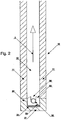
- outer walls of a building according to the invention are formed from outer wall elements 10.
- Each outer wall element 10 consists of two plates 11, which are separated by spacer strips 12 held at a distance and the spacer bar 12th connected to each other.
- the lower of the two superimposed in Fig. 1 outer wall elements 10 stands on a threshold 20, from any Material may consist and example of wood material, plastic, Metal or a mineral material, such as concrete od. Like. can be made.
- the threshold 20 has a substantially U-shaped cross-sectional shape with a lower, horizontally oriented web 21 and two legs 22, which protrude upwards.
- the plates 11 of the lower outer wall element 10 are on the upwardly facing ends of the legs 22 of the threshold 20.
- a heater 30 is provided ( Figure 2).
- This consists of a Heat-emitting rod 31, which in the illustrated starting a from a heating medium flowed through pipe 32 is.
- the rod 31 lies on Holders 33, which in turn via an insulating layer 34 on the after stand up-facing surface of the web 21 of the threshold 20.
- the heating element 31 is simply in upwardly open recesses 36 recorded in the holders 33, for example, inserted.
- the upwardly facing surfaces 35 of the holder 33 can, as in the Fig. 1 and Fig. 2 to 2c shown be chamfered, so that the Holder 33 as a centering when placing the wall elements 10th serve on the thresholds 20.
- FIG. 2 shows the lower part of the arrangement of FIG. 1 in enlarged Scale.
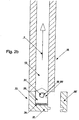
- the two limbs 22 the threshold 20 and accordingly the holder 33 is formed higher as in the embodiment of FIG. 2.
- Fig. 2b an embodiment is shown in which the one leg 22 'of the threshold 20 is removable, so that the tube 32 of the Heating device 31 from the side in the open to the side Recesses 36 'in the holders 33 can also be inserted, if a wall element 10 is already placed on the threshold 20 has been.
- This allows, for example, not only retrospectively Insert or replace pipes 32, but also repairs perform.
- Fig. 2c shows a modification of the embodiment of Fig. 2b at the holder 33 as in the embodiment of FIGS. 1 and 2 have upwardly open recesses 36 for inserting the tubes 32, although here, too, the leg 22 'of the threshold 20 removable is trained.
- the tubes 32 of the heater 31 may be finned tubes 32 and / or tubes with external projections in the form of rods, discs or plates to increase the heat-emitting area of the tubes 32.
- the holders 33 are made of metal, they also act as Magnifications of the heat-emitting surface of the tubes 32 of the Heating device 31.
- Fig. 3 the arrangement of the two is arranged one above the other Wall elements 10 and the threshold 20 shown in an oblique view, wherein It is also shown that the holder 33 over the length of the threshold 20th distributed, and for example in groups of several (two) holders 33 are summarized.
- the heating rod 31 is in the cavity 13 between the plates 11 of the wall elements 10 given off heat.
- the amount of the given heat preferably chosen so that heat losses, the would occur when heat from the interior of a wall elements 10th Composed building steps outward, just balanced become. So it becomes the K value of one of the wall elements 10 formed wall reduced to zero.
- a cooling device is provided.
- Such a cooling device is preferably in the region of the upper end of a wall elements 10th assembled wall of a building arranged.
- the holder 33 may be made of any material, preferably it is when the holder 33 made of plastic or the like or from Wood material are formed.
- the heating element 31 is also an electrical resistance heating element or wire be.
- measures can also be taken around the heated through the cavity of the outer wall elements 10, heated Air in roof elements 50 to flow, even there Heat losses compensate, so the K value in the roof area too reduce or preferably lower to zero.
- measures can also be taken around the heated through the cavity of the outer wall elements 10, heated Air in roof elements 50 to flow, even there Heat losses compensate, so the K value in the roof area too reduce or preferably lower to zero.
- the lower plates 51st the roof elements 50 recesses 52 provided so that the cavity between the plates of the roof elements 50 with the cavity 13 between the wall elements 10 communicates.
- the cavity between the Plates of the roof elements 50 is in the region of the outer plate 11 of Wall elements 10 opened by a plate 53.
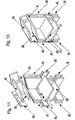
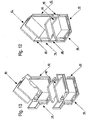
- FIGS. 10 to 13 show a schematic representation of a Corner of a building according to the invention with outer wall elements 10, a ceiling element 40 and a roof element 50.
- FIGS. 10 to 13 show that the cavities in the outer wall elements 10 with the Cavities in the roof elements 50 kommmuniplastic, as appropriate Recesses 41 and 52 in the edge region of ceiling element 40 and roof element 50 are provided.
- the heater 30 is on a longitudinal beam 60 via mounting bracket 61 mounted.
- the Headband 61 are anchored with their legs in the carrier 60.
- the carrier 60 is in turn carried by a profiled strip 62, the one web 63 and two of these upwardly projecting leg 64 owns.
- the legs 64 are located above projections 65 (longitudinal Ribs or nubs) on the side surfaces of the longitudinal beam 60 on.
- the profile strip 62 is above an insulating layer 60 on a under their component to be arranged on.
- the threshold indicated in FIG. 14 is below a wall element 10 arranged so that the heating device 30, in particular the pipe 32nd the same, in the cavity 13 between the plates 11 of a wall element 10 comes to rest.
- a building consists of clamshell-shaped wall elements 10 and ceiling elements 40 and roof elements 50, which also clamshell are formed.
- the wall elements 10 stand with their lower ends on sleepers 20, in which a heater 30th is provided.
- the heater 30 gives so much heat to the Cavity 13 between the plates 11 of the wall elements 10 and the Ceiling elements 40, as well as the roof elements 50 from that heat, the lost by heat transfer through the outer shell of the building, is at least partially, in particular, completely compensated. The result is thus the heat transfer through the outer walls and / or the roof elements 50 of the building to zero or almost on Zero reduced.
Landscapes
- Engineering & Computer Science (AREA)
- Architecture (AREA)
- Structural Engineering (AREA)
- Civil Engineering (AREA)
- Physics & Mathematics (AREA)
- Mechanical Engineering (AREA)
- Electromagnetism (AREA)
- General Engineering & Computer Science (AREA)
- Combustion & Propulsion (AREA)
- Chemical & Material Sciences (AREA)
- Thermal Sciences (AREA)
- Life Sciences & Earth Sciences (AREA)
- Sustainable Development (AREA)
- Building Environments (AREA)
- Finishing Walls (AREA)
- Panels For Use In Building Construction (AREA)
Claims (21)
- Bâtiment constitué d'éléments de mur extérieur (10), d'éléments de toit (50) et le cas échéant d'éléments de plafond (40), dans lequel au moins les éléments de mur extérieur (10) sont conçus à double paroi et comportent des plaques (11) qui sont assemblées entre elles à une certaine distance l'une de l'autre grâce à des éléments d'écartement (12) en formant au moins un espace creux (13) dans l'élément de mur extérieur (10) et dans lequel il est prévu dans la partie inférieure d'éléments de mur extérieur (10) dans l'espace creux (13) entre les plaques (11) des éléments de paroi extérieur (10) un dispositif (30) pour l'amenée de chaleur dans l'espace creux des éléments de paroi extérieur (10), caractérisé en ce que le dispositif (30) est prévu pour amener de la chaleur exclusivement dans un embasement (20) sur lequel les éléments de paroi extérieur (10) sont dressés.
- Bâtiment selon la revendication 1, caractérisé en ce que l'embasement (20) a une section transversale en forme de U et en ce que les plaques (11) des éléments de paroi extérieur (10) sont dressées sur les branches (22), dirigées vers le haut, de l'embasement (20).
- Bâtiment selon la revendication 1 ou 2, caractérisé en ce que le dispositif de chauffage (30) a une source de chaleur (31) en forme de barre.
- Bâtiment selon la revendication 3, caractérisé en ce que la source de chaleur (31) en forme de barre est une barre chauffante à résistance électrique ou un fil chauffant électrique.
- Bâtiment selon la revendication 3, caractérisé en ce que la source de chaleur (31) en forme de barre est un tuyau (32) traversé par un fluide calorifique.
- Bâtiment selon la revendication 3 ou 4, caractérisé en ce que la source de chaleur (31) en forme de barre est logée dans des appuis (33) qui sont globalement en forme de U et qui sont placés dans l'espace creux, ouvert vers le haut, de l'embasement (20).
- Bâtiment selon la revendication 6, caractérisé en ce qu'une couche isolante (34) est prévue entre les appuis (33) et la traverse (21) de l'embasement (20).
- Bâtiment selon la revendication 6 ou 7, caractérisé en ce que les surfaces terminales (35) des appuis (33), lesquelles surfaces terminales sont prévues à côté de l'espace de logement (36) ouvert vers le haut pour la source de chaleur (31) en forme de barre, sont inclinées vers les branches (22) de l'embasement (20).
- Bâtiment selon l'une des revendications 1 à 8, caractérisé en ce que des ouvertures (41) sont prévues dans la zone d'éléments de plafond (40) faisant suite aux éléments de mur extérieur (10).
- Bâtiment selon la revendication 9, caractérisé en ce que les ouvertures (41) sont prévues dans des plaques de l'élément de plafond (40).
- Bâtiment selon la revendication 9 ou 10, caractérisé en ce que les extrémités latérales des éléments de plafond (40) sont fermées par des plaques (42).
- Bâtiment selon l'une des revendications 1 à 11, caractérisé en ce que des évidements (52) sont prévus dans des plaques inférieures, en position d'usage, d'éléments de toit (50).
- Bâtiment selon la revendication 12, caractérisé en ce que les extrémités latérales des éléments de toit (50) sont fermées par des plaques (53).
- Bâtiment selon la revendication 11 ou 13, caractérisé en ce que les plaques de fermeture (42) resp. (53) sont alignées avec les plaques extérieures (11) des éléments de mur (10).
- Bâtiment selon l'une des revendications 1 à 14, caractérisé en ce que les tuyaux (32) du dispositif de chauffage (30) sont fixés dans la zone de l'embasement (20) par des appuis (61) avec un support (60) longitudinal disposé dans la zone inférieure de l'espace creux (13) d'éléments de mur (10).
- Bâtiment selon la revendication 15, caractérisé en ce que le support (60) est maintenu dans une baguette profilée (62).
- Bâtiment selon la revendication 16, caractérisé en ce que la baguette profilée (62) a une traverse horizontale (63) sur laquelle les extrémités inférieures des plaques (11) de l'élément de mur (10) sont dressées.
- Bâtiment selon la revendication 16 ou 17, caractérisé en ce que la baguette profilée (62) comporte des branches (64) qui s'éloignent de la traverse horizontale (63) et entre lesquelles le support longitudinal (60) est disposé.
- Bâtiment selon la revendication 18, caractérisé en ce que les branches (64) s'appuient via des parties en saillie (65) contre les surfaces latérales du support longitudinal (60).
- Bâtiment selon la revendication 19, caractérisé en ce que les parties en saillie (65) sont des nervures longitudinales.
- Bâtiment selon la revendication 20, caractérisé en ce que les parties en saillie (65) sont des parties en saillie analogue à des boutons.
Priority Applications (1)
| Application Number | Priority Date | Filing Date | Title |
|---|---|---|---|
| AT03769019T ATE305999T1 (de) | 2002-11-11 | 2003-10-16 | Gebäude mit beheizten hohlwandelementen |
Applications Claiming Priority (3)
| Application Number | Priority Date | Filing Date | Title |
|---|---|---|---|
| AT0169502A ATA16952002A (de) | 2002-11-11 | 2002-11-11 | Gebäude |
| AT16952002 | 2002-11-11 | ||
| PCT/AT2003/000314 WO2004044341A1 (fr) | 2002-11-11 | 2003-10-16 | Batiment a elements de mur creux chauffes |
Publications (2)
| Publication Number | Publication Date |
|---|---|
| EP1497506A1 EP1497506A1 (fr) | 2005-01-19 |
| EP1497506B1 true EP1497506B1 (fr) | 2005-10-05 |
Family
ID=32303955
Family Applications (1)
| Application Number | Title | Priority Date | Filing Date |
|---|---|---|---|
| EP03769019A Expired - Lifetime EP1497506B1 (fr) | 2002-11-11 | 2003-10-16 | Batiment a elements de mur creux chauffes |
Country Status (8)
| Country | Link |
|---|---|
| US (1) | US20060242920A1 (fr) |
| EP (1) | EP1497506B1 (fr) |
| JP (1) | JP2006507432A (fr) |
| AT (1) | ATA16952002A (fr) |
| AU (1) | AU2003277934A1 (fr) |
| DE (1) | DE50301309D1 (fr) |
| ES (1) | ES2248773T3 (fr) |
| WO (1) | WO2004044341A1 (fr) |
Cited By (1)
| Publication number | Priority date | Publication date | Assignee | Title |
|---|---|---|---|---|
| EP2849101A1 (fr) | 2013-09-12 | 2015-03-18 | Ari Griffner Patentholding KG | Procédé destiné à planifier et à ériger des bâtiments |
Families Citing this family (10)
| Publication number | Priority date | Publication date | Assignee | Title |
|---|---|---|---|---|
| SE527761C2 (sv) * | 2004-10-13 | 2006-05-30 | Strategiverket Af Klintberg | Fuktskydd och sätt att fuktskydda ett utrymme |
| US20160194864A1 (en) * | 2015-01-07 | 2016-07-07 | James Walker | Frameless construction using single and double panels |
| US10822790B2 (en) * | 2010-08-24 | 2020-11-03 | Innovative Structural Building Products, Llc | Frameless construction using single and double plenum panels |
| US9604428B2 (en) | 2010-08-24 | 2017-03-28 | James Walker | Ventilated structural panels and method of construction with ventilated structural panels |
| US8534018B2 (en) * | 2010-08-24 | 2013-09-17 | James Walker | Ventilated structural panels and method of construction with ventilated structural panels |
| US9091049B2 (en) | 2010-08-24 | 2015-07-28 | James Walker | Ventilated structural panels and method of construction with ventilated structural panels |
| US9050766B2 (en) | 2013-03-01 | 2015-06-09 | James Walker | Variations and methods of producing ventilated structural panels |
| US8490355B2 (en) * | 2010-08-24 | 2013-07-23 | James Walker | Ventilated structural panels and method of construction with ventilated structural panels |
| KR101244678B1 (ko) | 2011-07-08 | 2013-03-21 | 전용철 | 에어블록 |
| CN114541599B (zh) * | 2022-02-21 | 2023-06-27 | 山东联海建筑科技股份有限公司 | 一种装配式建筑外挂墙板排水结构 |
Family Cites Families (29)
| Publication number | Priority date | Publication date | Assignee | Title |
|---|---|---|---|---|
| US1771268A (en) * | 1927-01-28 | 1930-07-22 | Musgrave Joseph Leslie | Heating and cooling of buildings |
| US2641449A (en) * | 1947-11-14 | 1953-06-09 | John C Antony | Building construction |
| US2843364A (en) * | 1952-04-10 | 1958-07-15 | Kahr Gustaf | Room heating systems |
| DE2244073A1 (de) * | 1972-09-08 | 1974-03-14 | Rigips Baustoffwerke Gmbh | Anschlussprofil |
| US4145852A (en) * | 1976-08-30 | 1979-03-27 | Gerhard Hahn | Construction element |
| SE405029B (sv) * | 1977-04-19 | 1978-11-13 | Samuelsson Sture Lennart | Modulblock och modulsystem for husbyggnad samt sett att tillverka modulblock |
| NL8120009A (nl) * | 1980-01-22 | 1981-12-01 | Platen Magnus H B Von | Werkwijze en middelen voor het verminderen van het warmteverbruik in een gebouw of dergelijke. |
| US4338994A (en) * | 1980-01-28 | 1982-07-13 | Bernd Hewing | Modular panel heater having improved holder devices |
| DE3217617C2 (de) * | 1981-05-16 | 1985-09-12 | Fritz 5880 Lüdenscheid Bindenberger | Halter für Leichtbauplatten |
| DE3505841A1 (de) * | 1985-02-20 | 1986-08-21 | Lorenz 4600 Dortmund Kesting | Vorrichtung zum vermauern grossformatiger mauerkunststeine |
| DE3507951A1 (de) * | 1985-03-06 | 1986-09-11 | Ingenieurbüro Timmer GmbH, 5657 Haan | System zum temperieren von raeumen eines gebaeudes |
| US5269108A (en) * | 1988-10-27 | 1993-12-14 | Saint-Gobain Vitrage International | Heated glazed wall |
| SE8902324L (sv) * | 1989-06-27 | 1990-12-28 | Bengt Valdemar Eggemar | Foerfarande och anordning vid vaermevaexling |
| US5156208A (en) * | 1991-03-07 | 1992-10-20 | Asahi Kogyosha Co., Ltd. | Heat pipe unit and partition panel |
| GB9220888D0 (en) * | 1992-10-05 | 1992-11-18 | Ingram Rex A | Improvements to heating/cooling systems |
| RU2109886C1 (ru) * | 1993-06-24 | 1998-04-27 | Сканска Текник АБ | Теплоизолирующая внешняя стена здания |
| CH692094A5 (de) * | 1995-09-23 | 2002-01-31 | Barcol Air | Kontaktelement und Deckenelement für eine Heiz- und Kühldecke. |
| US5842276A (en) * | 1995-11-13 | 1998-12-01 | Qb Technologies, L.C. | Synthetic panel and method |
| DE19735298A1 (de) * | 1997-08-14 | 1999-01-21 | Nikolai Blumenfeld | System der Wandkanalheizung |
| US6330980B1 (en) * | 1997-11-03 | 2001-12-18 | Joachim Fiedrich | Dry installation of a radiant floor or wall hydronic heating system, metal radiating plates that attach to the edges of side-by-side boards and provide metal slots for holding hot water tubing |
| US5988264A (en) * | 1998-02-11 | 1999-11-23 | Goldsmith; Aaron | Dynamic insulation and air conditioning and radiant heating system |
| US20020069600A1 (en) * | 1998-10-09 | 2002-06-13 | American Structural Composites, Inc. | Composite structural building panels and systems and method for erecting a structure using such panels |
| DE19848003A1 (de) * | 1998-10-17 | 2000-05-04 | D.D.C. Planungs-, Entwicklungs- Und Management Ag | Betondecken- und Wandelement |
| DE19900518A1 (de) * | 1999-01-08 | 2000-07-13 | Erich Wintermantel | Profilelemente, Profilmodule und Kombinationen von Profilelementen und -modulen mit pastösen, verfestigungsfähigen Beschichtungsmassen zum gerichteten Führen von strömungsfähigen Medien sowie deren Anwendung |
| US6283382B1 (en) * | 2000-08-15 | 2001-09-04 | Michael Fitzemeyer | Radiant heating system pipe mounting plate |
| AT413713B (de) * | 2000-09-14 | 2006-05-15 | Jandl Adolf | Gebäude |
| US6754997B2 (en) * | 2001-11-08 | 2004-06-29 | Pete J. Bonin | Utility distribution structure |
| DE10159065A1 (de) * | 2001-12-01 | 2003-06-26 | Pierburg Gmbh | Halterung für elektro-pneumatische Bauteile |
| AU2003226241A1 (en) * | 2002-06-06 | 2003-12-22 | Jack A. Holwerda | Modular wall panel with heated ventilator |
-
2002
- 2002-11-11 AT AT0169502A patent/ATA16952002A/de not_active Application Discontinuation
-
2003
- 2003-10-16 ES ES03769019T patent/ES2248773T3/es not_active Expired - Lifetime
- 2003-10-16 US US10/534,467 patent/US20060242920A1/en not_active Abandoned
- 2003-10-16 WO PCT/AT2003/000314 patent/WO2004044341A1/fr active Application Filing
- 2003-10-16 JP JP2004550541A patent/JP2006507432A/ja not_active Withdrawn
- 2003-10-16 DE DE50301309T patent/DE50301309D1/de not_active Expired - Lifetime
- 2003-10-16 AU AU2003277934A patent/AU2003277934A1/en not_active Abandoned
- 2003-10-16 EP EP03769019A patent/EP1497506B1/fr not_active Expired - Lifetime
Cited By (1)
| Publication number | Priority date | Publication date | Assignee | Title |
|---|---|---|---|---|
| EP2849101A1 (fr) | 2013-09-12 | 2015-03-18 | Ari Griffner Patentholding KG | Procédé destiné à planifier et à ériger des bâtiments |
Also Published As
| Publication number | Publication date |
|---|---|
| ES2248773T3 (es) | 2006-03-16 |
| DE50301309D1 (de) | 2006-02-16 |
| EP1497506A1 (fr) | 2005-01-19 |
| JP2006507432A (ja) | 2006-03-02 |
| AU2003277934A1 (en) | 2004-06-03 |
| ATA16952002A (de) | 2004-06-15 |
| US20060242920A1 (en) | 2006-11-02 |
| WO2004044341A1 (fr) | 2004-05-27 |
Similar Documents
| Publication | Publication Date | Title |
|---|---|---|
| AT413713B (de) | Gebäude | |
| EP1497506B1 (fr) | Batiment a elements de mur creux chauffes | |
| EP2432673B1 (fr) | Dispositif de chauffage pour véhicules ferroviaires | |
| EP1381740B1 (fr) | Element de bois stratifie prefabrique | |
| EP2653625B1 (fr) | Composant à isolation thermique | |
| EP1734200A1 (fr) | Elément de paroi pour un bâtiment et un elément composite de bois | |
| EP1717386B1 (fr) | Elément de plancher | |
| DE2452373C3 (de) | Wärmedämmendes Wandelement | |
| DE2621938C2 (de) | Fußboden- oder Deckenplatte mit angrenzender Wand | |
| DE102012011903C5 (de) | Elektrische Heizvorrichtung | |
| DE19646812C2 (de) | Heizplatte | |
| DE202019100408U1 (de) | Hybrid-Rollladenkasten mit einer Ziegel-Außenschale und einem Dämm-Einsatz | |
| AT354688B (de) | Dreischichtiges bauelement fuer zerlegbare trennwaende od.dgl. | |
| DE3218910C2 (fr) | ||
| DE3433666A1 (de) | Wandbauelement | |
| AT13709U1 (de) | Holzbaustein als Vollholzhausbausystem | |
| DE3634413C1 (en) | Floor, ceiling or wall heating system | |
| DE3146650A1 (de) | "mauerstein, insbesondere mehrwandstein" | |
| EP1174552A2 (fr) | Elément composite de mur extérieur pour bâtiments d'habitation | |
| EP1782786A2 (fr) | Cabine, en particulier pour sauna | |
| DE10002373A1 (de) | Bauplatte mit integrierter Lastverteilschicht für eine Flächenklimatisieranlage | |
| DE3347973C2 (en) | Air floor-heating system | |
| DE102015107703A1 (de) | Holztafelwand in Holzständerbauweise und Träger für eine solche Holztafelwand | |
| DE102005050293A1 (de) | Mattenförmiger Wärmetauscher | |
| AT274311B (de) | Bauelement |
Legal Events
| Date | Code | Title | Description |
|---|---|---|---|
| PUAI | Public reference made under article 153(3) epc to a published international application that has entered the european phase |
Free format text: ORIGINAL CODE: 0009012 |
|
| 17P | Request for examination filed |
Effective date: 20040923 |
|
| AK | Designated contracting states |
Kind code of ref document: A1 Designated state(s): AT BE BG CH CY CZ DE DK EE ES FI FR GB GR HU IE IT LI LU MC NL PT RO SE SI SK TR |
|
| AX | Request for extension of the european patent |
Extension state: AL LT LV MK |
|
| GRAP | Despatch of communication of intention to grant a patent |
Free format text: ORIGINAL CODE: EPIDOSNIGR1 |
|
| GRAS | Grant fee paid |
Free format text: ORIGINAL CODE: EPIDOSNIGR3 |
|
| GRAA | (expected) grant |
Free format text: ORIGINAL CODE: 0009210 |
|
| AK | Designated contracting states |
Kind code of ref document: B1 Designated state(s): AT BE BG CH CY CZ DE DK EE ES FI FR GB GR HU IE IT LI LU MC NL PT RO SE SI SK TR |
|
| AX | Request for extension of the european patent |
Extension state: AL LT LV MK |
|
| PG25 | Lapsed in a contracting state [announced via postgrant information from national office to epo] |
Ref country code: CZ Free format text: LAPSE BECAUSE OF FAILURE TO SUBMIT A TRANSLATION OF THE DESCRIPTION OR TO PAY THE FEE WITHIN THE PRESCRIBED TIME-LIMIT Effective date: 20051005 Ref country code: TR Free format text: LAPSE BECAUSE OF FAILURE TO SUBMIT A TRANSLATION OF THE DESCRIPTION OR TO PAY THE FEE WITHIN THE PRESCRIBED TIME-LIMIT Effective date: 20051005 Ref country code: SI Free format text: LAPSE BECAUSE OF FAILURE TO SUBMIT A TRANSLATION OF THE DESCRIPTION OR TO PAY THE FEE WITHIN THE PRESCRIBED TIME-LIMIT Effective date: 20051005 Ref country code: NL Free format text: LAPSE BECAUSE OF FAILURE TO SUBMIT A TRANSLATION OF THE DESCRIPTION OR TO PAY THE FEE WITHIN THE PRESCRIBED TIME-LIMIT Effective date: 20051005 Ref country code: IE Free format text: LAPSE BECAUSE OF FAILURE TO SUBMIT A TRANSLATION OF THE DESCRIPTION OR TO PAY THE FEE WITHIN THE PRESCRIBED TIME-LIMIT Effective date: 20051005 Ref country code: SK Free format text: LAPSE BECAUSE OF FAILURE TO SUBMIT A TRANSLATION OF THE DESCRIPTION OR TO PAY THE FEE WITHIN THE PRESCRIBED TIME-LIMIT Effective date: 20051005 Ref country code: RO Free format text: LAPSE BECAUSE OF FAILURE TO SUBMIT A TRANSLATION OF THE DESCRIPTION OR TO PAY THE FEE WITHIN THE PRESCRIBED TIME-LIMIT Effective date: 20051005 Ref country code: FI Free format text: LAPSE BECAUSE OF FAILURE TO SUBMIT A TRANSLATION OF THE DESCRIPTION OR TO PAY THE FEE WITHIN THE PRESCRIBED TIME-LIMIT Effective date: 20051005 Ref country code: EE Free format text: LAPSE BECAUSE OF FAILURE TO SUBMIT A TRANSLATION OF THE DESCRIPTION OR TO PAY THE FEE WITHIN THE PRESCRIBED TIME-LIMIT Effective date: 20051005 |
|
| REG | Reference to a national code |
Ref country code: GB Ref legal event code: FG4D Free format text: NOT ENGLISH |
|
| REG | Reference to a national code |
Ref country code: CH Ref legal event code: NV Representative=s name: TROESCH SCHEIDEGGER WERNER AG Ref country code: CH Ref legal event code: EP |
|
| PG25 | Lapsed in a contracting state [announced via postgrant information from national office to epo] |
Ref country code: CY Free format text: LAPSE BECAUSE OF FAILURE TO SUBMIT A TRANSLATION OF THE DESCRIPTION OR TO PAY THE FEE WITHIN THE PRESCRIBED TIME-LIMIT Effective date: 20051016 |
|
| GBT | Gb: translation of ep patent filed (gb section 77(6)(a)/1977) |
Effective date: 20051005 |
|
| PG25 | Lapsed in a contracting state [announced via postgrant information from national office to epo] |
Ref country code: BE Free format text: LAPSE BECAUSE OF NON-PAYMENT OF DUE FEES Effective date: 20051031 Ref country code: MC Free format text: LAPSE BECAUSE OF NON-PAYMENT OF DUE FEES Effective date: 20051031 |
|
| REG | Reference to a national code |
Ref country code: IE Ref legal event code: FG4D Free format text: LANGUAGE OF EP DOCUMENT: GERMAN |
|
| PG25 | Lapsed in a contracting state [announced via postgrant information from national office to epo] |
Ref country code: LU Free format text: LAPSE BECAUSE OF NON-PAYMENT OF DUE FEES Effective date: 20051205 |
|
| PG25 | Lapsed in a contracting state [announced via postgrant information from national office to epo] |
Ref country code: BG Free format text: LAPSE BECAUSE OF FAILURE TO SUBMIT A TRANSLATION OF THE DESCRIPTION OR TO PAY THE FEE WITHIN THE PRESCRIBED TIME-LIMIT Effective date: 20060105 Ref country code: SE Free format text: LAPSE BECAUSE OF FAILURE TO SUBMIT A TRANSLATION OF THE DESCRIPTION OR TO PAY THE FEE WITHIN THE PRESCRIBED TIME-LIMIT Effective date: 20060105 Ref country code: DK Free format text: LAPSE BECAUSE OF FAILURE TO SUBMIT A TRANSLATION OF THE DESCRIPTION OR TO PAY THE FEE WITHIN THE PRESCRIBED TIME-LIMIT Effective date: 20060105 Ref country code: GR Free format text: LAPSE BECAUSE OF FAILURE TO SUBMIT A TRANSLATION OF THE DESCRIPTION OR TO PAY THE FEE WITHIN THE PRESCRIBED TIME-LIMIT Effective date: 20060105 |
|
| REF | Corresponds to: |
Ref document number: 50301309 Country of ref document: DE Date of ref document: 20060216 Kind code of ref document: P |
|
| NLV1 | Nl: lapsed or annulled due to failure to fulfill the requirements of art. 29p and 29m of the patents act | ||
| PG25 | Lapsed in a contracting state [announced via postgrant information from national office to epo] |
Ref country code: PT Free format text: LAPSE BECAUSE OF FAILURE TO SUBMIT A TRANSLATION OF THE DESCRIPTION OR TO PAY THE FEE WITHIN THE PRESCRIBED TIME-LIMIT Effective date: 20060306 |
|
| REG | Reference to a national code |
Ref country code: ES Ref legal event code: FG2A Ref document number: 2248773 Country of ref document: ES Kind code of ref document: T3 |
|
| LTIE | Lt: invalidation of european patent or patent extension |
Effective date: 20051005 |
|
| PG25 | Lapsed in a contracting state [announced via postgrant information from national office to epo] |
Ref country code: HU Free format text: LAPSE BECAUSE OF FAILURE TO SUBMIT A TRANSLATION OF THE DESCRIPTION OR TO PAY THE FEE WITHIN THE PRESCRIBED TIME-LIMIT Effective date: 20060406 |
|
| ET | Fr: translation filed | ||
| REG | Reference to a national code |
Ref country code: IE Ref legal event code: FD4D |
|
| PLBE | No opposition filed within time limit |
Free format text: ORIGINAL CODE: 0009261 |
|
| STAA | Information on the status of an ep patent application or granted ep patent |
Free format text: STATUS: NO OPPOSITION FILED WITHIN TIME LIMIT |
|
| 26N | No opposition filed |
Effective date: 20060706 |
|
| BERE | Be: lapsed |
Owner name: GRIFFNER, ARI Effective date: 20051031 |
|
| PGFP | Annual fee paid to national office [announced via postgrant information from national office to epo] |
Ref country code: CH Payment date: 20121024 Year of fee payment: 10 |
|
| PGFP | Annual fee paid to national office [announced via postgrant information from national office to epo] |
Ref country code: GB Payment date: 20121010 Year of fee payment: 10 Ref country code: ES Payment date: 20121001 Year of fee payment: 10 |
|
| PGFP | Annual fee paid to national office [announced via postgrant information from national office to epo] |
Ref country code: FR Payment date: 20131023 Year of fee payment: 11 |
|
| PGFP | Annual fee paid to national office [announced via postgrant information from national office to epo] |
Ref country code: IT Payment date: 20131016 Year of fee payment: 11 |
|
| REG | Reference to a national code |
Ref country code: CH Ref legal event code: PL |
|
| GBPC | Gb: european patent ceased through non-payment of renewal fee |
Effective date: 20131016 |
|
| PG25 | Lapsed in a contracting state [announced via postgrant information from national office to epo] |
Ref country code: CH Free format text: LAPSE BECAUSE OF NON-PAYMENT OF DUE FEES Effective date: 20131031 Ref country code: LI Free format text: LAPSE BECAUSE OF NON-PAYMENT OF DUE FEES Effective date: 20131031 Ref country code: GB Free format text: LAPSE BECAUSE OF NON-PAYMENT OF DUE FEES Effective date: 20131016 |
|
| REG | Reference to a national code |
Ref country code: ES Ref legal event code: FD2A Effective date: 20150709 |
|
| PG25 | Lapsed in a contracting state [announced via postgrant information from national office to epo] |
Ref country code: ES Free format text: LAPSE BECAUSE OF NON-PAYMENT OF DUE FEES Effective date: 20131017 |
|
| REG | Reference to a national code |
Ref country code: FR Ref legal event code: ST Effective date: 20150630 |
|
| PG25 | Lapsed in a contracting state [announced via postgrant information from national office to epo] |
Ref country code: FR Free format text: LAPSE BECAUSE OF NON-PAYMENT OF DUE FEES Effective date: 20141031 Ref country code: IT Free format text: LAPSE BECAUSE OF NON-PAYMENT OF DUE FEES Effective date: 20141016 |
|
| PGFP | Annual fee paid to national office [announced via postgrant information from national office to epo] |
Ref country code: DE Payment date: 20161102 Year of fee payment: 14 |
|
| PGFP | Annual fee paid to national office [announced via postgrant information from national office to epo] |
Ref country code: AT Payment date: 20161025 Year of fee payment: 14 |
|
| REG | Reference to a national code |
Ref country code: DE Ref legal event code: R119 Ref document number: 50301309 Country of ref document: DE |
|
| REG | Reference to a national code |
Ref country code: AT Ref legal event code: MM01 Ref document number: 305999 Country of ref document: AT Kind code of ref document: T Effective date: 20171016 |
|
| PG25 | Lapsed in a contracting state [announced via postgrant information from national office to epo] |
Ref country code: DE Free format text: LAPSE BECAUSE OF NON-PAYMENT OF DUE FEES Effective date: 20180501 |
|
| PG25 | Lapsed in a contracting state [announced via postgrant information from national office to epo] |
Ref country code: AT Free format text: LAPSE BECAUSE OF NON-PAYMENT OF DUE FEES Effective date: 20171016 |