EP1497174B1 - Train d'atterrissage pour aeronef - Google Patents
Train d'atterrissage pour aeronef Download PDFInfo
- Publication number
- EP1497174B1 EP1497174B1 EP03746852A EP03746852A EP1497174B1 EP 1497174 B1 EP1497174 B1 EP 1497174B1 EP 03746852 A EP03746852 A EP 03746852A EP 03746852 A EP03746852 A EP 03746852A EP 1497174 B1 EP1497174 B1 EP 1497174B1
- Authority
- EP
- European Patent Office
- Prior art keywords
- door
- doors
- closed
- assembly according
- longitudinal axis
- Prior art date
- Legal status (The legal status is an assumption and is not a legal conclusion. Google has not performed a legal analysis and makes no representation as to the accuracy of the status listed.)
- Expired - Lifetime
Links
Images


Classifications
-
- B—PERFORMING OPERATIONS; TRANSPORTING
- B64—AIRCRAFT; AVIATION; COSMONAUTICS
- B64C—AEROPLANES; HELICOPTERS
- B64C25/00—Alighting gear
- B64C25/02—Undercarriages
- B64C25/08—Undercarriages non-fixed, e.g. jettisonable
- B64C25/10—Undercarriages non-fixed, e.g. jettisonable retractable, foldable, or the like
- B64C25/16—Fairings movable in conjunction with undercarriage elements
Definitions
- the present invention relates to an aircraft landing gear assembly.
- a landing gear of an aircraft is typically movable between a deployed position, where the landing gear extends downwardly from the aircraft and wheels of the landing gear can engage a runway, and a stored position where the landing gear is accommodated within appropriately shaped bays in the aircraft's fuselage or wing. So as not to interfere with the overall aerodynamic properties of the aircraft in flight, the bays are provided with doors which, when closed, conform to the shape of the aircraft body.
- a pair of doors are provided.
- the opening or aperture of the bay accommodating the landing gear is closed across by the doors with adjacent edges of the doors extending along a generally longitudinal axis spanning the aperture.
- Each door is hinged about a generally horizontal and longitudinal axis in the region of the edge of the door opposite to the edge adjoining the other door, allowing the doors to be rotated downwardly about the axes to open positions in which the doors extend approximately vertically downwardly from the aircraft body.
- the size of the pair of doors depends upon the size of the aperture that the doors must close over and the aperture must in turn be sufficiently large to allow passage of the landing gear during deployment. As a result, if the landing gear is relatively large the doors must in turn be relatively large. Especially in the case of large aircraft, it may be desirable to have landing gears deployed in close proximity to one another. In such a case, however, it is important that the doors associated with one landing gear do not interfere with the deployment of an adjacent landing gear. Thus the size of a door, even when fully open, may need to be limited to avoid interference with an adjacent landing gear.
- United States Patent No 2, 406, 701 discloses an aircraft landing gear arrangement including a pair of landing gear bay doors pivoting about generally longitudinal axes and a further door pivoting about a generally transverse axis.
- International Patent Application No WO 01/56878 A1 discloses an aircraft landing gear door assembly in which different doors are actuated by a linked mechanism and are operated by a prime mover separate from the landing gear leg.
- United Kingdom Patent No. 537, 234 discloses an aircraft landing gear assembly in which a door for a landing gear bay pivots about an axis transverse to the longitudinal axis of the aircraft which transverse axis is spaced above the aperture closed by the bay doors.
- EP 1 129 938 A1 discloses an aircraft landing gear door assembly in which a door opens through a space vacated by an adjacent opening door.
- an aircraft landing gear door assembly including a plurality of doors moveable between open positions, in which landing gear can be deployed through an aperture, and closed positions, in which the doors are closed across the aperture, the plurality of doors including a first door mounted for rotational movement between closed and open positions about a first generally longitudinal axis and a transverse door mounted for rotational movement between closed and open positions about a generally horizontal axis that is transverse to the first generally longitudinal axis.
- transverse door allows the length of the first door to be reduced from that which would otherwise be required to allow passage of the landing gear. Such reduction in the length of the first door may avoid the first door interfering with the deployment of a neighbouring landing gear as well as being advantageous from an aerodynamic or noise viewpoint.
- a "generally" longitudinal axis to signify that the axis is in a direction generally aligned with the longitudinal axis of the aircraft fuselage, rather than being transverse thereto. It is not, however, essential for the axis of rotation to be precisely aligned with the longitudinal axis of the aircraft fuselage and indeed in particular cases it may be preferred that the axis of rotation is at an acute angle to the longitudinal axis.
- transverse door merely because the door is one mounted for rotational movement about a generally horizontal axis that is transverse to the first generally longitudinal axis. Whilst in a preferred embodiment of the invention, the longest dimension of the transverse door is in a direction transverse to the first generally longitudinal axis this need not be so; for example, it is possible for the length of the transverse door measured along the longitudinal axis to be greater than its width measured along its transverse axis of rotation.
- the first door is preferably mounted for fixed-axis rotational movement about the first generally longitudinal axis.
- the transverse door is preferably mounted for fixed-axis rotational movement about the transverse generally horizontal axis. Whilst it is possible for a door to be mounted such that its movement is a complex combination of translational and rotational movements, fixed-axis rotation provides a simple and reliable design.
- the assembly preferably further includes a linkage mechanism and a prime mover.
- the linkage mechanism preferably connects the plurality of doors to the prime mover such that the prime mover is effective to operate all the plurality of doors. In that way synchronized movement of the doors can be assured.
- the prime mover preferably comprises a linear actuator, one stroke of the actuator in one direction being effective to move the doors from the closed positions to the open positions and one stroke of the actuator in the opposite direction being effective to move the doors from the open positions to the closed positions.
- the transverse door is disposed at least mostly above the aperture in its open position. It is preferred that all of the transverse door is disposed above the aperture in its open position. By raising the transverse door as it opens, it is possible to keep the transverse door entirely within the landing gear bay and therefore avoid undesirable aerodynamic effects and/or noise.
- the first door preferably projects downwardly from the aperture in its open position.
- the transverse door may be fore or aft of the first door but is aft of the first door in a preferred embodiment of the invention described below.
- the plurality of doors include a second door moveable between closed and open positions, the second door being adjacent to the first door in the closed positions of the doors, the first door being so mounted that its rotational movement from its closed position to its open position involves movement of at least part of the first door through space which is occupied by the second door in its closed position and vacated by the second door in its open position.
- a second door vacated by the second door in its open position By providing a second door which when open allows the first door to move through space which would otherwise have been blocked, it becomes possible to mount the first door in a way that would not otherwise be possible.
- the first door can be arranged such that its outer longitudinal edge moves upwardly and outwardly as the door moves from its closed to its open position.
- the uppermost part of the door may be raised significantly from its position when the door is closed, whereby the door projects less far downwardly in its open position than would be the case if the outer longitudinal edge of the door were hinged about a generally horizontal and longitudinal axis passing through the edge of the door.
- the second door is preferably mounted for fixed-axis rotational movement about a second generally longitudinal axis.
- the first generally longitudinal axis is preferably disposed at a location vertically spaced above the level of the opening and also preferably disposed in a region overlying the locations of adjacent edges of the first and second doors when they are closed.
- the first door By positioning the first generally longitudinal axis at a location vertically spaced above the level of the opening, the first door can readily be arranged to be raised and to enter partway into the bay as the first door is opened. The lateral movement of the first door can be accommodated by the simultaneous opening of the second door.
- the plurality of doors preferably includes a third door mounted for rotational movement between closed and open positions about a third generally longitudinal axis which is preferably a fixed axis, the first and third doors defining a pair of doors on opposite sides of the aperture.
- the plurality of doors preferably further includes a fourth door moveable between closed and open positions, the fourth door being adjacent to the third door in the closed positions of the doors, the third door being so mounted that its rotational movement from its closed position to its open position involves movement of at least part of the third door through space which is occupied by the fourth door in its closed position and vacated by the fourth door in its open position.
- the third door is preferably mounted for fixed-axis rotational movement about a third generally longitudinal axis, which is preferably disposed at a location vertically spaced above the level of the aperture and, preferably, in a region overlying the locations of adjacent edges of the third and fourth doors when they are closed.
- the fourth door is preferably mounted for fixed-axis rotational movement about a fourth generally longitudinal axis. Whilst reference is made to third and fourth doors, it should be understood that it is within the scope of the invention to provide a door assembly including the third door or both the third and fourth doors without these being the door referred to herein as the second door.
- the invention also provides an aircraft including a landing gear assembly as described herein.
- the aircraft may include a further landing gear which when deployed is adjacent to one end of the first door when in its open position, the transverse door being disposed adjacent to said one end of the first door when the doors are in their closed positions.
- the transverse door were instead part of the first door, the first door would interfere with the adjacent landing gear when that gear was deployed and the first door was in its open position. The provision of the separate transverse door avoids such interference.
- the doors of the door assembly of the embodiment described herein are movable between an open position, wherein a single landing gear may pass out of or into the relevant landing gear bay of the aircraft and a closed position, wherein the landing gear is stored in the bay and the doors conform to the shape of the surrounding part of the aircraft.
- the structure and operation of the door assembly will be described by referring firstly to the doors, the axes about which they are arranged to rotate and the positions that they occupy in the open and closed positions. Thereafter the mountings and linkages that achieve the desired movements will be described.
- the door assembly shown includes three doors: a first door 1, a second door 2, and a door 3.
- the first door 1 is mounted for rotation about a first longitudinal axis 11.
- the second door 2 is mounted for rotation about a second longitudinal axis 12, parallel to the axis 11.
- the door 3, referred to herein, as a transverse door, is mounted for rotation about an axis 13 that is substantially horizontal and substantially perpendicular to the longitudinal axes 11 and 12.
- Each door is mounted with only one degree of freedom, namely rotation about a fixed axis.
- Each of the doors is, however, rotatable about an axis spaced from any part of the door and therefore rotation of each door about its respective axis of rotation as it moves between its open and closed positions causes both a change in the orientation of the door and a displacement of the door as will now be further described.
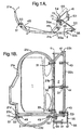
- the configuration of the three doors 1, 2, 3, when closed, is shown schematically in Fig. 1E.
- the first door 1 is bounded by longitudinal side edges 21a and 21b, a curved fore edge 21c and a straight aft edge 21d.
- the second door 2 is of similar length to the first door 1 and is bounded by longitudinal side edges 22a and 22b and fore and aft edges 22c and 22d.
- the side edge 21b of the first door 1 lies immediately adjacent to, and is of similar length to, the side edge 22a of the second door 2 when the doors are closed.
- the transverse door 3 is of much shorter length than the doors 1 and 2 and of very approximately semi-circular shape.
- the transverse door 3 is defined by a straight fore edge 23c, immediately adjacent to and of similar length to the aft edge 21d of the first door, and a curved edge 23d of very approximately semi-circular shape.
- the doors 1 and 3 when closed together define an approximately oval shape with the door 2 providing an extension to that shape on one side. It will be understood that in their closed positions shown in Figs. 1A to 1E, the three doors 1, 2, 3 fill the aperture (or as explained below one half of the aperture) through which landing gear is to be deployed and the shape of that aperture in the described embodiment is therefore the shape defined by the outer edges of the doors 1, 2 and 3 in Figs. 1A to 1E.
- the fixed axis of rotation 11 of the first door 1 is spaced a distance above the door and at a position directly overlying the edge 21b of the first door.
- the door rotates through an angle of about 75 degrees when moving from its closed to its open position. Consequently the edge 21b of the first door 1 moves to the right (as seen in Fig. 1A) as the door begins to open and also moves upwardly especially towards the end of its path of movement.
- the top edge 21b of the door is above its closed position and to the right (as seen in Fig. 1A) of its closed position.
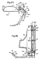
- the fixed axis of rotation 12 of the second door 2 is slightly above and to the right (as seen in Fig. 1A) of the edge 22b of the second door.
- the door rotates through an angle of about 75 degrees when moving from its closed position to its open position.
- the second door 2 therefore moves to the right as it opens with only slight upward movement of the top edge 22b of the door.
- the fixed axis of rotation 13 of the transverse door 3 is above that of the fixed axis 12, as can be seen in Fig. 1A and is slightly to the inside of the straight edge 23c of the door.
- the door rotates through an angle of a little over 80 degrees when moving from its closed position to its open position.
- the the door 3 in Fig. 1C and Fig. 2C the door rotates through an angle of a little over 80 degrees when moving from its closed position to its open position.
- the transverse door 3 therefore moves upwardly and longitudinally away from the first and second doors as it opens and, in its fully open position, all of the transverse door is above the fixed axis of rotation 12 of the second door 2.
- all of the transverse door is housed within the landing gear bay that is closed by the three doors 1, 2, 3 in their closed positions.
- the existence of the transverse door has very little aerodynamic effect on the aircraft.
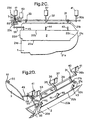
- Figs. 3A and 3B illustrate this benefit schematically: wheels 25 of a neighbouring landing gear are shown.
- a skin structure 26 of an aircraft fuselage extending around the landing gear bay is shown as well as the outline of an internal fixed structure 27 within the fuselage. It can be seen from Fig. 3A that one of the wheels 25 is immediately adjacent to the edge 21d of the first door 1 when that door is in its open position.
- the transverse door 3 were simply a part of the first door 1 that moved with the first door, then the door would interfere with the wheel 25. If the transverse door 3 were simply a fixed part of the aircraft structure then the length of the opening provided by the door assembly would be reduced, which would adversely affect deployment of the landing gear. By providing the transverse door, the opening can be lengthened without causing obstruction by the door assembly, when open, to neighbouring landing gear.
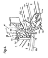
- the door 1 has three arms 31, 32 and 33 fixed to the inside face of the door at equispaced intervals along and adjacent to the side edge 21b of the door 1.
- the central arm 32 is formed of two angled portions 34, 35, the portion 34 being fixed to the door at its remote end and the portion 35 being rotatably landing gear bay. Where the angled portions 34, 35 of each arm meet they are fixedly joined to the middle of a rod 38 which extends parallel to the side edge 21b of the door 1.
- the arms 31 and 33 are each fixed at one end to the door 1 and at the other end to the rod 38.
- the opposite ends of the rod 38 are fixedly joined to ends of respective links 39a and 39b, whose opposite ends are rotatably connected at connections 40 to the distal ends of respective fixed mountings 41 which are fixed to the aircraft structure 27 (see Fig. 3B) inside the landing gear bay.
- the rotatable connections 36 and 40 all lie on the axis of rotation 11 of the door 1 and thus the door 1 is mounted for rotation about the axis 11.
- the door 2 has three arms 43, 44, 45 fixed to the inside of the door at equispaced intervals along and adjacent to the side edge 22b of the door 2.
- Each of the arms 43, 44, 45 is rotatably mounted at a respective connection 46, provided at its end remote from the door 2, to the distal end of a respective fixed mounting (not shown) fixed to the aircraft structure inside the landing gear bay.
- the rotatable connections 46 all lie on the axis of rotation 12 of the door 2 and thus the door 2 is mounted for rotation about the axis 12.
- the door 3 has two arms 48, 49 fixed to the inside of the door adjacent to the straight edge 23c of the door.
- the arm 48 is rotatably connected at a connection 50 provided at its end remote from the door 3 to the distal end of a rod-shaped fixed mounting 51 which is fixed (see Fig. 3B) to the aircraft structure 26 inside the landing gear bay.
- the arm 49 is rotatably connected at a connection 52 provided at its end remote from the door 3 to the distal end of a fixed mounting 53 which is fixed to the aircraft structure 27 (see Fig. 3B) inside the landing gear bay.
- the rotatable connections 50 and 52 both lie on the axis of rotation 13 of the door 3 and thus the door 3 is mounted for rotation about the axis 13.
- a linkage mechanism links the movement of the doors so as to synchronize the movements, as will now be described.
- That linkage comprises a first crank arm 54, a link rod 55 and a second crank arm 56.
- the first crank arm 54 is fixedly joined at one end to the link 39a at its connection 40 on the axis of rotation 11 of the door 1.
- the other end of the first crank arm 54 is rotatably connected to one end of the link rod 55.
- the second crank arm 56 is fixedly joined at one end to the arm 43 at its connection 46 on the axis of rotation 12 of the door 2.
- the other end of the second crank arm 56 is rotatably connected to the other end of the link rod 55.
- rotational movement of the first door 1 causes rotation of the first crank arm 54 which in turn, via the link rod 55, causes rotation of the second crank arm 56 and, with it, the second door 2.
- the amount of angular movement of the door 2 for a given angular movement of the door 1 is determined by the geometry of the linkage and especially the relative lengths of the cranks of the crank arms 54 and 56.
- linkage that synchronizes movement of the door 3 to the movement of the door 1.
- that linkage comprises a crank arm 58, a link rod 63 and a shaft 64.
- the crank arm 58 is fixedly joined via an end portion 59 to the link 39a at its connection 40 on the axis of rotation of the door 1 and, as can be seen in Fig. 4, is an extension of the crank arm 54.
- the crank arm 58 has a portion 60 extending at right angles to the end portion 59, a further cross-part 61, typically an universal joint, and an end portion 62.
- the cross-part 61 allows relative transverse movement of the end portion 62 and the arm 58.
- the end portion 62 is connected to the link rod 63 via a ball joint and the link rod 63 is in turn pivotally connected to one end of the shaft 64.
- the other end of the shaft 64 is fixedly connected to the arm 49 fixed to the transverse door, the shaft passing through a part of the fixed mounting 53 and being rotatably mounted therein to define the rotatable connection 52.
- rotational movement of the first door 1 causes rotation of the crank arm 58 which in turn via the link rod 63 causes rotation of the shaft 64 and, with it, the arm 49 and the transverse door 3.
- the amount of movement of the door 3 for a given movement of the door 1 is determined by the geometry of the linkage.
- the movement of the door 1 is driven by a linear actuator, typically a hydraulic actuator, via a simple linkage.
- a linear actuator typically a hydraulic actuator
- a hydraulic actuator 69 with a piston 70 is pivotally connected at an upper end to the aircraft structure (not shown) and the distal end of the piston 70 is pivotally connected to a rod 71 fixed to the portion 35 of the central arm 32 of the door 1.
- the three doors each rotate about fixed axes under the control of a single prime mover and with their individual movements being synchronized by a linkage connecting the movement of the first door to the movement of the second door and another linkage connecting the movement of the first door to the movement of the third door.
- the arrangement comprises a first door 1, a second door 2, a third door 1a which together with the door 1 provides a pair of doors, a fourth door 2a which opens to allow passage of the door 1a in a manner similar to that in which the door 2 opens to allow passage of the door 1, and finally a transverse door 3a which functions in a manner similar to the transverse door 3 described above.
Claims (18)
- Un assemblage pour train d'atterrissage d'aéronef comprenant une pluralité de trappes (1, 2, 3) pouvant être déplacées entre des positions ouvertes, dans lesquelles un train d'atterrissage peut être déployé par une ouverture, et des positions fermées, dans lesquelles les trappes sont fermées en travers de l'ouverture, la pluralité de trappes comprenant une première trappe (1) montée pour effectuer un déplacement par rotation entre une position fermée et une position ouverte autour d'un premier axe généralement longitudinal (11) dans lequel une première extrémité (21d) de la première trappe se trouve adjacente à un train d'atterrissage supplémentaire (25) lorsque la première trappe est ouverte, et une trappe transversale (3) montée pour effectuer un déplacement par rotation entre des positions fermées et des positions ouvertes autour d'un axe généralement horizontal (13) qui est transversal à l'axe généralement longitudinal (11), la trappe transversale (3) étant positionnée lorsqu'elle est fermée de façon adjacente à la première extrémité (21d) de la première trappe.
- Un assemblage selon la revendication 1, dans lequel la première trappe (1) est montée pour effectuer un déplacement par rotation par rapport à un axe fixe autour du premier axe généralement longitudinal (11).
- Un assemblage selon la revendication 1 ou 2, dans lequel la trappe transversale (3) est montée pour effectuer un déplacement par rotation par rapport à un axe fixe autour de l'axe transversal généralement horizontal (13).
- Un assemblage selon n'importe quelle revendication précédente, comprenant de plus un mécanisme de liaison (54, 55, 56, 58, 63, 64) et un élément de déplacement principal (69), le mécanisme de liaison raccordant la pluralité de trappes (1, 2, 3) à l'élément de déplacement principal de sorte que l'élément de déplacement principal permette de faire fonctionner toute la pluralité de trappes.
- Un assemblage selon la revendication 4, dans lequel l'élément de déplacement principal comporte un actionneur linéaire (69), une course de l'actionneur dans une direction permettant de déplacer les trappes (1, 2, 3) des positions fermées aux positions ouvertes et une course de l'actionneur dans la direction opposée permettant de déplacer les trappes des positions ouvertes aux positions fermées.
- Un assemblage selon n'importe quelle revendication précédente, dans lequel la trappe transversale (3) est disposée au moins en majeure partie au-dessus de l'ouverture dans sa position ouverte.
- Un assemblage selon n'importe quelle revendication précédente, dans lequel la trappe transversale (3) est à l'arrière de la première trappe (1).
- Un assemblage selon n'importe quelle revendication précédente, dans lequel la pluralité de trappes comprend une deuxième trappe (2) pouvant être déplacée entre des positions fermées et des positions ouvertes, la deuxième trappe étant adjacente à la première trappe (1) dans les positions fermées des trappes, la première trappe étant montée de telle sorte que son déplacement par rotation de sa position fermée à sa position ouverte implique le déplacement d'au moins une partie de la première trappe (1) à travers l'espace qui est occupé par la deuxième trappe (2) dans sa position fermée et libéré par la deuxième trappe dans sa position ouverte.
- Un assemblage selon la revendication 8, dans lequel la deuxième trappe (2) est montée pour effectuer un déplacement par rotation par rapport à un axe fixe autour d'un deuxième axe généralement longitudinal (12).
- Un assemblage selon la revendication 8 ou 9, dans lequel le premier axe généralement longitudinal (11) est disposé à un emplacement espacé de façon verticale au-dessus du niveau de l'ouverture.
- Un assemblage selon la revendication 10, dans lequel le premier axe généralement longitudinal (11) est disposé dans une région recouvrant les emplacements de bords adjacents (21b, 22a) de la première trappe et de la deuxième trappe (1, 2) lorsqu'elles sont fermées.
- Un assemblage selon n'importe quelle revendication précédente, dans lequel la pluralité de trappes comprend une troisième trappe (1a) montée pour effectuer un déplacement par rotation entre des positions fermées et des positions ouvertes autour d'un troisième axe généralement longitudinal, la première trappe et la troisième trappe (1, 1a) définissant une paire de trappes sur des côtés opposés de l'ouverture.
- Un assemblage selon la revendication 12, dans lequel la pluralité de trappes comprend une quatrième trappe (2a) pouvant être déplacée entre des positions fermées et ouvertes, la quatrième trappe étant adjacente à la troisième trappe (1a) dans les positions fermées des trappes, la troisième trappe (1a) étant montée de telle sorte que son déplacement par rotation de sa position fermée à sa position ouverte implique le déplacement d'au moins une partie de la troisième trappe (1a) à travers l'espace qui est occupé par la quatrième trappe (2a) dans sa position fermée et libéré par la quatrième trappe (2a) dans sa position ouverte.
- Un assemblage selon la revendication 13, dans lequel la troisième trappe (1a) est montée pour effectuer un déplacement par rotation par rapport à un axe fixe autour d'un troisième axe généralement longitudinal.
- Un assemblage selon la revendication 13 ou 14, dans lequel le troisième axe généralement longitudinal est disposé à un emplacement espacé verticalement au-dessus du niveau de l'ouverture.
- Un assemblage selon la revendication 15, dans lequel le troisième axe généralement longitudinal est disposé dans une région recouvrant les emplacements de bords adjacents de la troisième trappe et de la quatrième trappe (1a, 2a) lorsqu'elles sont fermées.
- Un assemblage selon n'importe lesquelles des revendications 13 à 16, dans lequel la quatrième trappe (2a) est montée pour effectuer un déplacement par rotation par rapport à un axe fixe autour d'un quatrième axe généralement longitudinal.
- Un aéronef comprenant un assemblage pour train d'atterrissage selon n'importe quelle revendication précédente.
Applications Claiming Priority (3)
| Application Number | Priority Date | Filing Date | Title |
|---|---|---|---|
| GBGB0208963.9A GB0208963D0 (en) | 2002-04-19 | 2002-04-19 | Landing gear door assembly |
| GB0208963 | 2002-04-19 | ||
| PCT/GB2003/001387 WO2003089297A1 (fr) | 2002-04-19 | 2003-03-28 | Ensemble trappe de train d'atterrissage |
Publications (2)
| Publication Number | Publication Date |
|---|---|
| EP1497174A1 EP1497174A1 (fr) | 2005-01-19 |
| EP1497174B1 true EP1497174B1 (fr) | 2006-04-19 |
Family
ID=9935130
Family Applications (1)
| Application Number | Title | Priority Date | Filing Date |
|---|---|---|---|
| EP03746852A Expired - Lifetime EP1497174B1 (fr) | 2002-04-19 | 2003-03-28 | Train d'atterrissage pour aeronef |
Country Status (8)
| Country | Link |
|---|---|
| US (1) | US7287726B2 (fr) |
| EP (1) | EP1497174B1 (fr) |
| AT (1) | ATE323643T1 (fr) |
| AU (1) | AU2003226518A1 (fr) |
| DE (1) | DE60304697T2 (fr) |
| ES (1) | ES2258228T3 (fr) |
| GB (1) | GB0208963D0 (fr) |
| WO (1) | WO2003089297A1 (fr) |
Families Citing this family (19)
| Publication number | Priority date | Publication date | Assignee | Title |
|---|---|---|---|---|
| GB0214119D0 (en) * | 2002-06-19 | 2002-07-31 | Airbus Uk Ltd | Landing gear door assembly |
| FR2866313B1 (fr) * | 2004-02-13 | 2007-04-20 | Airbus France | Trappe articulee pour train d'atterrissage d'aeronef |
| FR2869013B1 (fr) * | 2004-04-20 | 2007-07-13 | Airbus France Sas | Deflecteur de flux aerodynamique pour train d'atterrissage d'aeronef |
| ES2272147B1 (es) * | 2004-12-31 | 2008-04-16 | Airbus España, S.L. | Dispositivo para facilitar la bajada de un tren de aterrizaje por gravedad. |
| FR2911321B1 (fr) | 2007-01-11 | 2009-07-10 | Airbus Sa Sa | Systeme d'ouverture et de fermeture d'une case de train d'atterissage d'un aeronef |
| FR2933670B1 (fr) * | 2008-07-08 | 2011-04-08 | Airbus France | Systeme d'ouverture et de fermeture de trappe pour case de train d'atterrissage d'un aeronef |
| BRPI0921264A2 (pt) * | 2008-12-05 | 2018-10-23 | Messier Downty Inc | porta de compartimento de trem de pouso com mecanisco de gancho duplo |
| FR2962410B1 (fr) * | 2010-07-09 | 2013-07-12 | Airbus Operations Sas | Procede de reglage des trappes de case de train d'atterrissage et trappe de mise en oeuvre |
| FR2993242A1 (fr) * | 2012-07-12 | 2014-01-17 | Aerolia | Dispositif d'ouverture de trappe de case de train |
| FR2998868B1 (fr) * | 2012-11-30 | 2016-02-05 | Airbus Operations Sas | Dispositif de fixation intermediaire entre un fuselage d'aeronef et un train d'atterrissage d'aeronef |
| JP6228394B2 (ja) * | 2013-06-27 | 2017-11-08 | 三菱航空機株式会社 | 航空機の主脚室、及び、航空機 |
| JP6254787B2 (ja) * | 2013-08-08 | 2017-12-27 | 三菱航空機株式会社 | 航空機の脚収納部、および航空機 |
| US20150069178A1 (en) * | 2013-09-09 | 2015-03-12 | The Boeing Company | Fuselage-mounted landing gear assembly for use with a low wing aircraft |
| FR3014836B1 (fr) * | 2013-12-16 | 2016-02-05 | Airbus Operations Sas | Dispositif d'ouverture ou de fermeture concomitante de deux volets d'une trappe d'un train d'atterrissage |
| FR3020340B1 (fr) | 2014-04-29 | 2017-12-01 | Airbus Operations Sas | Aeronef comportant deux portes de train d'atterrissage et un systeme de manœuvre destine a manœuvrer lesdites portes |
| GB2528131A (en) * | 2014-07-11 | 2016-01-13 | Airbus Uk Ltd | Door abutment |
| BR102015031730A2 (pt) * | 2015-12-17 | 2017-06-20 | Embraer Sa | Access door for aircraft and aircraft |
| CN113602484B (zh) * | 2021-08-26 | 2022-08-23 | 中国商用飞机有限责任公司 | 起落架收放系统及包括该系统的飞机 |
| US11919624B2 (en) * | 2022-03-15 | 2024-03-05 | Safran Landing Systems Canada Inc. | Landing gear door installation |
Family Cites Families (26)
| Publication number | Priority date | Publication date | Assignee | Title |
|---|---|---|---|---|
| US2180462A (en) * | 1937-12-16 | 1939-11-21 | Seversky Aircraft Corp | Aircraft structure |
| US2457625A (en) * | 1939-01-19 | 1948-12-28 | Amiot Felix | Controlling means, especially for doors |
| GB537234A (en) | 1939-12-11 | 1941-06-13 | Gen Aircraft Ltd | Improvements in closure devices for storage compartments of aircraft |
| US2406710A (en) * | 1943-10-04 | 1946-08-27 | Glenn L Martin Co | Landing gear housing door |
| US2604281A (en) * | 1948-08-11 | 1952-07-22 | Glenn L Martin Co | Actuating mechanism and support for bomb bay doors |
| US2548832A (en) * | 1948-09-17 | 1951-04-10 | Curtiss Wright Corp | Combined landing gear door and fluid foil |
| GB756111A (en) | 1953-08-11 | 1956-08-29 | Morane Saulnier | Improvements in retractable landing gears for aircraft |
| US2921501A (en) * | 1955-06-13 | 1960-01-19 | Sncaso | Aircraft load-release device |
| US2921759A (en) * | 1955-12-09 | 1960-01-19 | North American Aviation Inc | Retractable landing gear |
| US2963246A (en) * | 1956-05-21 | 1960-12-06 | Chance Vought Aircraft Inc | Retractable landing gear for aircraft |
| US2941756A (en) * | 1956-06-21 | 1960-06-21 | Transair Ltd | Retractable landing wheel mechanism for aircraft |
| GB847382A (en) | 1956-06-21 | 1960-09-07 | Transair Ltd | Improvements in douglas d.c. 3 and like aircraft |
| US3156439A (en) * | 1962-08-27 | 1964-11-10 | Alexander C Fleury | Manually operated landing gear for light amphibious airplanes |
| FR1352138A (fr) * | 1962-09-25 | 1964-02-14 | Aviation Louis Breguet Sa | Porte de soute pour fuselage d'aéronefs |
| GB1141141A (en) * | 1965-01-19 | 1969-01-29 | Hawker Siddeley Dynamics Ltd | Improvements in or relating to retractable wheel mountings for aircraft |
| DE2924742C2 (de) * | 1979-06-20 | 1983-12-08 | Dornier Gmbh, 7990 Friedrichshafen | Großflugzeug, insbesondere in Schulterdeckerbauart |
| US4412665A (en) * | 1981-11-02 | 1983-11-01 | Mcdonnell Douglas Corporation | 3-Wheeled levered trailing beam landing gear |
| US4845804A (en) * | 1987-06-04 | 1989-07-11 | Underkart Industries Of Canada Ltd. | Retractable caster |
| US5692703A (en) * | 1996-05-10 | 1997-12-02 | Mcdonnell Douglas Corporation | Multiple application wheel well design |
| FR2782495B1 (fr) * | 1998-08-19 | 2000-11-10 | Aerospatiale | Structure avant d'avion |
| GB9907642D0 (en) * | 1999-04-06 | 1999-05-26 | British Aerospace | An aircraft landing gear |
| GB9921379D0 (en) * | 1999-09-10 | 1999-11-10 | British Aerospace | Aircraft landing gear |
| GB0002264D0 (en) | 2000-02-02 | 2000-03-22 | British Aerospace | Landing gear doors |
| US6352221B1 (en) * | 2000-03-03 | 2002-03-05 | The Boeing Company | Rotary landing gear assembly |
| US6345786B1 (en) * | 2000-03-03 | 2002-02-12 | The Boeing Company | Linked multi-segment landing gear door for aircraft |
| ES2277250T3 (es) * | 2003-04-07 | 2007-07-01 | Airbus Uk Limited | Conjunto de puertas de tren de aterrizaje. |
-
2002
- 2002-04-19 GB GBGB0208963.9A patent/GB0208963D0/en not_active Ceased
-
2003
- 2003-03-28 EP EP03746852A patent/EP1497174B1/fr not_active Expired - Lifetime
- 2003-03-28 ES ES03746852T patent/ES2258228T3/es not_active Expired - Lifetime
- 2003-03-28 US US10/511,848 patent/US7287726B2/en not_active Expired - Lifetime
- 2003-03-28 AT AT03746852T patent/ATE323643T1/de not_active IP Right Cessation
- 2003-03-28 AU AU2003226518A patent/AU2003226518A1/en not_active Abandoned
- 2003-03-28 DE DE60304697T patent/DE60304697T2/de not_active Expired - Lifetime
- 2003-03-28 WO PCT/GB2003/001387 patent/WO2003089297A1/fr not_active Application Discontinuation
Also Published As
| Publication number | Publication date |
|---|---|
| ES2258228T3 (es) | 2006-08-16 |
| DE60304697T2 (de) | 2006-08-31 |
| US20050103937A1 (en) | 2005-05-19 |
| GB0208963D0 (en) | 2002-05-29 |
| ATE323643T1 (de) | 2006-05-15 |
| US7287726B2 (en) | 2007-10-30 |
| WO2003089297A1 (fr) | 2003-10-30 |
| AU2003226518A1 (en) | 2003-11-03 |
| DE60304697D1 (de) | 2006-05-24 |
| EP1497174A1 (fr) | 2005-01-19 |
Similar Documents
| Publication | Publication Date | Title |
|---|---|---|
| EP1497174B1 (fr) | Train d'atterrissage pour aeronef | |
| EP1615819B1 (fr) | Ensemble trappe de train d'atterrissage | |
| US7338012B2 (en) | Landing gear door with controlled kinematic control | |
| US7510151B2 (en) | Wing with extendable aerodynamic pivoted flaps | |
| CN107429532B (zh) | 用于家具翻盖的支撑装置和具有支撑装置的家具 | |
| US8286916B2 (en) | Retractable aerodynamic device permitting the control of the wake trajectory of an aircraft trap | |
| CA2496871C (fr) | Trappe articulee pour train d'atterrissage d'aeronef | |
| US8393570B2 (en) | Landing flap kinematics driven by way of a pinion drive | |
| US20050194496A1 (en) | Landing gear door assembly | |
| JP5995782B2 (ja) | スラット支持組立体 | |
| US7344179B2 (en) | Retractable hardtop for a vehicle | |
| BRPI0610884A2 (pt) | sistema de abertura e de fechamento de alçapão para compartimento de trem de pouso de uma aeronave | |
| ITMI981920A1 (it) | Sistema a sportello per un velivolo per passeggeri | |
| US6736443B2 (en) | Cover arrangement for vehicles with removable vehicle roof | |
| CN113383643A (zh) | 行割台的枢转设备 | |
| EP0898549B1 (fr) | Volet segmente a courbure variable pour aile d'avion | |
| CN111206842A (zh) | 车辆翻板运动机构 | |
| US7290825B2 (en) | Device used to facilitate the insertion of objects under a folded roof in the boot of a motor vehicle | |
| EP2965986A1 (fr) | Butée pour trappe de train d'atterrissage d'aéronef | |
| EP1334856A2 (fr) | Mécanisme d'ouverture d'une porte à aile d'un véhicule | |
| US10399671B2 (en) | Rear door of a landing gear box comprising an air passage orifice and a closure member of the latter | |
| WO2001056878A1 (fr) | Trappe de train d"atterrissage | |
| EP2353931B1 (fr) | Unité de siège dotée d'un ensemble formant table | |
| EP1619119A2 (fr) | Ensemble d'aile pour avions ultralégers et avion ultraléger avec cette aile | |
| RU2447252C2 (ru) | Узел сдвижной двери для автомобиля |
Legal Events
| Date | Code | Title | Description |
|---|---|---|---|
| PUAI | Public reference made under article 153(3) epc to a published international application that has entered the european phase |
Free format text: ORIGINAL CODE: 0009012 |
|
| 17P | Request for examination filed |
Effective date: 20041102 |
|
| AK | Designated contracting states |
Kind code of ref document: A1 Designated state(s): AT BE BG CH CY CZ DE DK EE ES FI FR GB GR HU IE IT LI LU MC NL PT RO SE SI SK TR |
|
| AX | Request for extension of the european patent |
Extension state: AL LT LV MK |
|
| 17Q | First examination report despatched |
Effective date: 20041216 |
|
| GRAP | Despatch of communication of intention to grant a patent |
Free format text: ORIGINAL CODE: EPIDOSNIGR1 |
|
| RTI1 | Title (correction) |
Free format text: LANDING GEAR ASSEMBLY |
|
| GRAS | Grant fee paid |
Free format text: ORIGINAL CODE: EPIDOSNIGR3 |
|
| GRAA | (expected) grant |
Free format text: ORIGINAL CODE: 0009210 |
|
| AK | Designated contracting states |
Kind code of ref document: B1 Designated state(s): AT BE BG CH CY CZ DE DK EE ES FI FR GB GR HU IE IT LI LU MC NL PT RO SE SI SK TR |
|
| PG25 | Lapsed in a contracting state [announced via postgrant information from national office to epo] |
Ref country code: SI Free format text: LAPSE BECAUSE OF FAILURE TO SUBMIT A TRANSLATION OF THE DESCRIPTION OR TO PAY THE FEE WITHIN THE PRESCRIBED TIME-LIMIT Effective date: 20060419 Ref country code: BE Free format text: LAPSE BECAUSE OF FAILURE TO SUBMIT A TRANSLATION OF THE DESCRIPTION OR TO PAY THE FEE WITHIN THE PRESCRIBED TIME-LIMIT Effective date: 20060419 Ref country code: IT Free format text: LAPSE BECAUSE OF FAILURE TO SUBMIT A TRANSLATION OF THE DESCRIPTION OR TO PAY THE FEE WITHIN THE PRESCRIBED TIME-LIMIT;WARNING: LAPSES OF ITALIAN PATENTS WITH EFFECTIVE DATE BEFORE 2007 MAY HAVE OCCURRED AT ANY TIME BEFORE 2007. THE CORRECT EFFECTIVE DATE MAY BE DIFFERENT FROM THE ONE RECORDED. Effective date: 20060419 Ref country code: LI Free format text: LAPSE BECAUSE OF FAILURE TO SUBMIT A TRANSLATION OF THE DESCRIPTION OR TO PAY THE FEE WITHIN THE PRESCRIBED TIME-LIMIT Effective date: 20060419 Ref country code: RO Free format text: LAPSE BECAUSE OF FAILURE TO SUBMIT A TRANSLATION OF THE DESCRIPTION OR TO PAY THE FEE WITHIN THE PRESCRIBED TIME-LIMIT Effective date: 20060419 Ref country code: FI Free format text: LAPSE BECAUSE OF FAILURE TO SUBMIT A TRANSLATION OF THE DESCRIPTION OR TO PAY THE FEE WITHIN THE PRESCRIBED TIME-LIMIT Effective date: 20060419 Ref country code: CH Free format text: LAPSE BECAUSE OF FAILURE TO SUBMIT A TRANSLATION OF THE DESCRIPTION OR TO PAY THE FEE WITHIN THE PRESCRIBED TIME-LIMIT Effective date: 20060419 Ref country code: NL Free format text: LAPSE BECAUSE OF FAILURE TO SUBMIT A TRANSLATION OF THE DESCRIPTION OR TO PAY THE FEE WITHIN THE PRESCRIBED TIME-LIMIT Effective date: 20060419 Ref country code: SK Free format text: LAPSE BECAUSE OF FAILURE TO SUBMIT A TRANSLATION OF THE DESCRIPTION OR TO PAY THE FEE WITHIN THE PRESCRIBED TIME-LIMIT Effective date: 20060419 Ref country code: CZ Free format text: LAPSE BECAUSE OF FAILURE TO SUBMIT A TRANSLATION OF THE DESCRIPTION OR TO PAY THE FEE WITHIN THE PRESCRIBED TIME-LIMIT Effective date: 20060419 Ref country code: AT Free format text: LAPSE BECAUSE OF FAILURE TO SUBMIT A TRANSLATION OF THE DESCRIPTION OR TO PAY THE FEE WITHIN THE PRESCRIBED TIME-LIMIT Effective date: 20060419 |
|
| REG | Reference to a national code |
Ref country code: GB Ref legal event code: FG4D |
|
| RAP2 | Party data changed (patent owner data changed or rights of a patent transferred) |
Owner name: AIRBUS UK LIMITED |
|
| REF | Corresponds to: |
Ref document number: 60304697 Country of ref document: DE Date of ref document: 20060524 Kind code of ref document: P |
|
| REG | Reference to a national code |
Ref country code: IE Ref legal event code: FG4D |
|
| NLT2 | Nl: modifications (of names), taken from the european patent patent bulletin |
Owner name: AIRBUS UK LIMITED Effective date: 20060517 |
|
| PG25 | Lapsed in a contracting state [announced via postgrant information from national office to epo] |
Ref country code: DK Free format text: LAPSE BECAUSE OF FAILURE TO SUBMIT A TRANSLATION OF THE DESCRIPTION OR TO PAY THE FEE WITHIN THE PRESCRIBED TIME-LIMIT Effective date: 20060719 Ref country code: SE Free format text: LAPSE BECAUSE OF FAILURE TO SUBMIT A TRANSLATION OF THE DESCRIPTION OR TO PAY THE FEE WITHIN THE PRESCRIBED TIME-LIMIT Effective date: 20060719 |
|
| REG | Reference to a national code |
Ref country code: ES Ref legal event code: FG2A Ref document number: 2258228 Country of ref document: ES Kind code of ref document: T3 |
|
| PG25 | Lapsed in a contracting state [announced via postgrant information from national office to epo] |
Ref country code: PT Free format text: LAPSE BECAUSE OF FAILURE TO SUBMIT A TRANSLATION OF THE DESCRIPTION OR TO PAY THE FEE WITHIN THE PRESCRIBED TIME-LIMIT Effective date: 20060919 |
|
| NLV1 | Nl: lapsed or annulled due to failure to fulfill the requirements of art. 29p and 29m of the patents act | ||
| REG | Reference to a national code |
Ref country code: CH Ref legal event code: PL |
|
| ET | Fr: translation filed | ||
| PLBE | No opposition filed within time limit |
Free format text: ORIGINAL CODE: 0009261 |
|
| STAA | Information on the status of an ep patent application or granted ep patent |
Free format text: STATUS: NO OPPOSITION FILED WITHIN TIME LIMIT |
|
| 26N | No opposition filed |
Effective date: 20070122 |
|
| PG25 | Lapsed in a contracting state [announced via postgrant information from national office to epo] |
Ref country code: IE Free format text: LAPSE BECAUSE OF NON-PAYMENT OF DUE FEES Effective date: 20070328 Ref country code: MC Free format text: LAPSE BECAUSE OF NON-PAYMENT OF DUE FEES Effective date: 20070331 |
|
| PG25 | Lapsed in a contracting state [announced via postgrant information from national office to epo] |
Ref country code: GR Free format text: LAPSE BECAUSE OF FAILURE TO SUBMIT A TRANSLATION OF THE DESCRIPTION OR TO PAY THE FEE WITHIN THE PRESCRIBED TIME-LIMIT Effective date: 20060720 |
|
| PG25 | Lapsed in a contracting state [announced via postgrant information from national office to epo] |
Ref country code: BG Free format text: LAPSE BECAUSE OF FAILURE TO SUBMIT A TRANSLATION OF THE DESCRIPTION OR TO PAY THE FEE WITHIN THE PRESCRIBED TIME-LIMIT Effective date: 20060719 |
|
| PG25 | Lapsed in a contracting state [announced via postgrant information from national office to epo] |
Ref country code: EE Free format text: LAPSE BECAUSE OF FAILURE TO SUBMIT A TRANSLATION OF THE DESCRIPTION OR TO PAY THE FEE WITHIN THE PRESCRIBED TIME-LIMIT Effective date: 20060419 |
|
| PG25 | Lapsed in a contracting state [announced via postgrant information from national office to epo] |
Ref country code: LU Free format text: LAPSE BECAUSE OF NON-PAYMENT OF DUE FEES Effective date: 20070328 Ref country code: CY Free format text: LAPSE BECAUSE OF FAILURE TO SUBMIT A TRANSLATION OF THE DESCRIPTION OR TO PAY THE FEE WITHIN THE PRESCRIBED TIME-LIMIT Effective date: 20060419 |
|
| PG25 | Lapsed in a contracting state [announced via postgrant information from national office to epo] |
Ref country code: TR Free format text: LAPSE BECAUSE OF FAILURE TO SUBMIT A TRANSLATION OF THE DESCRIPTION OR TO PAY THE FEE WITHIN THE PRESCRIBED TIME-LIMIT Effective date: 20060419 Ref country code: HU Free format text: LAPSE BECAUSE OF FAILURE TO SUBMIT A TRANSLATION OF THE DESCRIPTION OR TO PAY THE FEE WITHIN THE PRESCRIBED TIME-LIMIT Effective date: 20061020 |
|
| PGFP | Annual fee paid to national office [announced via postgrant information from national office to epo] |
Ref country code: ES Payment date: 20100326 Year of fee payment: 8 |
|
| REG | Reference to a national code |
Ref country code: DE Ref legal event code: R082 Ref document number: 60304697 Country of ref document: DE Representative=s name: PATENTANWAELTE WALLACH, KOCH & PARTNER, DE |
|
| REG | Reference to a national code |
Ref country code: DE Ref legal event code: R082 Ref document number: 60304697 Country of ref document: DE Representative=s name: PATENTANWAELTE WALLACH, KOCH & PARTNER, DE Effective date: 20111207 Ref country code: DE Ref legal event code: R081 Ref document number: 60304697 Country of ref document: DE Owner name: AIRBUS OPERATIONS LIMITED, GB Free format text: FORMER OWNER: AIRBUS UK LTD., BRISTOL, GB Effective date: 20111207 Ref country code: DE Ref legal event code: R081 Ref document number: 60304697 Country of ref document: DE Owner name: AIRBUS OPERATIONS LIMITED, FILTON, GB Free format text: FORMER OWNER: AIRBUS UK LTD., BRISTOL, GB Effective date: 20111207 Ref country code: DE Ref legal event code: R082 Ref document number: 60304697 Country of ref document: DE Representative=s name: PATENTANWAELTE WALLACH, KOCH, DR. HAIBACH, FEL, DE Effective date: 20111207 |
|
| REG | Reference to a national code |
Ref country code: ES Ref legal event code: FD2A Effective date: 20120424 |
|
| PG25 | Lapsed in a contracting state [announced via postgrant information from national office to epo] |
Ref country code: ES Free format text: LAPSE BECAUSE OF NON-PAYMENT OF DUE FEES Effective date: 20110329 |
|
| REG | Reference to a national code |
Ref country code: FR Ref legal event code: PLFP Year of fee payment: 13 |
|
| PGFP | Annual fee paid to national office [announced via postgrant information from national office to epo] |
Ref country code: DE Payment date: 20150320 Year of fee payment: 13 |
|
| PGFP | Annual fee paid to national office [announced via postgrant information from national office to epo] |
Ref country code: FR Payment date: 20150319 Year of fee payment: 13 |
|
| REG | Reference to a national code |
Ref country code: DE Ref legal event code: R119 Ref document number: 60304697 Country of ref document: DE |
|
| REG | Reference to a national code |
Ref country code: FR Ref legal event code: ST Effective date: 20161130 |
|
| PG25 | Lapsed in a contracting state [announced via postgrant information from national office to epo] |
Ref country code: FR Free format text: LAPSE BECAUSE OF NON-PAYMENT OF DUE FEES Effective date: 20160331 Ref country code: DE Free format text: LAPSE BECAUSE OF NON-PAYMENT OF DUE FEES Effective date: 20161001 |
|
| PGFP | Annual fee paid to national office [announced via postgrant information from national office to epo] |
Ref country code: GB Payment date: 20220321 Year of fee payment: 20 |
|
| REG | Reference to a national code |
Ref country code: GB Ref legal event code: PE20 Expiry date: 20230327 |
|
| PG25 | Lapsed in a contracting state [announced via postgrant information from national office to epo] |
Ref country code: GB Free format text: LAPSE BECAUSE OF EXPIRATION OF PROTECTION Effective date: 20230327 |