EP1496830B1 - Einrichtung für spitalbetten zur wahrnehmung von hindernissen - Google Patents
Einrichtung für spitalbetten zur wahrnehmung von hindernissen Download PDFInfo
- Publication number
- EP1496830B1 EP1496830B1 EP03721786A EP03721786A EP1496830B1 EP 1496830 B1 EP1496830 B1 EP 1496830B1 EP 03721786 A EP03721786 A EP 03721786A EP 03721786 A EP03721786 A EP 03721786A EP 1496830 B1 EP1496830 B1 EP 1496830B1
- Authority
- EP
- European Patent Office
- Prior art keywords
- detection device
- obstacle detection
- elevating frame
- frame
- curtain
- Prior art date
- Legal status (The legal status is an assumption and is not a legal conclusion. Google has not performed a legal analysis and makes no representation as to the accuracy of the status listed.)
- Expired - Lifetime
Links
- 238000001514 detection method Methods 0.000 title claims abstract description 105
- 230000003028 elevating effect Effects 0.000 claims description 62
- 230000003287 optical effect Effects 0.000 claims description 46
- 230000033001 locomotion Effects 0.000 claims description 19
- 238000004891 communication Methods 0.000 claims description 9
- 230000004044 response Effects 0.000 claims description 8
- 238000012795 verification Methods 0.000 claims description 5
- 230000011664 signaling Effects 0.000 claims description 2
- 238000000034 method Methods 0.000 abstract description 8
- 238000007493 shaping process Methods 0.000 description 5
- 230000007246 mechanism Effects 0.000 description 4
- 230000036961 partial effect Effects 0.000 description 4
- 230000008569 process Effects 0.000 description 4
- 238000010586 diagram Methods 0.000 description 3
- 210000000689 upper leg Anatomy 0.000 description 3
- 230000005540 biological transmission Effects 0.000 description 2
- 239000003990 capacitor Substances 0.000 description 2
- 238000013461 design Methods 0.000 description 2
- 239000012530 fluid Substances 0.000 description 2
- 239000004065 semiconductor Substances 0.000 description 2
- 240000002317 Camassia leichtlinii Species 0.000 description 1
- 235000000459 Camassia leichtlinii Nutrition 0.000 description 1
- 230000003213 activating effect Effects 0.000 description 1
- 230000004913 activation Effects 0.000 description 1
- 239000012190 activator Substances 0.000 description 1
- 239000000853 adhesive Substances 0.000 description 1
- 230000001070 adhesive effect Effects 0.000 description 1
- 238000004873 anchoring Methods 0.000 description 1
- 230000004888 barrier function Effects 0.000 description 1
- 238000007796 conventional method Methods 0.000 description 1
- 230000008878 coupling Effects 0.000 description 1
- 238000010168 coupling process Methods 0.000 description 1
- 238000005859 coupling reaction Methods 0.000 description 1
- 230000005574 cross-species transmission Effects 0.000 description 1
- 230000000694 effects Effects 0.000 description 1
- 230000005670 electromagnetic radiation Effects 0.000 description 1
- 230000002401 inhibitory effect Effects 0.000 description 1
- 230000002452 interceptive effect Effects 0.000 description 1
- 238000004377 microelectronic Methods 0.000 description 1
- 238000001208 nuclear magnetic resonance pulse sequence Methods 0.000 description 1
- 238000012545 processing Methods 0.000 description 1
- 230000002829 reductive effect Effects 0.000 description 1
- 230000002441 reversible effect Effects 0.000 description 1
- 230000035945 sensitivity Effects 0.000 description 1
- 238000001228 spectrum Methods 0.000 description 1
- 239000012815 thermoplastic material Substances 0.000 description 1
- 238000003466 welding Methods 0.000 description 1
Images


Classifications
-
- A—HUMAN NECESSITIES
- A61—MEDICAL OR VETERINARY SCIENCE; HYGIENE
- A61G—TRANSPORT, PERSONAL CONVEYANCES, OR ACCOMMODATION SPECIALLY ADAPTED FOR PATIENTS OR DISABLED PERSONS; OPERATING TABLES OR CHAIRS; CHAIRS FOR DENTISTRY; FUNERAL DEVICES
- A61G7/00—Beds specially adapted for nursing; Devices for lifting patients or disabled persons
- A61G7/002—Beds specially adapted for nursing; Devices for lifting patients or disabled persons having adjustable mattress frame
- A61G7/012—Beds specially adapted for nursing; Devices for lifting patients or disabled persons having adjustable mattress frame raising or lowering of the whole mattress frame
-
- A—HUMAN NECESSITIES
- A47—FURNITURE; DOMESTIC ARTICLES OR APPLIANCES; COFFEE MILLS; SPICE MILLS; SUCTION CLEANERS IN GENERAL
- A47C—CHAIRS; SOFAS; BEDS
- A47C19/00—Bedsteads
- A47C19/04—Extensible bedsteads, e.g. with adjustment of length, width, height
- A47C19/045—Extensible bedsteads, e.g. with adjustment of length, width, height with entire frame height or inclination adjustments
-
- A—HUMAN NECESSITIES
- A61—MEDICAL OR VETERINARY SCIENCE; HYGIENE
- A61B—DIAGNOSIS; SURGERY; IDENTIFICATION
- A61B5/00—Measuring for diagnostic purposes; Identification of persons
- A61B5/103—Measuring devices for testing the shape, pattern, colour, size or movement of the body or parts thereof, for diagnostic purposes
- A61B5/11—Measuring movement of the entire body or parts thereof, e.g. head or hand tremor or mobility of a limb
- A61B5/1113—Local tracking of patients, e.g. in a hospital or private home
- A61B5/1115—Monitoring leaving of a patient support, e.g. a bed or a wheelchair
-
- A—HUMAN NECESSITIES
- A61—MEDICAL OR VETERINARY SCIENCE; HYGIENE
- A61G—TRANSPORT, PERSONAL CONVEYANCES, OR ACCOMMODATION SPECIALLY ADAPTED FOR PATIENTS OR DISABLED PERSONS; OPERATING TABLES OR CHAIRS; CHAIRS FOR DENTISTRY; FUNERAL DEVICES
- A61G7/00—Beds specially adapted for nursing; Devices for lifting patients or disabled persons
- A61G7/002—Beds specially adapted for nursing; Devices for lifting patients or disabled persons having adjustable mattress frame
- A61G7/005—Beds specially adapted for nursing; Devices for lifting patients or disabled persons having adjustable mattress frame tiltable around transverse horizontal axis, e.g. for Trendelenburg position
-
- A—HUMAN NECESSITIES
- A61—MEDICAL OR VETERINARY SCIENCE; HYGIENE
- A61G—TRANSPORT, PERSONAL CONVEYANCES, OR ACCOMMODATION SPECIALLY ADAPTED FOR PATIENTS OR DISABLED PERSONS; OPERATING TABLES OR CHAIRS; CHAIRS FOR DENTISTRY; FUNERAL DEVICES
- A61G7/00—Beds specially adapted for nursing; Devices for lifting patients or disabled persons
- A61G7/002—Beds specially adapted for nursing; Devices for lifting patients or disabled persons having adjustable mattress frame
- A61G7/008—Beds specially adapted for nursing; Devices for lifting patients or disabled persons having adjustable mattress frame tiltable around longitudinal axis, e.g. for rolling
-
- A—HUMAN NECESSITIES
- A61—MEDICAL OR VETERINARY SCIENCE; HYGIENE
- A61G—TRANSPORT, PERSONAL CONVEYANCES, OR ACCOMMODATION SPECIALLY ADAPTED FOR PATIENTS OR DISABLED PERSONS; OPERATING TABLES OR CHAIRS; CHAIRS FOR DENTISTRY; FUNERAL DEVICES
- A61G7/00—Beds specially adapted for nursing; Devices for lifting patients or disabled persons
- A61G7/002—Beds specially adapted for nursing; Devices for lifting patients or disabled persons having adjustable mattress frame
- A61G7/015—Beds specially adapted for nursing; Devices for lifting patients or disabled persons having adjustable mattress frame divided into different adjustable sections, e.g. for Gatch position
-
- A—HUMAN NECESSITIES
- A61—MEDICAL OR VETERINARY SCIENCE; HYGIENE
- A61G—TRANSPORT, PERSONAL CONVEYANCES, OR ACCOMMODATION SPECIALLY ADAPTED FOR PATIENTS OR DISABLED PERSONS; OPERATING TABLES OR CHAIRS; CHAIRS FOR DENTISTRY; FUNERAL DEVICES
- A61G7/00—Beds specially adapted for nursing; Devices for lifting patients or disabled persons
- A61G7/002—Beds specially adapted for nursing; Devices for lifting patients or disabled persons having adjustable mattress frame
- A61G7/018—Control or drive mechanisms
-
- A—HUMAN NECESSITIES
- A61—MEDICAL OR VETERINARY SCIENCE; HYGIENE
- A61G—TRANSPORT, PERSONAL CONVEYANCES, OR ACCOMMODATION SPECIALLY ADAPTED FOR PATIENTS OR DISABLED PERSONS; OPERATING TABLES OR CHAIRS; CHAIRS FOR DENTISTRY; FUNERAL DEVICES
- A61G7/00—Beds specially adapted for nursing; Devices for lifting patients or disabled persons
- A61G7/05—Parts, details or accessories of beds
- A61G7/0507—Side-rails
- A61G7/0512—Side-rails characterised by customised length
- A61G7/0513—Side-rails characterised by customised length covering particular sections of the bed, e.g. one or more partial side-rail sections along the bed
-
- A—HUMAN NECESSITIES
- A61—MEDICAL OR VETERINARY SCIENCE; HYGIENE
- A61G—TRANSPORT, PERSONAL CONVEYANCES, OR ACCOMMODATION SPECIALLY ADAPTED FOR PATIENTS OR DISABLED PERSONS; OPERATING TABLES OR CHAIRS; CHAIRS FOR DENTISTRY; FUNERAL DEVICES
- A61G7/00—Beds specially adapted for nursing; Devices for lifting patients or disabled persons
- A61G7/05—Parts, details or accessories of beds
- A61G7/0527—Weighing devices
-
- A—HUMAN NECESSITIES
- A61—MEDICAL OR VETERINARY SCIENCE; HYGIENE
- A61G—TRANSPORT, PERSONAL CONVEYANCES, OR ACCOMMODATION SPECIALLY ADAPTED FOR PATIENTS OR DISABLED PERSONS; OPERATING TABLES OR CHAIRS; CHAIRS FOR DENTISTRY; FUNERAL DEVICES
- A61G7/00—Beds specially adapted for nursing; Devices for lifting patients or disabled persons
- A61G7/05—Parts, details or accessories of beds
- A61G7/057—Arrangements for preventing bed-sores or for supporting patients with burns, e.g. mattresses specially adapted therefor
- A61G7/05715—Arrangements for preventing bed-sores or for supporting patients with burns, e.g. mattresses specially adapted therefor with modular blocks, or inserts, with layers of different material
-
- A—HUMAN NECESSITIES
- A61—MEDICAL OR VETERINARY SCIENCE; HYGIENE
- A61G—TRANSPORT, PERSONAL CONVEYANCES, OR ACCOMMODATION SPECIALLY ADAPTED FOR PATIENTS OR DISABLED PERSONS; OPERATING TABLES OR CHAIRS; CHAIRS FOR DENTISTRY; FUNERAL DEVICES
- A61G7/00—Beds specially adapted for nursing; Devices for lifting patients or disabled persons
- A61G7/05—Parts, details or accessories of beds
- A61G7/057—Arrangements for preventing bed-sores or for supporting patients with burns, e.g. mattresses specially adapted therefor
- A61G7/05769—Arrangements for preventing bed-sores or for supporting patients with burns, e.g. mattresses specially adapted therefor with inflatable chambers
-
- B—PERFORMING OPERATIONS; TRANSPORTING
- B60—VEHICLES IN GENERAL
- B60B—VEHICLE WHEELS; CASTORS; AXLES FOR WHEELS OR CASTORS; INCREASING WHEEL ADHESION
- B60B33/00—Castors in general; Anti-clogging castors
- B60B33/0002—Castors in general; Anti-clogging castors assembling to the object, e.g. furniture
- B60B33/0005—Castors in general; Anti-clogging castors assembling to the object, e.g. furniture characterised by mounting method
-
- B—PERFORMING OPERATIONS; TRANSPORTING
- B60—VEHICLES IN GENERAL
- B60B—VEHICLE WHEELS; CASTORS; AXLES FOR WHEELS OR CASTORS; INCREASING WHEEL ADHESION
- B60B33/00—Castors in general; Anti-clogging castors
- B60B33/0036—Castors in general; Anti-clogging castors characterised by type of wheels
- B60B33/0039—Single wheels
-
- B—PERFORMING OPERATIONS; TRANSPORTING
- B60—VEHICLES IN GENERAL
- B60B—VEHICLE WHEELS; CASTORS; AXLES FOR WHEELS OR CASTORS; INCREASING WHEEL ADHESION
- B60B33/00—Castors in general; Anti-clogging castors
- B60B33/0047—Castors in general; Anti-clogging castors characterised by details of the rolling axle
- B60B33/0049—Castors in general; Anti-clogging castors characterised by details of the rolling axle the rolling axle being horizontal
-
- B—PERFORMING OPERATIONS; TRANSPORTING
- B60—VEHICLES IN GENERAL
- B60B—VEHICLE WHEELS; CASTORS; AXLES FOR WHEELS OR CASTORS; INCREASING WHEEL ADHESION
- B60B33/00—Castors in general; Anti-clogging castors
- B60B33/0047—Castors in general; Anti-clogging castors characterised by details of the rolling axle
- B60B33/0057—Castors in general; Anti-clogging castors characterised by details of the rolling axle the rolling axle being offset from swivel axis
-
- B—PERFORMING OPERATIONS; TRANSPORTING
- B60—VEHICLES IN GENERAL
- B60B—VEHICLE WHEELS; CASTORS; AXLES FOR WHEELS OR CASTORS; INCREASING WHEEL ADHESION
- B60B33/00—Castors in general; Anti-clogging castors
- B60B33/006—Castors in general; Anti-clogging castors characterised by details of the swivel mechanism
- B60B33/0065—Castors in general; Anti-clogging castors characterised by details of the swivel mechanism characterised by details of the swivel axis
- B60B33/0068—Castors in general; Anti-clogging castors characterised by details of the swivel mechanism characterised by details of the swivel axis the swivel axis being vertical
-
- B—PERFORMING OPERATIONS; TRANSPORTING
- B60—VEHICLES IN GENERAL
- B60B—VEHICLE WHEELS; CASTORS; AXLES FOR WHEELS OR CASTORS; INCREASING WHEEL ADHESION
- B60B33/00—Castors in general; Anti-clogging castors
- B60B33/006—Castors in general; Anti-clogging castors characterised by details of the swivel mechanism
- B60B33/0065—Castors in general; Anti-clogging castors characterised by details of the swivel mechanism characterised by details of the swivel axis
- B60B33/0073—Castors in general; Anti-clogging castors characterised by details of the swivel mechanism characterised by details of the swivel axis the swivel axis being symmetrical to wheel or wheels
-
- B—PERFORMING OPERATIONS; TRANSPORTING
- B60—VEHICLES IN GENERAL
- B60B—VEHICLE WHEELS; CASTORS; AXLES FOR WHEELS OR CASTORS; INCREASING WHEEL ADHESION
- B60B33/00—Castors in general; Anti-clogging castors
- B60B33/02—Castors in general; Anti-clogging castors with disengageable swivel action, i.e. comprising a swivel locking mechanism
- B60B33/021—Castors in general; Anti-clogging castors with disengageable swivel action, i.e. comprising a swivel locking mechanism combined with braking of castor wheel
-
- H—ELECTRICITY
- H01—ELECTRIC ELEMENTS
- H01H—ELECTRIC SWITCHES; RELAYS; SELECTORS; EMERGENCY PROTECTIVE DEVICES
- H01H3/00—Mechanisms for operating contacts
- H01H3/02—Operating parts, i.e. for operating driving mechanism by a mechanical force external to the switch
- H01H3/16—Operating parts, i.e. for operating driving mechanism by a mechanical force external to the switch adapted for actuation at a limit or other predetermined position in the path of a body, the relative movement of switch and body being primarily for a purpose other than the actuation of the switch, e.g. for a door switch, a limit switch, a floor-levelling switch of a lift
-
- A—HUMAN NECESSITIES
- A61—MEDICAL OR VETERINARY SCIENCE; HYGIENE
- A61G—TRANSPORT, PERSONAL CONVEYANCES, OR ACCOMMODATION SPECIALLY ADAPTED FOR PATIENTS OR DISABLED PERSONS; OPERATING TABLES OR CHAIRS; CHAIRS FOR DENTISTRY; FUNERAL DEVICES
- A61G2203/00—General characteristics of devices
- A61G2203/30—General characteristics of devices characterised by sensor means
- A61G2203/34—General characteristics of devices characterised by sensor means for pressure
-
- A—HUMAN NECESSITIES
- A61—MEDICAL OR VETERINARY SCIENCE; HYGIENE
- A61G—TRANSPORT, PERSONAL CONVEYANCES, OR ACCOMMODATION SPECIALLY ADAPTED FOR PATIENTS OR DISABLED PERSONS; OPERATING TABLES OR CHAIRS; CHAIRS FOR DENTISTRY; FUNERAL DEVICES
- A61G2203/00—General characteristics of devices
- A61G2203/70—General characteristics of devices with special adaptations, e.g. for safety or comfort
- A61G2203/72—General characteristics of devices with special adaptations, e.g. for safety or comfort for collision prevention
- A61G2203/726—General characteristics of devices with special adaptations, e.g. for safety or comfort for collision prevention for automatic deactivation, e.g. deactivation of actuators or motors
-
- A—HUMAN NECESSITIES
- A61—MEDICAL OR VETERINARY SCIENCE; HYGIENE
- A61G—TRANSPORT, PERSONAL CONVEYANCES, OR ACCOMMODATION SPECIALLY ADAPTED FOR PATIENTS OR DISABLED PERSONS; OPERATING TABLES OR CHAIRS; CHAIRS FOR DENTISTRY; FUNERAL DEVICES
- A61G2203/00—General characteristics of devices
- A61G2203/70—General characteristics of devices with special adaptations, e.g. for safety or comfort
- A61G2203/74—General characteristics of devices with special adaptations, e.g. for safety or comfort for anti-shear when adjusting furniture
-
- H—ELECTRICITY
- H01—ELECTRIC ELEMENTS
- H01H—ELECTRIC SWITCHES; RELAYS; SELECTORS; EMERGENCY PROTECTIVE DEVICES
- H01H3/00—Mechanisms for operating contacts
- H01H3/02—Operating parts, i.e. for operating driving mechanism by a mechanical force external to the switch
- H01H3/14—Operating parts, i.e. for operating driving mechanism by a mechanical force external to the switch adapted for operation by a part of the human body other than the hand, e.g. by foot
- H01H3/141—Cushion or mat switches
- H01H3/142—Cushion or mat switches of the elongated strip type
Definitions
- the present invention relates generally to a patient support and, more particularly, to a device and related method for detecting obstacles within a path of travel intermediate first and second components of a hospital bed. Further, the present invention relates to a device and related method for inhibiting the relative movement between first and second components of the hospital bed upon detection of an obstacle within the path of travel.
- a vertically movable patient support More particularly, it is known to provide a hospital bed including a base frame and an elevating frame supporting a patient support surface.
- a lifting mechanism is configured to raise and lower the elevating frame relative to the base frame. Entry and exit from the bed is facilitated by placing the elevating frame in a lowered position.
- a raised position of the elevating frame provides a convenient surface for the examination and treatment of the patient.
- FR-A-2770396 related to a bed consisting of a rectangular frame and a height adjustment device for the frame.
- An obstacle detector is mounted under the frame to detect an obstacle present under the frame before the frame comes into contact with the obstacle.
- the detector is connected to the height adjustment device so as to stop the downward motion of the frame.
- the detector includes a cable stretched a short distance below the frame over the full length of the frame. One end of the cable is fixed to an anchoring point and the other end is secured to a stress sensor.
- Sensor includes an electric transmitter hooked up to an activator for the height adjustment device stated that the cable and the sensor could be replaced by a photoelectric barrier.
- a hospital bed obstacle detection device for use with a hospital bed including a base frame and an elevating frame coupled to a patient support surface.
- the obstacle detection device controls movement of the elevating frame relative to the base frame upon detecting an object within a path of travel of the elevating frame.
- the obstacle detection device comprises a hospital bed obstacle detection device for use with a hospital bed including a base frame and an elevating frame coupled to a patient support surface, said obstacle detection device controlling movement of the elevating frame relative to the base frame upon detecting an object within a path of travel of the elevating frame, said obstacle detection device comprising detection means for generating an output signal in response thereto, and means for receiving said signal and controlling movement of the elevating frame in response thereto, characterised in that said obstacle detection device comprises means for generating a wireless curtain within a path of travel of the elevating frame, the detection means detecting said wireless curtain.
- the device may comprise an emitter coupled to one of the base frame and the elevating frame and configured to generate a wireless curtain extending below the elevating frame, a receiver coupled to one of the base frame and the elevating frame of the bed and configured to detect the wireless curtain generated by the emitter, and a control unit in communication with the receiver.
- the emitter comprises an infrared light source and a lens positioned proximate the infrared light source configured to convert light emitted therefrom to form an optical curtain.
- the lens comprises a fresnel lens.
- the wireless curtain includes a modulated signal and the receiver comprises the modulated signal to a predefined verification signal in order to prevent interference from external light sources.
- the receiver is configured to move with the elevating frame within a predetermined vertical range.
- the predefined vertical range is illustratively from the base frame to the elevating frame when the elevating frame is in a fully raised position.
- an indicator is provided in communication with the control unit.
- the indicator is configured to indicate failure of the receiver to detect the wireless curtain.
- the wireless signal includes a pulsed portion having a predefined frequency, and said receiver is configured to detect said predefined frequency.
- the pulsed portion illustratively has a frequency of approximately 57 MHz and has a duration of approximately 600 microseconds followed by a delay of approximately 2 milliseconds.
- the emitter is configured to generate a plurality of wireless signals in a plurality of signal paths, and a plurality of receivers are configured to detect the wireless signals along different ones of the signal paths.
- the control unit is configured to prevent movement of the elevating frame when any of the plurality of receivers fail to detect a wireless signal.
- At least one of the receivers is supported for movement with the elevating frame and the emitter is supported by the base frame.
- the obstacle detection device comprises at least one emitter configured to generate a first optical curtain extending proximate a first longitudinal side edge of the bed intermediate the base frame and the elevating frame, and a second optical curtain extending proximate a second longitudinal side edge of the bed intermediate the base frame and the elevating frame.
- the obstacle detection device further comprises at least one first side receiver associated with the at least one emitter and configured to detect the first optical curtain, and at least one second side receiver associated with the at least one emitter and configured to detect the second optical curtain.
- the control unit is in communication with the at least one first side receiver and the at least one second side receiver, the control unit configured to prevent movement of the elevating frame if either of the at least one first side receiver and the at least one second side receiver does not detect the first optical curtain and the second optical curtain, respectively.
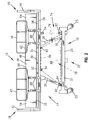
- a hospital bed 10 is illustrated as including the obstacle detection device 12 of the present invention.
- the hospital bed 10 includes opposing right and left longitudinal side edges 14 and 16 extending between a head end 18 and a foot end 20.
- the phrases "right side” and “left side” will be utilized to denote the relative location of an object positioned to lie nearest the right side edge 14 and left side edge 16, respectively, of the bed 10.
- the phrase "head end” will be utilized to denote the relative location of an object positioned to lie nearest the head end 18 of the hospital bed 10.
- the phrase “foot end” will be used to denote the proximate location of a referenced object positioned to lie nearest the foot end 20 of the hospital bed 10.
- the hospital bed 10 includes a base module 22 having a base frame 24 supported by conventional casters 25 which provide mobility to the bed 10.
- the base frame 24 includes a right side member 21 and a left side member 23 connected by a foot end cross member 29 and a head end cross member 31.
- An intermediate or elevating frame 26 is coupled to the base frame 24 by first and second pairs of lift arms 28 and 30 in a manner providing for vertical movement of the elevating frame 26 relative to the base frame 24.
- An articulating deck 36 is supported for movement relative to the elevating frame 26.
- a mattress 38 is carried by the articulating deck 36 and provides a sleeping or patient support surface 40 configured to receive a patient.
- a headboard 42 is illustratively supported by the elevating frame 26 proximate the head end 18 of the bed 10 while a footboard 44 is supported by the elevating frame 26 proximate the foot end 20 of the bed. It should be appreciated that the headboard 42 and the footboard 44 may alternatively be coupled to the base frame 24.
- Conventional first and second siderails 46 and 47 are provided proximate the longitudinal side edges 14 and 16 of the bed 10. The first siderails 46 are positioned proximate the foot end 20 of the bed 10, while the second siderails 47 are positioned proximate the head end 18 of the bed 10.
- a pair of arms 48 and 49 couple each of the siderails 46 and 47 to the articulating deck 36 in a manner providing for relative vertical movement therebetween.
- the articulating deck 36 includes a head section 50, a seat section 52, a thigh section 54, and a foot section 56.
- the first siderails 46 are supported by the foot section 56
- the second siderails 47 are supported by the head section 50.
- the siderails 46 and 47 move relative to each other as the foot section 56 and the head section 50 of the articulating deck 36 move relative to each other.
- the mattress 38 rests on the articulating deck 36 and includes a head portion 58, a seat portion 60, a thigh portion 62, and a foot portion 64, each of which generally correspond to the like-named portions of the deck 36, and each of which is generally associated with the head, seat, thighs, and feet of a patient supported on the surface 40.
- Details of the articulating deck 36 are of conventional design and may comprise those of the type disclosed in U.S. Patent No. 6,336,235 to Ruehl , which is assigned to the assignee of the present invention.
- the lift arms 28 and 30 are operably connected to a drive or lifting device 66 ( Fig. 4 ) for causing the vertical movement of the elevating frame 26 relative to the base frame 24. More particularly, the elevating frame 26 is configured to move vertically between a raised position ( Fig. 5 ) and a lowered position ( Fig. 6 ). A plurality of intermediate positions ( Fig. 7 ) are available for the elevating frame 26 between the raised position and the lowered position.
- the lifting device 66 may comprise a conventional mechanism of the type disclosed in U.S. Patent No. 3,958,383 to Adams et al . or U.S. Patent No. 6,336,235 to Ruehl , both of which are assigned to the assignee of the present invention.
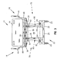
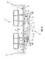
- the obstacle detection device 12 of the present invention includes a first or right side detection unit 70, associated with the right side longitudinal edge 14 of the hospital bed 10, a second or left side detection unit 72 associated with the left longitudinal side edge 16 of the bed 10, and a third or foot end detection unit 74 associated with the foot end 20 of the bed 10.
- the right side detection unit 70 is configured to generate a first optical curtain 76 ( Fig. 2 ) while the left side detection unit 72 is configured to generate a second optical curtain 78 substantially identical to the first optical curtain 76.
- the foot end detection unit 74 is configured to generate a third optical curtain 80 ( Fig. 3 ).
- a fourth or head end detection unit (not shown) substantially identical to the foot end detection unit 74 may likewise be provided adjacent the head end 18 of the bed 10 for generating a fourth optical curtain (not shown) similar to the optical curtains 76, 78, and 80.
- each detection unit 70, 72, and 74 includes an emitter 82 coupled to the base frame 24.
- the emitter 82 illustratively comprises a light source, such as an infrared (IR) light emitting diode (LED).
- IR infrared
- LED light emitting diode
- the light emitting diode may be empirically selected based upon dimensions and operating conditions of the bed 10.
- an emitting diode Model No. SFH-41SU available from OSRAM Opto Semiconductors of San Jose, California may be utilized.
- other conventional emitters including ultrasonic, radar, and microwave may be substituted for the infrared emitters.
- a beam shaping lens 84 is positioned adjacent to each emitter 82 for converting or shaping a beam of light emitted from the emitter 82 into the respective optical curtain 76, 78, 80.
- the beam shaping lens 84 may comprise a fresnel lens of the type well-known in the art. Illustratively, Model No. H43796 available from Edmund Scientific of Tonawanda, New York, may be utilized. It should be noted that a plurality of emitters 82 may be utilized to form each respective optical curtain 76, 78, 80, thereby eliminating the beam shaping lens 84.
- each respective emitter 82 and lens 84 define a perimeter including a predetermined width and height for the optical curtains 76, 78, and 80.
- the predetermined height is defined to extend from an upper edge 86 to a lower edge 88 intermediate the base frame 24 and the elevating frame 26.
- the predetermined height is equal to the distance between the base frame 24 and the elevating frame 26 when the elevating frame 26 is in its uppermost position ( Fig. 5 ) as defined by the lifting device 66.
- a plurality of detectors 90, 92, 94 are associated with each emitter 82 and are configured to receive or detect the respective optical curtain 76, 78, and 80.
- the detectors 90, 92, and 94 are identified as Detector A, Detector B, and Detector C, respectively in Fig. 4 .
- each optical curtain 76, 78, 80 is illustratively formed by a plurality of individual wireless infrared signals 96 ( Figs. 5-8 ) emitting from the emitter 82 and detectable by the detectors 90, 92, 94.
- BPW-34F from OSRAM Opto-Semiconductors of San Jose, California, may be used for detectors 90, 92, 94.
- detectors 90, 92, 94 may be used for detectors 90, 92, 94.
- detectors which are operable independently of an emitter such as proximity sensors or cameras, may be substituted for the combined infrared detectors 90, 92, 94 and emitters 82.
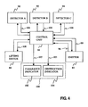
- a control unit 98 is provided in communication with each emitter 82 and detector 90, 92, 94.
- each emitter 82 transmits randomly modulated wireless infrared light rays or signals 96 to form a respective optical curtain 76, 78, 80.
- a source modulation or verification signal 99 is then transmitted through a conventional communication link, such as hard wires (not shown) disposed within the bed base frame 24, to the control unit 98. If the intensity, spectrum or modulation of the received wireless signal 96 at the detector 90, 92, 94 does not match the verification signal 99, the control unit 98 inhibits movement of the bed 10 by the lifting device 66. As such, the verification signal 99 prevents external light sources, such as room lights or sunlight, from interfering with the operation of the obstacle detection device 12.
- An indicator 100 may be supported by the hospital bed 10 for providing an indication of the detection of the optical curtain 76, 78, 80 by the detectors 90, 92, 94. More particularly, the indicator 100 may include a clearance indicator, illustratively in the form of a green light 102, which is activated by a clearance signal 103 supplied by the control unit 98 to provide an indication of a clear detection path between the emitter 82 and the detectors 90, 92, 94. An obstruction indicator, illustratively in the form of a red light 104, may be provided to indicate a failure of one of the detectors 90, 92, 94 to receive the appropriate wireless signal 96 of the optical curtains 76, 78, 80.
- the obstruction indicator 104 is activated by an obstruction signal 105 supplied by the control unit 98. It should be appreciated that the indicator 100 may comprise a single bi-color red/green status indicator. Alternatively, other indicators, such as an audible alarm or any other device which may provide an indication of the presence of an obstacle in the detection path, may be readily substituted for the obstruction indicator light 104.
- the process begins at block 202 upon activation of the obstacle detection device 12.
- the process continues to block 204 where the respective emitters 82 are activated.
- the optical curtains 76, 78, 80 are formed by passing a light beam containing rays or signals 96 produced by the respective emitters 82 through the associated beam shaping lenses 84.
- the respective receivers 90, 92, 94 are activated.
- the receivers 90, 92, 94 determine whether the respective wireless curtain 76, 78, 80 is detected. If the curtain 76, 78, 80 is detected, then the process continues to block 212 where vertical movement of the elevating frame is permitted by the control unit 98.
- the clearance indicator 102 is activated in response to the clearance signal 103 supplied by the control unit 98.
- the respective detector 90, 92, 94 sends an interruption signal 106 to the control unit 98.
- the process continues to block 216 where the control unit 98 generates a stop signal 108.
- the elevating frame lifting device 66 is deactivated in response to the stop signal 108.
- the obstruction indicator 104 is activated in response to the obstruction signal 105 supplied by the control unit 98.
- Fig. 5 illustrates the hospital bed 10 in a fully raised position. Moreover, the elevating frame 26 is raised to its uppermost position by the lifting device 66 coupled to the lift arms 28, 30.
- Fig. 6 illustrates the elevating frame 26 of the hospital bed 10 in its lowermost position wherein the elevating frame 26 is lowered to its position nearest the base frame 24 through operation of the lifting device 66 and the lift arms 28, 30, 32, 34.
- Fig. 7 illustrates the hospital bed 10 with the elevating frame 26 in a intermediate position between the uppermost position of Fig. 5 to the lowermost position of Fig. 6 .
- the lifting device 66 may be provided with position sensors (not shown) configured to provide feedback position signals to the control unit 98 providing an indication of the relative vertical position of the elevating frame 26.
- position sensors are well-known in the art and may be utilized with the obstacle detection device 12 of the present invention to prevent the elevating frame 26 from moving outside of the range of the optical curtains 76, 78 and 80.
- the receivers 90, 92, 94 for each optical curtain 76, 78, 80 are configured to receive wireless signals 96 making up or forming the respective curtains 76, 78, 80.
- the wireless signals 96 travel along a plurality of detection paths from the emitter 82 to the receivers 90, 92, 94.
- Representative wireless signals 96a, 96b, 96c, 96d and 96e are illustrated in Figs. 5 and 8 .
- Potential obstacles are represented by reference numerals 114, 116 and 118 in Fig. 5 and are placed within the respective detection paths of signals 96a, 96c, and 96e.
- the obstacles 114, 116, 118 prevent the wireless signals 96a, 96c, and 96e of the optical curtains 78 and 80 from reaching the respective detectors 90, 92, 94.
- the obstacles 114, 116, 118 may comprise a person, medical instruments or any other object found within a hospital room.
- Figs. 10 and 11 illustrate a hospital bed 310 including an alternative embodiment obstacle detection device 312 of the present invention.
- the obstacle detection device 312 includes a first or right side detection unit 370 associated with the right longitudinal side edge 14 of the hospital bed 310, a second or left side detection unit 372 associated with the left longitudinal side edge 16 of the bed 310, and a third or foot end detection unit 374 associated with the foot end 20 of the bed 310.
- the right side detection unit 370 is configured to generate a first optical curtain 376
- the left side detection unit 372 is configured to generate a second optical curtain 378.
- the foot end detection unit 374 is configured to generate a third optical curtain 380.
- a fourth or head end detection unit may be provided adjacent the head end 18 of the bed 310 for generating a fourth optical curtain (not shown) similar to the optical curtains 376, 378, and 380.
- each detection unit 370, 372, and 374 of the obstacle detection device 312 includes a first or lower support 326 including a plurality of spaced apart emitters 328.
- Each emitter 328 preferably comprises a self-contained infrared light-emitting diode.
- the emitters produce a beam of light 330 upwardly toward the elevating frame of the bed 10.
- each beam of light 330 is discrete and spaced apart from adjacent beams of light 330.
- the plurality of beams of light 330 define the respective optical curtains 376, 378, and 380.
- Each detection unit 370, 372, and 374 of the optical detection device 312 further includes a second or upper support 332 including a plurality of detectors 334.
- Each detector 334 is associated with one of the emitters 328 and is configured to receive or detect the respective light beam 330 defining the optical curtains 376, 378, and 380.
- control unit 98 prevents the lifting device 66 from vertically moving the elevating frame 26.
- the optical curtains 376, 378, and 380 of the obstacle detection device 312 require that the light beams 330 be accurately aligned between the emitters 328 and the detectors 334 throughout the full path of travel of the elevating frame 26. It may be appreciated, non-linear movement of the elevating frame 26 relative to the base frame 24 may cause the respective emitters 328 and detectors 334 to become mis-aligned, thereby resulting in a signal to the control unit 98 that an obstacle is positioned within the optical curtain 376, 378, 380. Such false optical detection signals are less likely to occur using the earlier embodiment having substantially uniform optical curtains 76, 78, 80.
- the individual detection units 370, 372, and 374 of the obstacle detection device 312 may comprise the EASY-GUARDTM grid system available from Banner Engineering Corp. of Minneapolis, Minnesota. However, it should be appreciated that other similar devices may be substituted therefor.
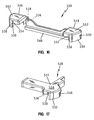
- FIGs. 12 and 13 illustrate portions of a hospital bed 410 including a further illustrative embodiment obstacle detection device 412 of the present invention.
- the obstacle detection device 412 includes a first or right side detection unit 470 associated with the right longitudinal side edge 14 of the hospital bed 410, a second or left side detection unit 472 associated with the left longitudinal side edge 16 of the bed 310, and a third or foot end detection unit 474 associated with the foot end 20 of the bed 310.
- the right side detection unit 470 is configured to detect an obstacle proximate the top of the right side member 21 of the base frame 24, while the left side detection unit 472 is configured to detect an obstacle along the top of the left side 23 of the base frame 24.
- the foot end detection unit 474 is configured to detect an obstacle in front of the foot end cross member 29 of the base frame 24 at the foot end 20 of the bed 410. It should be appreciated that a fourth or head end detection unit (not shown) may be provided adjacent the head end 18 of the bed 410 for detecting an obstacle behind the head end cross member 31 of the base frame 24 of the bed 410.
- each detection unit 470, 472, 474 of the obstacle detection device 412 includes an emitter 482a, 482b, 482c and an associated detector 490a, 490b, 490c.
- Each emitter 482 illustratively comprises a self-contained infrared (IR) light-emitting diode (LED) 483 coupled to an emitter microprocessor 485 which generates an infrared (IR) signal that is configured to be received by the associated detector 490.
- the microprocessor 485 illustratively comprises a conventional eight-bit microprocessor and may comprise Part No. MC68HC908QT1CDW available from Motorola of Schaumburg, Illinois.
- a voltage regulator 487 is used to interface the microprocessor 485 to an 8.2 volt input provided by the power source 488 of a power supply module 489.
- the output of the microprocessor 485 interfaces with the LED 483, which converts the electrical signal into an optical one.
- the detector 490 includes an IR sensor 491 which is configured to receive the optical signal emitted from the emitter 482 and convert the optical signal to an electrical signal.
- the sensor 491 is an infrared photo diode configured to observe a specific signal frequency and may comprise infrared detector Part No. GP1UM267XK available from Sharp Microelectronics of Camas, Washington.
- the IR sensor 491 is interfaced to the 8.2 volt power source 488 via a conventional regulator 492.
- the output of the detector 490 is routed through a buffer 493 and to the power supply module 489 for processing in the manner described herein.
- illustrative emitters 482 and detectors 490 utilize infrared light
- other wireless signals may be substituted therefore. More particularly, other forms of electromagnetic radiation, such as ultrasonic, radar, and microwave, may be substituted for IR light.
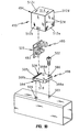
- each emitter 482 and detector 490 is received within a housing 494.
- Each housing 494 includes a cover 495 coupled to a base 498.
- the base 498 includes a mounting aperture 500 configured to receive a fastener 502 for securing the base 498 to an aperture 503 formed in the base frame 24 of the bed 410.
- a locating peg 504 extends downwardly from a lower surface of the base 498 and is configured to be received within an aperture 506 formed in the base frame 24 of the bed 410.
- the base 498 further includes four side walls 508 having a pair of notches or slots 510 formed in a pair of opposing ones of the side walls 508b and 508d.
- the cover 496 includes four side walls 512 and a top wall 514.
- a pair of locking tabs 516 are resiliently supported by an opposing pair of the side walls 512b and 512d and are configured to lockingly engage with the notches 510 of the base 498.
- Cooperating slots 518 and 520 are formed within the cover 496 and base 498 and are configured to receive components, as supported on a circuit board 522, of the respective emitter 482 and detector 490.
- a pair of apertures 524 are formed within one of the side walls 512a of the cover 496 and are aligned with the LED 483 of the emitter 482 or the sensor 491 of the detector 490.
- the apertures 524 are positioned and sized for the efficient transmission of infrared light without incurring substantial interference from external light sources.
- the apertures 524 have a diameter of 3.18 millimeters (.125 inches) and are positioned approximately 24.2 mm (.953 inches) in front of the mounting slots 518 and 520 for the respective circuit board 522.
- each head end frame cover 526 and 528 includes a housing 531 having side walls 532 connected to a top wall 534.
- One of the side walls 532 includes an opening 536 aligned with one of the apertures 524 in one of the housings 494 associated with the right and left side detection units 470 and 472.
- a transparent window 538 illustratively a clear thermoplastic material, is fixed within the opening 536 to prevent the passage of fluid therethrough, while permitting the passage of infrared light from the emitter 482 to the detector 490.
- the window 538 may be fixed in place using conventional methods, such as ultrasonic welding or adhesives.
- a clearance slot 540 may be formed in another one of the side walls 532 of the frame covers 526 and 528 to provide clearance for the brake/steer pedals 542 of the hospital bed 410, as needed.
- the foot end frame cover 530 includes first and second housings 544 and 546 coupled together by a connecting member 548.
- Each housing 544 and 546 includes side walls 550 coupled to a top wall 552, and a pair of openings 554 and 556 formed within different ones of the side walls 550.
- the openings 554 are associated with one of the apertures 524 of the foot end housings 494 of the right and left side detection units 470 and 472.
- the openings 556 are associated with one of the apertures 524 of the housings 494 associated with the foot end detection unit 474.
- Windows 538 are illustratively fixed within the openings 554 and 556 as detailed above.
- the right and left side detection units 470 and 472 may have their emitters 482 positioned at the head end 18 and foot end 20 of the hospital bed 410, respectively.
- the transmission of infrared light from the emitters 482 of the right side detection unit 470 and the left side detection unit 472 will be in opposite directions (as shown by arrows 557 in Fig. 13 ) in order to reduce the possibility of cross talk between the two detection units 470 and 472.
- the emitter 482 of the foot end detection unit 474 does not direct infrared light toward the detectors 490 of the right and left side detection units 470 and 472.
- a controller or microprocessor 558 of the power supply module 489 initializes the various parameters and disables all interrupts.
- the power source 488 of the power supply module 489 supplies each emitter 482 with the required power of 8.2 volts.
- the microprocessor 485 of each emitter 482 is used to cause the LED 483 to generate an IR pulse signal 560 of the type illustrated in Fig. 22 .
- the signal 560 includes a 600 microsecond pulsed portion 561 having a 57 kHz signal with a 50 percent duty cycle. A two millisecond delay follows the 57 kHz pulse with the output low. Such a pulse sequence repeats indefinitely.
- An internal bus clock (not shown) illustratively runs at 3.2 MHz. As such, this provides an instruction cycle time of 312.5 nanoseconds.
- the detector 490 is configured to look for a 56.8 kHz signal, which translates into 17.66 microseconds per pulse, or 8.803 microseconds per state.
- the number of instruction cycles is determined to be 28.17.
- Using 28 cycles per state provides a total pulse time of 17.5 microseconds which equates to 57.14 kHz.
- a loop that generates the 57 kHz IR signal is run 34 times, thereby giving a total time of 595 microseconds.
- the detector 490 is configured to look for the pulse signal 560 including a pulsed portion or an IR signal burst 561 at a specific frequency. When the signal 560 is detected with the appropriate frequency component, the output of the detector 490 becomes active, effectively demodulating the transmitted signal.
- the detector 490 includes a built-in frequency filter having a range of 53.6 kHz to 60 kHz (56.8 ⁇ 3.2 kHz).
- the IR detector 490 adjusts its sensitivity level proportionately to the strength of the incident light signal. This helps further filter noise signals that may be present in the 56.8 kHz range.
- the IR detector 490 filters the incident light to allow only the wave length associated with IR to come into contact with the internal photo diode or sensor 491. This helps filter out the effects of sunlight, incandescent lighting, and fluorescent lights.
- the detector 490 Upon detecting the appropriate wave length or frequency pulse signal 560, the detector 490 provides an essentially demodulated signal 562 such as that illustrated in Fig. 23 .
- the signal illustratively has a high value of approximately 5 volts.
- the demodulated signal 562 from the detector 490 is then transmitted to a Resistor-Capacitor (RC) filter 564 comprising part of the power supply module 489.
- the RC filter 564 converts the signal 562 of Fig. 23 to a waveform 566 such as that illustrated in Fig. 24 .
- the waveform of Fig. 24 has a nominal value of approximately 3.8 volts ⁇ 0.5 volts.
- the RC filter 564 is of conventional design and includes a 100 kohm resistor and a 0.1 ⁇ F capacitor.
- the output from the RC filter 564 passes through a conventional analog to digital (A/D) converter (not shown) on its way to the microprocessor 558.
- A/D analog to digital
- the microprocessor 558 functions by activating an indicator 100 and disabling the lifting device 66 from further lowering of the patient support as detailed herein.
- each emitter 482 and detector 490 could be configured to send and receive signal waveforms having different bit or pulse patterns, including different pulse frequencies and pulse durations, in order to further limit the possibility of cross talk between different emitters and detectors.
- the detectors 490 are configured to detect a frequency rather than an intensity, interference from external light sources is reduced.
- similar emitters 482 and detectors 490 may be used for obstacle detection for a wide range of distances between the respective emitters 482 and detectors 490.
Landscapes
- Health & Medical Sciences (AREA)
- Life Sciences & Earth Sciences (AREA)
- Animal Behavior & Ethology (AREA)
- General Health & Medical Sciences (AREA)
- Public Health (AREA)
- Veterinary Medicine (AREA)
- Nursing (AREA)
- Engineering & Computer Science (AREA)
- Mechanical Engineering (AREA)
- Oral & Maxillofacial Surgery (AREA)
- Biomedical Technology (AREA)
- Dentistry (AREA)
- Rehabilitation Therapy (AREA)
- Physics & Mathematics (AREA)
- Biophysics (AREA)
- Pathology (AREA)
- Physiology (AREA)
- Heart & Thoracic Surgery (AREA)
- Medical Informatics (AREA)
- Molecular Biology (AREA)
- Surgery (AREA)
- Invalid Beds And Related Equipment (AREA)
- Accommodation For Nursing Or Treatment Tables (AREA)
- Organic Low-Molecular-Weight Compounds And Preparation Thereof (AREA)
- Measuring And Recording Apparatus For Diagnosis (AREA)
Claims (16)
- Hindernisdetektorgerät (12, 312, 412) zum Einsatz bei einem Krankenhausbett (10, 310, 410) mit einem Grundrahmen (24) und einem mit einer Patientenunterstützungsfläche (40) verbundenen Hubrahmen (26), wobei das Hindernisdetektorgerät die Bewegung des Hubrahmens (26) relativ zum Grundrahmen (24) steuert, sobald innerhalb eines Verstellweges des Hubrahmens (26) ein Hindernis erfasst wird, und wobei das Hindernisdetektorgerät Detektorvorrichtungen (90, 92, 94, 334, 490a, 490b, 490c) zur Erzeugung eines entsprechenden Ausgangssignals und Vorrichtungen (98) zum Empfang des Signals und zur Steuerung der entsprechenden Bewegung des Hubrahmens (26) umfasst,
dadurch gekennzeichnet, dass das Hindernisdetektorgerät (12, 312, 412) mit Vorrichtungen (82, 328, 482a, 482b, 482c) zur Herstellung eines Funkvorhangs (76, 78, 80, 376, 378, 380) innerhalb eines Verstellweges des Hubrahmens (26) versehen ist, wobei die Detektorvorrichtungen den Funkvorhang (76, 78, 80, 376, 378, 380) erfassen. - Gerät nach Anspruch 1, wobei die Generatorvorrichtung einen Generator zur Herstellung eines optischen Vorhangs (82, 328, 482a, 482b, 482c) umfasst, die Detektorvorrichtung mit einem Detektor zur Erfassung des optischen Vorhangs (90, 92, 94, 334, 490a, 490b, 490c) versehen ist und die Steuervorrichtung eine mit dem Detektor (90, 92, 94, 334, 490a, 490b, 490c) verbundene Steuereinheit aufweist, wobei die Steuereinheit (98) so konfiguriert ist, dass sie bei Nichterfassung des optischen Vorhangs (76, 78, 80, 376, 378, 380) durch den Detektor (90, 92, 94, 334, 490a, 490b, 490c) eine relative Bewegung zwischen Grundrahmen (24) und Hubrahmen (26) verhindert.
- Hindernisdetektorgerät nach Anspruch 1, wobei die Generatorvorrichtung einen entweder mit dem Grundrahmen (24) oder dem Hubrahmen (26) des Betts (10, 310, 410) verbundenen Emitter (82, 328, 482a, 482b, 482c) umfasst, wobei der Emitter (82, 328, 482a, 482b, 482c) so konfiguriert ist, dass ein sich bis unterhalb des Hubrahmens erstreckender Funkvorhang (76, 78, 809, 376, 378, 380) hergestellt wird, wobei die Detektorvorrichtung einen mit entweder dem Grundrahmen (24) oder dem Hubrahmen (26) des Betts (10, 310, 410) verbundenen Empfänger (90, 92, 94, 334, 490a, 490b, 490c) aufweist und wobei zur Steuervorrichtung eine Steuereinheit (98) gehört, die mit dem Empfänger (90, 92, 94, 334, 490a, 490b, 490c) in Verbindung steht.
- Hindernisdetektorgerät nach Anspruch 3, wobei der Emitter eine Infrarot-Lichtquelle (82, 328, 482a, 482b, 482c) aufweist und der Funkvorhang einen optischen Vorhang umfasst.
- Hindernisdetektorgerät nach Anspruch 4, mit des Weiteren einer Linse (84), die in der Nähe der Infrarot-Lichtquelle (82) angeordnet und so konfiguriert ist, dass von der Infrarot-Lichtquelle emittiertes Licht in den optischen Vorhang umgewandelt wird.
- Hindernisdetektorgerät nach Anspruch 5, wobei die Linse eine Fresnel-Linse (84) umfasst.
- Hindernisdetektorgerät nach irgendeinem der Ansprüche 3 bis 6, wobei der Funkvorhang ein moduliertes Signal umfasst und wobei der Empfänger (490) das modulierte Signal mit einem vorbestimmten Verifizierungssignal vergleicht, um eine Störung durch externe Lichtquellen zu verhindern.
- Hindernisdetektorgerät nach irgendeinem der Ansprüche 3 bis 7, wobei der Empfänger (90, 92, 94, 334, 490a, 490b, 490c) so konfiguriert ist, dass er sich zusammen mit dem Hubrahmen (26) innerhalb eines vorbestimmten vertikalen Bereichs bewegt.
- Hindernisdetektorgerät nach Anspruch 8, wobei der vorbestimmte vertikale Bereich sich vom Grundrahmen (24) bis zum Hubrahmen (26) erstreckt, wenn sich der Hubrahmen (26) in einer voll angehobenen Stellung befindet.
- Hindernisdetektorgerät nach irgendeinem der Ansprüche 3 bis 9, mit des Weiteren einer mit der Steuereinheit (98) verbundenen Anzeige (100), wobei die Anzeige (100) so konfiguriert ist, dass sie anzeigt, wenn vom Empfänger (90, 92, 94, 334, 490a, 4390b, 490c) der Funkvorhang (76, 78, 80, 376, 378, 380) nicht erfasst wird.
- Hindernisdetektorgerät nach Anspruch 10, wobei die Anzeige (100) eine Beleuchtung umfasst.
- Hindernisdetektorgerät nach Anspruch 10, wobei die Anzeige (100) einen akustischen Alarm umfasst.
- Hindernisdetektorgerät nach irgendeinem der Ansprüche 3 bis 12, wobei die Steuereinheit einen Prozessor (558) umfasst, der mit einem Stellantrieb (66) in Verbindung steht, welcher so konfiguriert ist, dass der Hubrahmen (26) relativ zum Grundrahmen (24) bewegt wird.
- Hindernisdetektorgerät nach irgendeinem der Ansprüche 3 bis 12, wobei die Steuereinheit ein Steuerrelais umfasst, das mit einem Stellantrieb (66) in Verbindung steht, welcher so konfiguriert ist, dass der Hubrahmen (26) relativ zum Grundrahmen (24) bewegt wird.
- Hindernisdetektorgerät nach irgendeinem der Ansprüche 3 bis 14, wobei der Emitter (328) eine Vielzahl von Funksignalen in einer Vielzahl von Signalwegen erzeugt, wobei eine Vielzahl von Empfängern (334) so konfiguriert sind, dass die Funksignale entlang verschiedenen Signalwegen erfasst werden, und wobei die Steuereinheit (98) die Bewegung des Hubrahmens (26) relativ zum Grundrahmen (24) verhindert, wenn von einem der Empfänger ein Funksignal nicht erfasst wird.
- Hindernisdetektorgerät nach irgendeinem der Ansprüche 3 bis 15, wobei vom Empfänger (90, 92, 94, 334, 490a, 490b, 490c) das Ausgangssignal erzeugt wird, wenn vom Empfänger (90, 92, 94, 334, 490a, 490b, 490c) der Funkvorhang (76, 78, 80, 376, 378, 380) nicht erfasst wird.
Priority Applications (2)
| Application Number | Priority Date | Filing Date | Title |
|---|---|---|---|
| EP20100011366 EP2319473A3 (de) | 2002-04-19 | 2003-04-21 | Einrichtung für Spitalbetten zur Wahrnehmung von Hindernissen und Verfahren |
| EP20090002423 EP2055286B1 (de) | 2002-04-19 | 2003-04-21 | Einrichtung für Spitalbetten zur Wahrnehmung von Hindernissen |
Applications Claiming Priority (5)
| Application Number | Priority Date | Filing Date | Title |
|---|---|---|---|
| US37381902P | 2002-04-19 | 2002-04-19 | |
| US373819P | 2002-04-19 | ||
| US40869802P | 2002-09-06 | 2002-09-06 | |
| US408698P | 2002-09-06 | ||
| PCT/US2003/012166 WO2003088885A1 (en) | 2002-04-19 | 2003-04-21 | Hospital bed obstacle detection device and method |
Related Child Applications (2)
| Application Number | Title | Priority Date | Filing Date |
|---|---|---|---|
| EP20090002423 Division EP2055286B1 (de) | 2002-04-19 | 2003-04-21 | Einrichtung für Spitalbetten zur Wahrnehmung von Hindernissen |
| EP20100011366 Division EP2319473A3 (de) | 2002-04-19 | 2003-04-21 | Einrichtung für Spitalbetten zur Wahrnehmung von Hindernissen und Verfahren |
Publications (2)
| Publication Number | Publication Date |
|---|---|
| EP1496830A1 EP1496830A1 (de) | 2005-01-19 |
| EP1496830B1 true EP1496830B1 (de) | 2009-03-11 |
Family
ID=29254537
Family Applications (3)
| Application Number | Title | Priority Date | Filing Date |
|---|---|---|---|
| EP20090002423 Expired - Lifetime EP2055286B1 (de) | 2002-04-19 | 2003-04-21 | Einrichtung für Spitalbetten zur Wahrnehmung von Hindernissen |
| EP03721786A Expired - Lifetime EP1496830B1 (de) | 2002-04-19 | 2003-04-21 | Einrichtung für spitalbetten zur wahrnehmung von hindernissen |
| EP20100011366 Withdrawn EP2319473A3 (de) | 2002-04-19 | 2003-04-21 | Einrichtung für Spitalbetten zur Wahrnehmung von Hindernissen und Verfahren |
Family Applications Before (1)
| Application Number | Title | Priority Date | Filing Date |
|---|---|---|---|
| EP20090002423 Expired - Lifetime EP2055286B1 (de) | 2002-04-19 | 2003-04-21 | Einrichtung für Spitalbetten zur Wahrnehmung von Hindernissen |
Family Applications After (1)
| Application Number | Title | Priority Date | Filing Date |
|---|---|---|---|
| EP20100011366 Withdrawn EP2319473A3 (de) | 2002-04-19 | 2003-04-21 | Einrichtung für Spitalbetten zur Wahrnehmung von Hindernissen und Verfahren |
Country Status (7)
| Country | Link |
|---|---|
| US (6) | US7472437B2 (de) |
| EP (3) | EP2055286B1 (de) |
| AT (1) | ATE424798T1 (de) |
| AU (1) | AU2003225079A1 (de) |
| CA (1) | CA2482462A1 (de) |
| DE (1) | DE60326558D1 (de) |
| WO (1) | WO2003088885A1 (de) |
Cited By (1)
| Publication number | Priority date | Publication date | Assignee | Title |
|---|---|---|---|---|
| CN110946722A (zh) * | 2018-09-27 | 2020-04-03 | 希尔-罗姆服务公司 | 障碍物检测红外光束滤波器 |
Families Citing this family (62)
| Publication number | Priority date | Publication date | Assignee | Title |
|---|---|---|---|---|
| US6212714B1 (en) | 1995-01-03 | 2001-04-10 | Hill-Rom, Inc. | Hospital bed and mattress having a retracting foot section |
| AU2744701A (en) | 1999-12-29 | 2001-07-09 | Hill-Rom Services, Inc. | Hospital bed |
| ATE424798T1 (de) | 2002-04-19 | 2009-03-15 | Hill Rom Services Inc | Einrichtung für spitalbetten zur wahrnehmung von hindernissen |
| EP2181685B1 (de) | 2002-09-06 | 2014-05-14 | Hill-Rom Services, Inc. | Krankenbett mit einer geregelten aufblasbaren Auflage |
| DE20319312U1 (de) | 2003-12-12 | 2005-05-04 | Dewert Antriebs- Und Systemtechnik Gmbh & Co. Kg | Möbel |
| US7411174B2 (en) * | 2004-10-12 | 2008-08-12 | Eash Brandon A | Sensor-controlled LED array apparatus and method |
| GB0506691D0 (en) * | 2005-04-01 | 2005-05-11 | Pegasus Ltd | Height-adjustable bed |
| DE102005015795B4 (de) * | 2005-04-06 | 2008-02-14 | Siemens Ag | Geräteschutz für Hubeinheit |
| US8823519B2 (en) * | 2005-06-08 | 2014-09-02 | C-Dax Limited | Pasture management |
| EP1906794A4 (de) * | 2005-07-08 | 2014-05-07 | Hill Rom Services Inc | Steuereinheit für patientenstütze |
| DK1951111T3 (da) * | 2005-11-07 | 2010-11-22 | Stryker Corp | Patienthåndteringsanordning med visning af lokal status, one-touch fowler-vinkelindstilling og aktiveringsalarmopsætning |
| DE602006014295D1 (de) * | 2005-11-09 | 2010-06-24 | Hill Rom Services Inc | Luftventilanordnung für eine patientenstütze |
| ATE546120T1 (de) * | 2006-04-27 | 2012-03-15 | Linak As | Bett, vorzugsweise krankenhaus- oder pflegebett |
| DE102007018694B4 (de) | 2007-04-18 | 2009-04-09 | Dr. Ing. H.C. F. Porsche Aktiengesellschaft | Bett sowie ein Verfahren zur Steuerung bzw. Sichheitsvorrichtung für ein Bett |
| DE102007018693A1 (de) | 2007-04-18 | 2008-10-23 | Dr. Ing. H.C. F. Porsche Aktiengesellschaft | Vorrichtung zur Bewegung, insbesondere zur Hubbewegung, von Lasten |
| US8039766B2 (en) * | 2009-09-15 | 2011-10-18 | Hill-Rom Services, Inc. | Obstruction detecting force sensing system wherein the threshold force value for detecting an obstruction is set according to the configuration of the bed |
| US8442738B2 (en) * | 2009-10-12 | 2013-05-14 | Stryker Corporation | Speed control for patient handling device |
| EP2338456A1 (de) * | 2009-12-22 | 2011-06-29 | Invacare International Sàrl | Verfahren zur Sicherung des Anhebebetriebs eines Rollstuhlsitzes und Anhebevorrichtung für einen Rollstuhl |
| US8350709B2 (en) * | 2010-03-31 | 2013-01-08 | Hill-Rom Services, Inc. | Presence detector and occupant support employing the same |
| US8266741B2 (en) | 2010-08-10 | 2012-09-18 | Hill-Rom Services, Inc. | Bed movement cessation based on IV pump alarm |
| US9204823B2 (en) * | 2010-09-23 | 2015-12-08 | Stryker Corporation | Video monitoring system |
| US8959681B2 (en) * | 2010-12-20 | 2015-02-24 | Hill-Rom Services, Inc. | Ground sensor control of foot section retraction |
| WO2013077288A1 (ja) | 2011-11-22 | 2013-05-30 | パラマウントベッド株式会社 | ベッド装置 |
| WO2013086620A1 (en) * | 2011-12-16 | 2013-06-20 | Chg Hospital Beds Inc. | Patient support overload or obstruction detection |
| KR101366543B1 (ko) * | 2012-01-26 | 2014-02-26 | 삼성메디슨 주식회사 | 캐스터 상태 표시 장치 |
| WO2013123119A1 (en) * | 2012-02-15 | 2013-08-22 | Stryker Corporation | Patient support apparatus and controls therefor |
| US10123923B2 (en) * | 2012-02-21 | 2018-11-13 | Sizewise Rentals, L.L.C. | Auto leveling low profile patient support apparatus |
| US9228885B2 (en) * | 2012-06-21 | 2016-01-05 | Hill-Rom Services, Inc. | Patient support systems and methods of use |
| US9259369B2 (en) * | 2012-09-18 | 2016-02-16 | Stryker Corporation | Powered patient support apparatus |
| WO2014201379A2 (en) * | 2013-06-15 | 2014-12-18 | Hill-Rom Services, Inc. | Adjustable person support system |
| US10188569B2 (en) | 2013-09-06 | 2019-01-29 | Stryker Corporation | Patient support usable with bariatric patients |
| US10130536B2 (en) | 2013-09-06 | 2018-11-20 | Stryker Corporation | Patient support usable with bariatric patients |
| EP2873400B1 (de) | 2013-11-18 | 2018-01-31 | Völker GmbH | Personentragevorrichtung |
| US9603764B2 (en) | 2014-02-11 | 2017-03-28 | Medline Industries, Inc. | Method and apparatus for a locking caster |
| AU2015229719B2 (en) | 2014-03-10 | 2017-04-06 | Stryker Corporation | Limb positioning system |
| CA3174039A1 (en) * | 2014-08-27 | 2016-02-27 | Umano Medical Inc. | Systems for patient support surface orientation and displacement |
| CA3226912A1 (en) * | 2014-10-17 | 2016-04-21 | Stryker Corporation | Person support apparatuses with motion monitoring |
| US9951904B2 (en) | 2015-03-24 | 2018-04-24 | Stryker Corporation | Rotatable seat clamps for rail clamp |
| AU2016270661B2 (en) | 2015-05-29 | 2021-04-22 | Hill-Rom Services, Inc. | Patient support apparatus |
| US11020297B2 (en) | 2015-12-22 | 2021-06-01 | Stryker Corporation | Powered side rail for a patient support apparatus |
| US10736803B2 (en) | 2016-02-26 | 2020-08-11 | Stryker Corporation | Lift assembly for patient support apparatus |
| US10842701B2 (en) | 2016-10-14 | 2020-11-24 | Stryker Corporation | Patient support apparatus with stabilization |
| BR112019010797A2 (pt) | 2016-11-28 | 2019-10-01 | Verb Surgical Inc | sistema cirúrgico robótico para reduzir vibração indesejada |
| US10499997B2 (en) | 2017-01-03 | 2019-12-10 | Mako Surgical Corp. | Systems and methods for surgical navigation |
| CN106901909B (zh) * | 2017-03-20 | 2018-04-10 | 韩先章 | 一种医疗病床 |
| US10987268B2 (en) | 2017-04-21 | 2021-04-27 | Stryker Corporation | Emergency cot with a litter height adjustment mechanism |
| US12472112B2 (en) | 2017-04-21 | 2025-11-18 | Stryker Corporation | Patient handling apparatus with hydraulic control system |
| US10987260B2 (en) | 2017-04-21 | 2021-04-27 | Stryker Corporation | Patient handling apparatus with hydraulic control system |
| US11090209B2 (en) | 2017-06-20 | 2021-08-17 | Stryker Corporation | Patient support apparatus with control system and method to avoid obstacles during reconfiguration |
| US11213443B2 (en) * | 2017-12-29 | 2022-01-04 | Stryker Corporation | Indication system to identify open space beneath patient support apparatus |
| USD909805S1 (en) * | 2018-02-15 | 2021-02-09 | Michael F. Kunde | Transfer bar |
| US11344228B2 (en) * | 2018-05-02 | 2022-05-31 | Wernher Ovalle | Patient monitoring device and system |
| US20190380896A1 (en) * | 2018-06-15 | 2019-12-19 | Andy Wang | Chair safety system against accidental pressing |
| EP3610840A1 (de) | 2018-08-14 | 2020-02-19 | Gymna Uniphy | Behandlungsliege mit sicherheitsverbesserung |
| CN109875781B (zh) * | 2019-04-23 | 2020-09-11 | 绍兴第二医院医共体总院(绍兴第二医院) | 一种医用多功能病床 |
| US12036161B2 (en) | 2019-08-16 | 2024-07-16 | Stryker Corporation | Patient support with deck width monitoring and control |
| US11583455B2 (en) | 2019-10-28 | 2023-02-21 | Stryker Corporation | Hydraulic valve and system |
| US11896531B2 (en) | 2019-10-28 | 2024-02-13 | Stryker Corporation | Hydraulic circuit for a patient handling apparatus |
| US11730650B2 (en) | 2019-12-30 | 2023-08-22 | Stryker Corporation | Patient support apparatus with hydraulic oscillation dampening |
| EP4221587B1 (de) | 2020-09-30 | 2026-01-07 | Stryker Corporation | Ausgangsdetektionssystem mit obstruktionsreaktion |
| CA3198221A1 (en) | 2022-04-28 | 2023-10-28 | Stryker Corporation | Patient support apparatus for treating patients presenting behavioral health indicia |
| SE2330508A1 (en) * | 2023-11-15 | 2025-09-03 | Arjo Ip Holding Ab | Patient handling device for raising and lowering a patient with an inclined anti-crush safety device |
Family Cites Families (65)
| Publication number | Priority date | Publication date | Assignee | Title |
|---|---|---|---|---|
| US1078077A (en) * | 1913-06-23 | 1913-11-11 | Nat Spring Bed Company | Bed. |
| US2527111A (en) * | 1947-10-07 | 1950-10-24 | Walter Brumbach | Vertically adjustable bed construction |
| US2900521A (en) * | 1953-07-21 | 1959-08-18 | Westinghouse Electric Corp | Door control apparatus |
| DE2007840C3 (de) | 1970-02-20 | 1979-11-15 | Endl, Alfons, 8000 Muenchen | Lichtschrankengitter |
| US3704396A (en) | 1971-05-12 | 1972-11-28 | Cincinnati Inc | Safety device for machines |
| US3951861A (en) * | 1971-06-14 | 1976-04-20 | Sumitomo Chemical Company, Limited | Catalysts for the preparation of acrolein |
| US3746863A (en) * | 1972-03-15 | 1973-07-17 | Exotron Ind Ltd | Light curtain control for a switch |
| DE2247053C3 (de) * | 1972-09-26 | 1979-08-09 | Erwin Sick Gmbh Optik-Elektronik, 7808 Waldkirch | Lichtschrankengitter |
| US4023887A (en) * | 1972-10-30 | 1977-05-17 | General Optimation, Inc. | Optical communication, switching and control apparatus and systems and modular electro-optical logic circuits, and applications thereof |
| SE372085B (de) * | 1973-02-27 | 1974-12-09 | L Svensson | |
| US3805061A (en) * | 1973-04-23 | 1974-04-16 | Tyco Laboratories Inc | Object detecting apparatus |
| US3970846A (en) * | 1973-10-29 | 1976-07-20 | Xenex Corporation | Presence detecting system with self-checking |
| US3958283A (en) | 1974-08-09 | 1976-05-25 | Hill-Rom Company, Inc. | Elevating and Trendelenburg mechanism for an adjustable bed |
| US3958383A (en) | 1975-03-19 | 1976-05-25 | The Standard Products Company | Glazing system |
| US4266124A (en) * | 1979-08-10 | 1981-05-05 | Data Instruments, Inc. | Photoelectric object detector system |
| US4520262A (en) * | 1979-09-10 | 1985-05-28 | Kenneth Ambler | Photoelectric safety screen with stray source detection |
| DE2939833C2 (de) * | 1979-10-01 | 1982-06-09 | Universal-Maschinenfabrik Dr. Rudolf Schieber Gmbh & Co Kg, 7081 Westhausen | Schutzvorrichtung für den Bewegungsraum des Schlittens einer Flachstrickmaschine |
| US4463463A (en) * | 1980-03-28 | 1984-08-07 | Aisin Seiki Kabushiki Kaisha | Adjustable bed |
| US4403214A (en) * | 1980-10-27 | 1983-09-06 | William Wolar | Protective device for attachments affixed to electrically operated beds |
| US4325061A (en) * | 1980-10-27 | 1982-04-13 | William Wolar | Protective means for attachments affixed to electrically operated beds |
| US4794248A (en) * | 1985-07-16 | 1988-12-27 | Otis Elevator Company | Detection device having energy transmitters located at vertically spaced apart points along movable doors |
| USRE33668E (en) * | 1981-02-10 | 1991-08-20 | Otis Elevator Company | Detection device having energy transmitters located at vertically spaced apart points along movable doors |
| DE3313843C2 (de) | 1983-04-16 | 1986-01-16 | Volkmar 5600 Wuppertal Hahn | Krankenbett |
| US4552403A (en) * | 1983-09-29 | 1985-11-12 | Hamilton Industries | Power-operated medical examination table |
| US4534077A (en) * | 1983-10-03 | 1985-08-13 | Simmons Universal Corporation | Hospital bed having safety mechanism |
| US4645920A (en) * | 1984-10-31 | 1987-02-24 | Carroll Touch, Inc. | Early fault detection in an opto-matrix touch input device |
| US4724554A (en) * | 1986-09-12 | 1988-02-16 | Standex International | Tilting patient treatment table having safety switch mat mechanism |
| JPH07119Y2 (ja) * | 1988-03-18 | 1995-01-11 | 三和シヤッター工業株式会社 | 電動式昇降ベッド |
| GB2199803B (en) * | 1987-01-20 | 1991-05-29 | Sanwa Shutter Corp | Elevation bed |
| DE3716917C2 (de) | 1987-05-20 | 1996-07-18 | Franke Gmbh & Co Kg | Aufstellbeschlag für einen Liegerahmen |
| DE3734902C1 (de) * | 1987-10-15 | 1989-04-13 | Stollenwerk Fabrik Fuer Sanita | Fahrgeraet fuer eine Krankentrage |
| US4882566A (en) * | 1988-08-03 | 1989-11-21 | Hill-Rom Company, Inc. | Safety control system for a hospital bed |
| US4960271A (en) * | 1988-08-08 | 1990-10-02 | John K. Grady | Medical patient support table |
| US5156166A (en) * | 1988-08-08 | 1992-10-20 | John K. Grady | Medical patient support table |
| JPH02156950A (ja) | 1988-12-09 | 1990-06-15 | Paramaunto Bed Kk | 床部支持枠の昇降傾斜機構 |
| US5181288A (en) * | 1989-05-30 | 1993-01-26 | The Mediscus Group Inc. | Therapeutic turning bed |
| JPH0681998A (ja) * | 1992-07-15 | 1994-03-22 | Nippon Signal Co Ltd:The | フェールセーフ走査回路及び多光軸光線式センサ |
| US5280622A (en) * | 1992-07-17 | 1994-01-18 | Mitsubishi Semiconductor America, Inc. | Combined light beam and ultrasonic transducer safety sensing system |
| US5317769A (en) * | 1992-11-10 | 1994-06-07 | Hill-Rom Company, Inc. | Hospital bed |
| US5715548A (en) | 1994-01-25 | 1998-02-10 | Hill-Rom, Inc. | Chair bed |
| US5468216A (en) * | 1994-10-12 | 1995-11-21 | Physicians Consulting Incorporated | Kinetic rehabilitation device employing controlled passive motion |
| US5567931A (en) * | 1994-10-25 | 1996-10-22 | Otis Elevator Company | Variable beam detection using a dynamic detection threshold |
| CA2158902A1 (en) * | 1994-10-25 | 1996-04-26 | Brian J. Amend | Weak beam detection |
| AU718876B2 (en) * | 1995-03-08 | 2000-04-20 | Huntleigh Technology Limited | A therapeutic bed |
| US5758371A (en) * | 1995-05-18 | 1998-06-02 | Vandyke; John Paul | Self-propelled independent mechanical handling device |
| IES80505B2 (en) | 1995-12-06 | 1998-08-12 | Simon Betson | A bed |
| US6351861B1 (en) | 1998-05-29 | 2002-03-05 | Hill-Rom Services, Inc. | Bed frame |
| US5984404A (en) * | 1997-02-25 | 1999-11-16 | Freightliner Corporation | Vehicle with bed raising and lowering system |
| FR2770396B1 (fr) * | 1997-11-06 | 2000-03-10 | Sunrise Medical Sa | Lit comprenant un cadre reglable en hauteur et un dispositif de securite de descente dudit cadre |
| JP2879820B1 (ja) | 1998-04-20 | 1999-04-05 | パラマウントベッド株式会社 | ボトムの水平検出手段を備えた展伸/逆展伸機構を有する電動式ベッド |
| US6199508B1 (en) * | 1998-06-22 | 2001-03-13 | Theresa Miale | Animal lift and transport apparatus |
| GB2343371B (en) * | 1998-11-03 | 2000-09-27 | Ulland Islwyn Watkins | Control of powered furniture |
| US6791460B2 (en) * | 1999-03-05 | 2004-09-14 | Hill-Rom Services, Inc. | Patient position detection apparatus for a bed |
| US7834768B2 (en) * | 1999-03-05 | 2010-11-16 | Hill-Rom Services, Inc. | Obstruction detection apparatus for a bed |
| US6208250B1 (en) * | 1999-03-05 | 2001-03-27 | Hill-Rom, Inc. | Patient position detection apparatus for a bed |
| US6161891A (en) * | 1999-10-21 | 2000-12-19 | Cts Corporation | Vehicle seat weight sensor |
| AU2744701A (en) * | 1999-12-29 | 2001-07-09 | Hill-Rom Services, Inc. | Hospital bed |
| AU2001238656A1 (en) | 2000-02-23 | 2001-09-03 | Hill-Rom Services, Inc. | Bed latch position detector and method |
| US6167991B1 (en) * | 2000-02-28 | 2001-01-02 | Otis Elevator Company | Method and apparatus for detecting position of an elevator door |
| US6354716B1 (en) * | 2000-08-04 | 2002-03-12 | Honeywell International Inc | Light curtain device |
| FR2819173B1 (fr) * | 2001-01-09 | 2003-04-11 | Alm | Table d'operation motorisee a mulitples sections |
| US6671905B2 (en) * | 2001-03-29 | 2004-01-06 | Kci Licensing, Inc. | Prone positioning therapeutic bed |
| ATE424798T1 (de) * | 2002-04-19 | 2009-03-15 | Hill Rom Services Inc | Einrichtung für spitalbetten zur wahrnehmung von hindernissen |
| EP2181685B1 (de) * | 2002-09-06 | 2014-05-14 | Hill-Rom Services, Inc. | Krankenbett mit einer geregelten aufblasbaren Auflage |
| US6983499B2 (en) * | 2003-05-21 | 2006-01-10 | Dreamwell, Ltd. | Adjustable bed shields |
-
2003
- 2003-04-21 AT AT03721786T patent/ATE424798T1/de not_active IP Right Cessation
- 2003-04-21 EP EP20090002423 patent/EP2055286B1/de not_active Expired - Lifetime
- 2003-04-21 EP EP03721786A patent/EP1496830B1/de not_active Expired - Lifetime
- 2003-04-21 AU AU2003225079A patent/AU2003225079A1/en not_active Abandoned
- 2003-04-21 US US10/510,996 patent/US7472437B2/en not_active Expired - Lifetime
- 2003-04-21 DE DE60326558T patent/DE60326558D1/de not_active Expired - Lifetime
- 2003-04-21 CA CA002482462A patent/CA2482462A1/en not_active Abandoned
- 2003-04-21 EP EP20100011366 patent/EP2319473A3/de not_active Withdrawn
- 2003-04-21 WO PCT/US2003/012166 patent/WO2003088885A1/en not_active Ceased
-
2008
- 2008-12-31 US US12/347,124 patent/US8258944B2/en not_active Expired - Lifetime
-
2012
- 2012-08-31 US US13/600,872 patent/US8502663B2/en not_active Expired - Fee Related
-
2013
- 2013-08-02 US US13/957,575 patent/US8866610B2/en not_active Expired - Fee Related
-
2014
- 2014-08-15 US US14/460,487 patent/US20140352067A1/en not_active Abandoned
-
2015
- 2015-10-23 US US14/921,483 patent/US9655796B2/en not_active Expired - Fee Related
Cited By (3)
| Publication number | Priority date | Publication date | Assignee | Title |
|---|---|---|---|---|
| CN110946722A (zh) * | 2018-09-27 | 2020-04-03 | 希尔-罗姆服务公司 | 障碍物检测红外光束滤波器 |
| CN110946722B (zh) * | 2018-09-27 | 2022-06-28 | 希尔-罗姆服务公司 | 障碍物检测红外光束滤波器 |
| US11406548B2 (en) | 2018-09-27 | 2022-08-09 | Hill-Rom Services, Inc. | Obstacle detection IR beam filter |
Also Published As
| Publication number | Publication date |
|---|---|
| CA2482462A1 (en) | 2003-10-30 |
| ATE424798T1 (de) | 2009-03-15 |
| WO2003088885A1 (en) | 2003-10-30 |
| EP2319473A3 (de) | 2014-04-30 |
| DE60326558D1 (de) | 2009-04-23 |
| AU2003225079A1 (en) | 2003-11-03 |
| US20140352067A1 (en) | 2014-12-04 |
| EP2055286B1 (de) | 2012-06-06 |
| US20090109025A1 (en) | 2009-04-30 |
| US7472437B2 (en) | 2009-01-06 |
| US8866610B2 (en) | 2014-10-21 |
| EP2055286A2 (de) | 2009-05-06 |
| US8258944B2 (en) | 2012-09-04 |
| US9655796B2 (en) | 2017-05-23 |
| EP2055286A3 (de) | 2009-09-09 |
| US20060010601A1 (en) | 2006-01-19 |
| US8502663B2 (en) | 2013-08-06 |
| US20130312183A1 (en) | 2013-11-28 |
| US20120317726A1 (en) | 2012-12-20 |
| US20160038357A1 (en) | 2016-02-11 |
| EP1496830A1 (de) | 2005-01-19 |
| EP2319473A2 (de) | 2011-05-11 |
Similar Documents
| Publication | Publication Date | Title |
|---|---|---|
| EP1496830B1 (de) | Einrichtung für spitalbetten zur wahrnehmung von hindernissen | |
| EP2766659B1 (de) | Beleuchtbare anzeige für ein bett | |
| US8537008B2 (en) | Bed status indicators | |
| EP2316401A2 (de) | Bettausgangsbeleuchtung | |
| US10648659B2 (en) | Status light assembly for patient handling equipment | |
| EP3162346A1 (de) | Bettwarnungszustandskonfiguration mithilfe einer ferncomputervorrichtung | |
| US20050166324A1 (en) | Romovable footboard for a hospital bed | |
| US20140333440A1 (en) | Patient safety system with automatically adjusting bed | |
| EP2345396A2 (de) | Höhenanzeige für Personentragevorrichtung | |
| US20210045950A1 (en) | Patient support with deck width monitoring and control | |
| JP2001276150A (ja) | ベッド用転落防止装置 | |
| JP3558215B2 (ja) | 挟まれ防止機能を有するボトム昇降機構を備えたベッド装置 | |
| EP3628295B1 (de) | Ir-strahlfilter zur hindernisdetektion | |
| DE29700274U1 (de) | Einrichtung für funkvermittelten Bettnotruf | |
| KR20190037871A (ko) | 안전 장치가 구비된 전동침대 및 이의 제어 방법 |
Legal Events
| Date | Code | Title | Description |
|---|---|---|---|
| PUAI | Public reference made under article 153(3) epc to a published international application that has entered the european phase |
Free format text: ORIGINAL CODE: 0009012 |
|
| 17P | Request for examination filed |
Effective date: 20041104 |
|
| AK | Designated contracting states |
Kind code of ref document: A1 Designated state(s): AT BE BG CH CY CZ DE DK EE ES FI FR GB GR HU IE IT LI LU MC NL PT RO SE SI SK TR |
|
| AX | Request for extension of the european patent |
Extension state: AL LT LV MK |
|
| 17Q | First examination report despatched |
Effective date: 20051207 |
|
| RTI1 | Title (correction) |
Free format text: HOSPITAL BED OBSTACLE DETECTION DEVICE |
|
| GRAP | Despatch of communication of intention to grant a patent |
Free format text: ORIGINAL CODE: EPIDOSNIGR1 |
|
| GRAS | Grant fee paid |
Free format text: ORIGINAL CODE: EPIDOSNIGR3 |
|
| GRAA | (expected) grant |
Free format text: ORIGINAL CODE: 0009210 |
|
| AK | Designated contracting states |
Kind code of ref document: B1 Designated state(s): AT BE BG CH CY CZ DE DK EE ES FI FR GB GR HU IE IT LI LU MC NL PT RO SE SI SK TR |
|
| REG | Reference to a national code |
Ref country code: GB Ref legal event code: FG4D |
|
| REG | Reference to a national code |
Ref country code: CH Ref legal event code: EP |
|
| REG | Reference to a national code |
Ref country code: IE Ref legal event code: FG4D |
|
| REF | Corresponds to: |
Ref document number: 60326558 Country of ref document: DE Date of ref document: 20090423 Kind code of ref document: P |
|
| PG25 | Lapsed in a contracting state [announced via postgrant information from national office to epo] |
Ref country code: FI Free format text: LAPSE BECAUSE OF FAILURE TO SUBMIT A TRANSLATION OF THE DESCRIPTION OR TO PAY THE FEE WITHIN THE PRESCRIBED TIME-LIMIT Effective date: 20090311 Ref country code: NL Free format text: LAPSE BECAUSE OF FAILURE TO SUBMIT A TRANSLATION OF THE DESCRIPTION OR TO PAY THE FEE WITHIN THE PRESCRIBED TIME-LIMIT Effective date: 20090311 Ref country code: SI Free format text: LAPSE BECAUSE OF FAILURE TO SUBMIT A TRANSLATION OF THE DESCRIPTION OR TO PAY THE FEE WITHIN THE PRESCRIBED TIME-LIMIT Effective date: 20090311 |
|
| NLV1 | Nl: lapsed or annulled due to failure to fulfill the requirements of art. 29p and 29m of the patents act | ||
| PG25 | Lapsed in a contracting state [announced via postgrant information from national office to epo] |
Ref country code: SE Free format text: LAPSE BECAUSE OF FAILURE TO SUBMIT A TRANSLATION OF THE DESCRIPTION OR TO PAY THE FEE WITHIN THE PRESCRIBED TIME-LIMIT Effective date: 20090611 Ref country code: AT Free format text: LAPSE BECAUSE OF FAILURE TO SUBMIT A TRANSLATION OF THE DESCRIPTION OR TO PAY THE FEE WITHIN THE PRESCRIBED TIME-LIMIT Effective date: 20090311 |
|
| PG25 | Lapsed in a contracting state [announced via postgrant information from national office to epo] |
Ref country code: BE Free format text: LAPSE BECAUSE OF FAILURE TO SUBMIT A TRANSLATION OF THE DESCRIPTION OR TO PAY THE FEE WITHIN THE PRESCRIBED TIME-LIMIT Effective date: 20090311 |
|
| PG25 | Lapsed in a contracting state [announced via postgrant information from national office to epo] |
Ref country code: CZ Free format text: LAPSE BECAUSE OF FAILURE TO SUBMIT A TRANSLATION OF THE DESCRIPTION OR TO PAY THE FEE WITHIN THE PRESCRIBED TIME-LIMIT Effective date: 20090311 Ref country code: ES Free format text: LAPSE BECAUSE OF FAILURE TO SUBMIT A TRANSLATION OF THE DESCRIPTION OR TO PAY THE FEE WITHIN THE PRESCRIBED TIME-LIMIT Effective date: 20090622 Ref country code: EE Free format text: LAPSE BECAUSE OF FAILURE TO SUBMIT A TRANSLATION OF THE DESCRIPTION OR TO PAY THE FEE WITHIN THE PRESCRIBED TIME-LIMIT Effective date: 20090311 Ref country code: PT Free format text: LAPSE BECAUSE OF FAILURE TO SUBMIT A TRANSLATION OF THE DESCRIPTION OR TO PAY THE FEE WITHIN THE PRESCRIBED TIME-LIMIT Effective date: 20090824 |
|
| PG25 | Lapsed in a contracting state [announced via postgrant information from national office to epo] |
Ref country code: RO Free format text: LAPSE BECAUSE OF FAILURE TO SUBMIT A TRANSLATION OF THE DESCRIPTION OR TO PAY THE FEE WITHIN THE PRESCRIBED TIME-LIMIT Effective date: 20090311 Ref country code: SK Free format text: LAPSE BECAUSE OF FAILURE TO SUBMIT A TRANSLATION OF THE DESCRIPTION OR TO PAY THE FEE WITHIN THE PRESCRIBED TIME-LIMIT Effective date: 20090311 |
|
| REG | Reference to a national code |
Ref country code: CH Ref legal event code: PL |
|
| PLBE | No opposition filed within time limit |
Free format text: ORIGINAL CODE: 0009261 |
|
| STAA | Information on the status of an ep patent application or granted ep patent |
Free format text: STATUS: NO OPPOSITION FILED WITHIN TIME LIMIT |
|
| PG25 | Lapsed in a contracting state [announced via postgrant information from national office to epo] |
Ref country code: BG Free format text: LAPSE BECAUSE OF FAILURE TO SUBMIT A TRANSLATION OF THE DESCRIPTION OR TO PAY THE FEE WITHIN THE PRESCRIBED TIME-LIMIT Effective date: 20090611 Ref country code: DK Free format text: LAPSE BECAUSE OF FAILURE TO SUBMIT A TRANSLATION OF THE DESCRIPTION OR TO PAY THE FEE WITHIN THE PRESCRIBED TIME-LIMIT Effective date: 20090311 Ref country code: CH Free format text: LAPSE BECAUSE OF NON-PAYMENT OF DUE FEES Effective date: 20090430 Ref country code: LI Free format text: LAPSE BECAUSE OF NON-PAYMENT OF DUE FEES Effective date: 20090430 |
|
| REG | Reference to a national code |
Ref country code: IE Ref legal event code: MM4A |
|
| 26N | No opposition filed |
Effective date: 20091214 |
|
| PG25 | Lapsed in a contracting state [announced via postgrant information from national office to epo] |
Ref country code: IE Free format text: LAPSE BECAUSE OF NON-PAYMENT OF DUE FEES Effective date: 20090421 Ref country code: MC Free format text: LAPSE BECAUSE OF NON-PAYMENT OF DUE FEES Effective date: 20090430 |
|
| PG25 | Lapsed in a contracting state [announced via postgrant information from national office to epo] |
Ref country code: GR Free format text: LAPSE BECAUSE OF FAILURE TO SUBMIT A TRANSLATION OF THE DESCRIPTION OR TO PAY THE FEE WITHIN THE PRESCRIBED TIME-LIMIT Effective date: 20090612 |
|
| PG25 | Lapsed in a contracting state [announced via postgrant information from national office to epo] |
Ref country code: IT Free format text: LAPSE BECAUSE OF FAILURE TO SUBMIT A TRANSLATION OF THE DESCRIPTION OR TO PAY THE FEE WITHIN THE PRESCRIBED TIME-LIMIT Effective date: 20090311 |
|
| PG25 | Lapsed in a contracting state [announced via postgrant information from national office to epo] |
Ref country code: LU Free format text: LAPSE BECAUSE OF NON-PAYMENT OF DUE FEES Effective date: 20090421 |
|
| PG25 | Lapsed in a contracting state [announced via postgrant information from national office to epo] |
Ref country code: HU Free format text: LAPSE BECAUSE OF FAILURE TO SUBMIT A TRANSLATION OF THE DESCRIPTION OR TO PAY THE FEE WITHIN THE PRESCRIBED TIME-LIMIT Effective date: 20090912 |
|
| PG25 | Lapsed in a contracting state [announced via postgrant information from national office to epo] |
Ref country code: TR Free format text: LAPSE BECAUSE OF FAILURE TO SUBMIT A TRANSLATION OF THE DESCRIPTION OR TO PAY THE FEE WITHIN THE PRESCRIBED TIME-LIMIT Effective date: 20090311 |
|
| PG25 | Lapsed in a contracting state [announced via postgrant information from national office to epo] |
Ref country code: CY Free format text: LAPSE BECAUSE OF FAILURE TO SUBMIT A TRANSLATION OF THE DESCRIPTION OR TO PAY THE FEE WITHIN THE PRESCRIBED TIME-LIMIT Effective date: 20090311 |
|
| REG | Reference to a national code |
Ref country code: FR Ref legal event code: PLFP Year of fee payment: 14 |
|
| REG | Reference to a national code |
Ref country code: FR Ref legal event code: PLFP Year of fee payment: 15 |
|
| REG | Reference to a national code |
Ref country code: FR Ref legal event code: PLFP Year of fee payment: 16 |
|
| REG | Reference to a national code |
Ref country code: DE Ref legal event code: R082 Ref document number: 60326558 Country of ref document: DE Representative=s name: PRUEFER & PARTNER MBB PATENTANWAELTE RECHTSANW, DE |
|
| PGFP | Annual fee paid to national office [announced via postgrant information from national office to epo] |
Ref country code: FR Payment date: 20210323 Year of fee payment: 19 |
|
| PGFP | Annual fee paid to national office [announced via postgrant information from national office to epo] |
Ref country code: GB Payment date: 20210324 Year of fee payment: 19 |
|
| PGFP | Annual fee paid to national office [announced via postgrant information from national office to epo] |
Ref country code: DE Payment date: 20210323 Year of fee payment: 19 |
|
| REG | Reference to a national code |
Ref country code: DE Ref legal event code: R119 Ref document number: 60326558 Country of ref document: DE |
|
| GBPC | Gb: european patent ceased through non-payment of renewal fee |
Effective date: 20220421 |
|
| PG25 | Lapsed in a contracting state [announced via postgrant information from national office to epo] |
Ref country code: GB Free format text: LAPSE BECAUSE OF NON-PAYMENT OF DUE FEES Effective date: 20220421 Ref country code: FR Free format text: LAPSE BECAUSE OF NON-PAYMENT OF DUE FEES Effective date: 20220430 Ref country code: DE Free format text: LAPSE BECAUSE OF NON-PAYMENT OF DUE FEES Effective date: 20221103 |
|
| P01 | Opt-out of the competence of the unified patent court (upc) registered |
Effective date: 20230512 |