EP1496830B1 - Hospital bed obstacle detection device - Google Patents
Hospital bed obstacle detection device Download PDFInfo
- Publication number
- EP1496830B1 EP1496830B1 EP03721786A EP03721786A EP1496830B1 EP 1496830 B1 EP1496830 B1 EP 1496830B1 EP 03721786 A EP03721786 A EP 03721786A EP 03721786 A EP03721786 A EP 03721786A EP 1496830 B1 EP1496830 B1 EP 1496830B1
- Authority
- EP
- European Patent Office
- Prior art keywords
- detection device
- obstacle detection
- elevating frame
- frame
- curtain
- Prior art date
- Legal status (The legal status is an assumption and is not a legal conclusion. Google has not performed a legal analysis and makes no representation as to the accuracy of the status listed.)
- Expired - Lifetime
Links
- 238000001514 detection method Methods 0.000 title claims abstract description 105
- 230000003028 elevating effect Effects 0.000 claims description 62
- 230000003287 optical effect Effects 0.000 claims description 46
- 230000033001 locomotion Effects 0.000 claims description 19
- 238000004891 communication Methods 0.000 claims description 9
- 230000004044 response Effects 0.000 claims description 8
- 238000012795 verification Methods 0.000 claims description 5
- 230000011664 signaling Effects 0.000 claims description 2
- 238000000034 method Methods 0.000 abstract description 8
- 238000007493 shaping process Methods 0.000 description 5
- 230000007246 mechanism Effects 0.000 description 4
- 230000036961 partial effect Effects 0.000 description 4
- 230000008569 process Effects 0.000 description 4
- 238000010586 diagram Methods 0.000 description 3
- 210000000689 upper leg Anatomy 0.000 description 3
- 230000005540 biological transmission Effects 0.000 description 2
- 239000003990 capacitor Substances 0.000 description 2
- 238000013461 design Methods 0.000 description 2
- 239000012530 fluid Substances 0.000 description 2
- 239000004065 semiconductor Substances 0.000 description 2
- 240000002317 Camassia leichtlinii Species 0.000 description 1
- 235000000459 Camassia leichtlinii Nutrition 0.000 description 1
- 230000003213 activating effect Effects 0.000 description 1
- 230000004913 activation Effects 0.000 description 1
- 239000012190 activator Substances 0.000 description 1
- 239000000853 adhesive Substances 0.000 description 1
- 230000001070 adhesive effect Effects 0.000 description 1
- 238000004873 anchoring Methods 0.000 description 1
- 230000004888 barrier function Effects 0.000 description 1
- 238000007796 conventional method Methods 0.000 description 1
- 230000008878 coupling Effects 0.000 description 1
- 238000010168 coupling process Methods 0.000 description 1
- 238000005859 coupling reaction Methods 0.000 description 1
- 230000005574 cross-species transmission Effects 0.000 description 1
- 230000000694 effects Effects 0.000 description 1
- 230000005670 electromagnetic radiation Effects 0.000 description 1
- 230000002401 inhibitory effect Effects 0.000 description 1
- 230000002452 interceptive effect Effects 0.000 description 1
- 238000004377 microelectronic Methods 0.000 description 1
- 238000001208 nuclear magnetic resonance pulse sequence Methods 0.000 description 1
- 238000012545 processing Methods 0.000 description 1
- 230000002829 reductive effect Effects 0.000 description 1
- 230000002441 reversible effect Effects 0.000 description 1
- 230000035945 sensitivity Effects 0.000 description 1
- 238000001228 spectrum Methods 0.000 description 1
- 239000012815 thermoplastic material Substances 0.000 description 1
- 238000003466 welding Methods 0.000 description 1
Images


Classifications
-
- A—HUMAN NECESSITIES
- A61—MEDICAL OR VETERINARY SCIENCE; HYGIENE
- A61G—TRANSPORT, PERSONAL CONVEYANCES, OR ACCOMMODATION SPECIALLY ADAPTED FOR PATIENTS OR DISABLED PERSONS; OPERATING TABLES OR CHAIRS; CHAIRS FOR DENTISTRY; FUNERAL DEVICES
- A61G7/00—Beds specially adapted for nursing; Devices for lifting patients or disabled persons
- A61G7/002—Beds specially adapted for nursing; Devices for lifting patients or disabled persons having adjustable mattress frame
- A61G7/012—Beds specially adapted for nursing; Devices for lifting patients or disabled persons having adjustable mattress frame raising or lowering of the whole mattress frame
-
- A—HUMAN NECESSITIES
- A47—FURNITURE; DOMESTIC ARTICLES OR APPLIANCES; COFFEE MILLS; SPICE MILLS; SUCTION CLEANERS IN GENERAL
- A47C—CHAIRS; SOFAS; BEDS
- A47C19/00—Bedsteads
- A47C19/04—Extensible bedsteads, e.g. with adjustment of length, width, height
- A47C19/045—Extensible bedsteads, e.g. with adjustment of length, width, height with entire frame height or inclination adjustments
-
- A—HUMAN NECESSITIES
- A61—MEDICAL OR VETERINARY SCIENCE; HYGIENE
- A61B—DIAGNOSIS; SURGERY; IDENTIFICATION
- A61B5/00—Measuring for diagnostic purposes; Identification of persons
- A61B5/103—Detecting, measuring or recording devices for testing the shape, pattern, colour, size or movement of the body or parts thereof, for diagnostic purposes
- A61B5/11—Measuring movement of the entire body or parts thereof, e.g. head or hand tremor, mobility of a limb
- A61B5/1113—Local tracking of patients, e.g. in a hospital or private home
- A61B5/1115—Monitoring leaving of a patient support, e.g. a bed or a wheelchair
-
- A—HUMAN NECESSITIES
- A61—MEDICAL OR VETERINARY SCIENCE; HYGIENE
- A61G—TRANSPORT, PERSONAL CONVEYANCES, OR ACCOMMODATION SPECIALLY ADAPTED FOR PATIENTS OR DISABLED PERSONS; OPERATING TABLES OR CHAIRS; CHAIRS FOR DENTISTRY; FUNERAL DEVICES
- A61G7/00—Beds specially adapted for nursing; Devices for lifting patients or disabled persons
- A61G7/002—Beds specially adapted for nursing; Devices for lifting patients or disabled persons having adjustable mattress frame
- A61G7/005—Beds specially adapted for nursing; Devices for lifting patients or disabled persons having adjustable mattress frame tiltable around transverse horizontal axis, e.g. for Trendelenburg position
-
- A—HUMAN NECESSITIES
- A61—MEDICAL OR VETERINARY SCIENCE; HYGIENE
- A61G—TRANSPORT, PERSONAL CONVEYANCES, OR ACCOMMODATION SPECIALLY ADAPTED FOR PATIENTS OR DISABLED PERSONS; OPERATING TABLES OR CHAIRS; CHAIRS FOR DENTISTRY; FUNERAL DEVICES
- A61G7/00—Beds specially adapted for nursing; Devices for lifting patients or disabled persons
- A61G7/002—Beds specially adapted for nursing; Devices for lifting patients or disabled persons having adjustable mattress frame
- A61G7/008—Beds specially adapted for nursing; Devices for lifting patients or disabled persons having adjustable mattress frame tiltable around longitudinal axis, e.g. for rolling
-
- A—HUMAN NECESSITIES
- A61—MEDICAL OR VETERINARY SCIENCE; HYGIENE
- A61G—TRANSPORT, PERSONAL CONVEYANCES, OR ACCOMMODATION SPECIALLY ADAPTED FOR PATIENTS OR DISABLED PERSONS; OPERATING TABLES OR CHAIRS; CHAIRS FOR DENTISTRY; FUNERAL DEVICES
- A61G7/00—Beds specially adapted for nursing; Devices for lifting patients or disabled persons
- A61G7/002—Beds specially adapted for nursing; Devices for lifting patients or disabled persons having adjustable mattress frame
- A61G7/015—Beds specially adapted for nursing; Devices for lifting patients or disabled persons having adjustable mattress frame divided into different adjustable sections, e.g. for Gatch position
-
- A—HUMAN NECESSITIES
- A61—MEDICAL OR VETERINARY SCIENCE; HYGIENE
- A61G—TRANSPORT, PERSONAL CONVEYANCES, OR ACCOMMODATION SPECIALLY ADAPTED FOR PATIENTS OR DISABLED PERSONS; OPERATING TABLES OR CHAIRS; CHAIRS FOR DENTISTRY; FUNERAL DEVICES
- A61G7/00—Beds specially adapted for nursing; Devices for lifting patients or disabled persons
- A61G7/002—Beds specially adapted for nursing; Devices for lifting patients or disabled persons having adjustable mattress frame
- A61G7/018—Control or drive mechanisms
-
- A—HUMAN NECESSITIES
- A61—MEDICAL OR VETERINARY SCIENCE; HYGIENE
- A61G—TRANSPORT, PERSONAL CONVEYANCES, OR ACCOMMODATION SPECIALLY ADAPTED FOR PATIENTS OR DISABLED PERSONS; OPERATING TABLES OR CHAIRS; CHAIRS FOR DENTISTRY; FUNERAL DEVICES
- A61G7/00—Beds specially adapted for nursing; Devices for lifting patients or disabled persons
- A61G7/05—Parts, details or accessories of beds
- A61G7/0507—Side-rails
- A61G7/0512—Side-rails characterised by customised length
- A61G7/0513—Side-rails characterised by customised length covering particular sections of the bed, e.g. one or more partial side-rail sections along the bed
-
- A—HUMAN NECESSITIES
- A61—MEDICAL OR VETERINARY SCIENCE; HYGIENE
- A61G—TRANSPORT, PERSONAL CONVEYANCES, OR ACCOMMODATION SPECIALLY ADAPTED FOR PATIENTS OR DISABLED PERSONS; OPERATING TABLES OR CHAIRS; CHAIRS FOR DENTISTRY; FUNERAL DEVICES
- A61G7/00—Beds specially adapted for nursing; Devices for lifting patients or disabled persons
- A61G7/05—Parts, details or accessories of beds
- A61G7/0527—Weighing devices
-
- A—HUMAN NECESSITIES
- A61—MEDICAL OR VETERINARY SCIENCE; HYGIENE
- A61G—TRANSPORT, PERSONAL CONVEYANCES, OR ACCOMMODATION SPECIALLY ADAPTED FOR PATIENTS OR DISABLED PERSONS; OPERATING TABLES OR CHAIRS; CHAIRS FOR DENTISTRY; FUNERAL DEVICES
- A61G7/00—Beds specially adapted for nursing; Devices for lifting patients or disabled persons
- A61G7/05—Parts, details or accessories of beds
- A61G7/057—Arrangements for preventing bed-sores or for supporting patients with burns, e.g. mattresses specially adapted therefor
- A61G7/05715—Arrangements for preventing bed-sores or for supporting patients with burns, e.g. mattresses specially adapted therefor with modular blocks, or inserts, with layers of different material
-
- A—HUMAN NECESSITIES
- A61—MEDICAL OR VETERINARY SCIENCE; HYGIENE
- A61G—TRANSPORT, PERSONAL CONVEYANCES, OR ACCOMMODATION SPECIALLY ADAPTED FOR PATIENTS OR DISABLED PERSONS; OPERATING TABLES OR CHAIRS; CHAIRS FOR DENTISTRY; FUNERAL DEVICES
- A61G7/00—Beds specially adapted for nursing; Devices for lifting patients or disabled persons
- A61G7/05—Parts, details or accessories of beds
- A61G7/057—Arrangements for preventing bed-sores or for supporting patients with burns, e.g. mattresses specially adapted therefor
- A61G7/05769—Arrangements for preventing bed-sores or for supporting patients with burns, e.g. mattresses specially adapted therefor with inflatable chambers
-
- B—PERFORMING OPERATIONS; TRANSPORTING
- B60—VEHICLES IN GENERAL
- B60B—VEHICLE WHEELS; CASTORS; AXLES FOR WHEELS OR CASTORS; INCREASING WHEEL ADHESION
- B60B33/00—Castors in general; Anti-clogging castors
- B60B33/0002—Castors in general; Anti-clogging castors assembling to the object, e.g. furniture
- B60B33/0005—Castors in general; Anti-clogging castors assembling to the object, e.g. furniture characterised by mounting method
-
- B—PERFORMING OPERATIONS; TRANSPORTING
- B60—VEHICLES IN GENERAL
- B60B—VEHICLE WHEELS; CASTORS; AXLES FOR WHEELS OR CASTORS; INCREASING WHEEL ADHESION
- B60B33/00—Castors in general; Anti-clogging castors
- B60B33/0036—Castors in general; Anti-clogging castors characterised by type of wheels
- B60B33/0039—Single wheels
-
- B—PERFORMING OPERATIONS; TRANSPORTING
- B60—VEHICLES IN GENERAL
- B60B—VEHICLE WHEELS; CASTORS; AXLES FOR WHEELS OR CASTORS; INCREASING WHEEL ADHESION
- B60B33/00—Castors in general; Anti-clogging castors
- B60B33/0047—Castors in general; Anti-clogging castors characterised by details of the rolling axle
- B60B33/0049—Castors in general; Anti-clogging castors characterised by details of the rolling axle the rolling axle being horizontal
-
- B—PERFORMING OPERATIONS; TRANSPORTING
- B60—VEHICLES IN GENERAL
- B60B—VEHICLE WHEELS; CASTORS; AXLES FOR WHEELS OR CASTORS; INCREASING WHEEL ADHESION
- B60B33/00—Castors in general; Anti-clogging castors
- B60B33/0047—Castors in general; Anti-clogging castors characterised by details of the rolling axle
- B60B33/0057—Castors in general; Anti-clogging castors characterised by details of the rolling axle the rolling axle being offset from swivel axis
-
- B—PERFORMING OPERATIONS; TRANSPORTING
- B60—VEHICLES IN GENERAL
- B60B—VEHICLE WHEELS; CASTORS; AXLES FOR WHEELS OR CASTORS; INCREASING WHEEL ADHESION
- B60B33/00—Castors in general; Anti-clogging castors
- B60B33/006—Castors in general; Anti-clogging castors characterised by details of the swivel mechanism
- B60B33/0065—Castors in general; Anti-clogging castors characterised by details of the swivel mechanism characterised by details of the swivel axis
- B60B33/0068—Castors in general; Anti-clogging castors characterised by details of the swivel mechanism characterised by details of the swivel axis the swivel axis being vertical
-
- B—PERFORMING OPERATIONS; TRANSPORTING
- B60—VEHICLES IN GENERAL
- B60B—VEHICLE WHEELS; CASTORS; AXLES FOR WHEELS OR CASTORS; INCREASING WHEEL ADHESION
- B60B33/00—Castors in general; Anti-clogging castors
- B60B33/006—Castors in general; Anti-clogging castors characterised by details of the swivel mechanism
- B60B33/0065—Castors in general; Anti-clogging castors characterised by details of the swivel mechanism characterised by details of the swivel axis
- B60B33/0073—Castors in general; Anti-clogging castors characterised by details of the swivel mechanism characterised by details of the swivel axis the swivel axis being symmetrical to wheel or wheels
-
- B—PERFORMING OPERATIONS; TRANSPORTING
- B60—VEHICLES IN GENERAL
- B60B—VEHICLE WHEELS; CASTORS; AXLES FOR WHEELS OR CASTORS; INCREASING WHEEL ADHESION
- B60B33/00—Castors in general; Anti-clogging castors
- B60B33/02—Castors in general; Anti-clogging castors with disengageable swivel action, i.e. comprising a swivel locking mechanism
- B60B33/021—Castors in general; Anti-clogging castors with disengageable swivel action, i.e. comprising a swivel locking mechanism combined with braking of castor wheel
-
- H—ELECTRICITY
- H01—ELECTRIC ELEMENTS
- H01H—ELECTRIC SWITCHES; RELAYS; SELECTORS; EMERGENCY PROTECTIVE DEVICES
- H01H3/00—Mechanisms for operating contacts
- H01H3/02—Operating parts, i.e. for operating driving mechanism by a mechanical force external to the switch
- H01H3/16—Operating parts, i.e. for operating driving mechanism by a mechanical force external to the switch adapted for actuation at a limit or other predetermined position in the path of a body, the relative movement of switch and body being primarily for a purpose other than the actuation of the switch, e.g. for a door switch, a limit switch, a floor-levelling switch of a lift
-
- A—HUMAN NECESSITIES
- A61—MEDICAL OR VETERINARY SCIENCE; HYGIENE
- A61G—TRANSPORT, PERSONAL CONVEYANCES, OR ACCOMMODATION SPECIALLY ADAPTED FOR PATIENTS OR DISABLED PERSONS; OPERATING TABLES OR CHAIRS; CHAIRS FOR DENTISTRY; FUNERAL DEVICES
- A61G2203/00—General characteristics of devices
- A61G2203/30—General characteristics of devices characterised by sensor means
- A61G2203/34—General characteristics of devices characterised by sensor means for pressure
-
- A—HUMAN NECESSITIES
- A61—MEDICAL OR VETERINARY SCIENCE; HYGIENE
- A61G—TRANSPORT, PERSONAL CONVEYANCES, OR ACCOMMODATION SPECIALLY ADAPTED FOR PATIENTS OR DISABLED PERSONS; OPERATING TABLES OR CHAIRS; CHAIRS FOR DENTISTRY; FUNERAL DEVICES
- A61G2203/00—General characteristics of devices
- A61G2203/70—General characteristics of devices with special adaptations, e.g. for safety or comfort
- A61G2203/72—General characteristics of devices with special adaptations, e.g. for safety or comfort for collision prevention
- A61G2203/726—General characteristics of devices with special adaptations, e.g. for safety or comfort for collision prevention for automatic deactivation, e.g. deactivation of actuators or motors
-
- A—HUMAN NECESSITIES
- A61—MEDICAL OR VETERINARY SCIENCE; HYGIENE
- A61G—TRANSPORT, PERSONAL CONVEYANCES, OR ACCOMMODATION SPECIALLY ADAPTED FOR PATIENTS OR DISABLED PERSONS; OPERATING TABLES OR CHAIRS; CHAIRS FOR DENTISTRY; FUNERAL DEVICES
- A61G2203/00—General characteristics of devices
- A61G2203/70—General characteristics of devices with special adaptations, e.g. for safety or comfort
- A61G2203/74—General characteristics of devices with special adaptations, e.g. for safety or comfort for anti-shear when adjusting furniture
-
- H—ELECTRICITY
- H01—ELECTRIC ELEMENTS
- H01H—ELECTRIC SWITCHES; RELAYS; SELECTORS; EMERGENCY PROTECTIVE DEVICES
- H01H3/00—Mechanisms for operating contacts
- H01H3/02—Operating parts, i.e. for operating driving mechanism by a mechanical force external to the switch
- H01H3/14—Operating parts, i.e. for operating driving mechanism by a mechanical force external to the switch adapted for operation by a part of the human body other than the hand, e.g. by foot
- H01H3/141—Cushion or mat switches
- H01H3/142—Cushion or mat switches of the elongated strip type
Abstract
Description
- The present invention relates generally to a patient support and, more particularly, to a device and related method for detecting obstacles within a path of travel intermediate first and second components of a hospital bed. Further, the present invention relates to a device and related method for inhibiting the relative movement between first and second components of the hospital bed upon detection of an obstacle within the path of travel.
- It is well known to provide a vertically movable patient support. More particularly, it is known to provide a hospital bed including a base frame and an elevating frame supporting a patient support surface. A lifting mechanism is configured to raise and lower the elevating frame relative to the base frame. Entry and exit from the bed is facilitated by placing the elevating frame in a lowered position. A raised position of the elevating frame, in turn, provides a convenient surface for the examination and treatment of the patient.
- Additionally, conventional lifting mechanisms provide for the tilting of the elevating frame from a horizontal position into Trendelenburg and reverse Trendelenburg positions. A hospital bed incorporating such a lifting mechanism is illustrated in
US Patent No. 3,958,283 to Adams et al . -
FR-A-2770396 - According to the invention, a hospital bed obstacle detection device is provided for use with a hospital bed including a base frame and an elevating frame coupled to a patient support surface. The obstacle detection device controls movement of the elevating frame relative to the base frame upon detecting an object within a path of travel of the elevating frame. The obstacle detection device comprises a hospital bed obstacle detection device for use with a hospital bed including a base frame and an elevating frame coupled to a patient support surface, said obstacle detection device controlling movement of the elevating frame relative to the base frame upon detecting an object within a path of travel of the elevating frame, said obstacle detection device comprising detection means for generating an output signal in response thereto, and means for receiving said signal and controlling movement of the elevating frame in response thereto, characterised in that said obstacle detection device comprises means for generating a wireless curtain within a path of travel of the elevating frame, the detection means detecting said wireless curtain.
- The device may comprise an emitter coupled to one of the base frame and the elevating frame and configured to generate a wireless curtain extending below the elevating frame, a receiver coupled to one of the base frame and the elevating frame of the bed and configured to detect the wireless curtain generated by the emitter, and a control unit in communication with the receiver.
- Illustratively according to the invention, the emitter comprises an infrared light source and a lens positioned proximate the infrared light source configured to convert light emitted therefrom to form an optical curtain. Illustratively, the lens comprises a fresnel lens.
- Further illustratively according to the invention, the wireless curtain includes a modulated signal and the receiver comprises the modulated signal to a predefined verification signal in order to prevent interference from external light sources.
- Illustratively according to the invention, the receiver is configured to move with the elevating frame within a predetermined vertical range. The predefined vertical range is illustratively from the base frame to the elevating frame when the elevating frame is in a fully raised position.
- Further illustratively according to the invention, an indicator is provided in communication with the control unit. The indicator is configured to indicate failure of the receiver to detect the wireless curtain.
- Further illustratively according to the invention, the wireless signal includes a pulsed portion having a predefined frequency, and said receiver is configured to detect said predefined frequency. The pulsed portion illustratively has a frequency of approximately 57 MHz and has a duration of approximately 600 microseconds followed by a delay of approximately 2 milliseconds.
- Further illustratively according to the invention, the emitter is configured to generate a plurality of wireless signals in a plurality of signal paths, and a plurality of receivers are configured to detect the wireless signals along different ones of the signal paths. The control unit is configured to prevent movement of the elevating frame when any of the plurality of receivers fail to detect a wireless signal.
- Illustratively according to the invention, at least one of the receivers is supported for movement with the elevating frame and the emitter is supported by the base frame.
- According to another illustrative embodiment, the obstacle detection device comprises at least one emitter configured to generate a first optical curtain extending proximate a first longitudinal side edge of the bed intermediate the base frame and the elevating frame, and a second optical curtain extending proximate a second longitudinal side edge of the bed intermediate the base frame and the elevating frame. The obstacle detection device further comprises at least one first side receiver associated with the at least one emitter and configured to detect the first optical curtain, and at least one second side receiver associated with the at least one emitter and configured to detect the second optical curtain. The control unit is in communication with the at least one first side receiver and the at least one second side receiver, the control unit configured to prevent movement of the elevating frame if either of the at least one first side receiver and the at least one second side receiver does not detect the first optical curtain and the second optical curtain, respectively.
- Additional features and advantages of the present invention will become apparent to those skilled in the art upon a consideration of the following detailed description of illustrative embodiments exemplifying the best mode of carrying out the invention as presently perceived.
- The detailed description particularly refers to the accompanying figures in which:
-
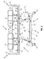
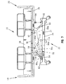
Fig. 1 is a perspective view of a hospital bed incorporating an illustrative embodiment of the obstacle detection device of the present invention; -
Fig. 2 is a side elevational view of the hospital bed ofFig. 1 , the opposite side elevational view being a mirror image thereof; -
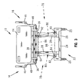
Fig. 3 is a foot end view of the hospital bed ofFig. 1 ; -
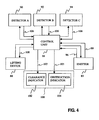
Fig. 4 is a block diagram representation of the obstacle detection device ofFig. 1 ; -
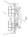
Fig. 5 is a side elevational view in partial schematic of the hospital bed ofFig. 1 , illustrating the bed in a fully raised position and with potential obstacles positioned in detection paths of the various receivers; -
Fig. 6 is a side elevational view in partial schematic similar toFig. 5 , illustrating the bed in a lowered position; -
Fig. 7 is a side elevational view in partial schematic similar toFig. 5 , illustrating the bed in an intermediate position; -
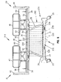
Fig. 8 is a foot end view in partial schematic of the hospital bed ofFig. 5 , illustrating the bed in a fully raised position and with potential obstacles positioned in detection paths of the various receivers; -
Fig. 9 is a flow chart illustrating the method operation associated with the obstacle detection device ofFig. 1 ; -
Fig. 10 is a perspective view of a hospital bed incorporating a further illustrative embodiment of the obstacle detection device of the present invention; -
Fig. 11 is a side elevational view of the hospital bed ofFig. 10 , the opposite side elevational view being a mirror image thereof; -
Fig. 12 is a perspective view of a hospital bed, with certain components removed for clarity, incorporating a further illustrative embodiment obstacle detection device of the present invention; -
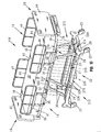
Fig. 13 is a partially exploded perspective view similar toFig. 12 , with the frame covers raised to illustrate the emitters and the detectors of the obstacle detection device; -
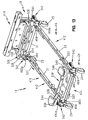
Fig. 14 is a side elevational view of the hospital bed ofFig. 12 , with the frame covers removed for clarity, the opposite side elevational view being a mirror image thereof; -
Fig. 15 is a foot end view of the hospital bed ofFig. 12 , with the frame covers removed for clarity; -
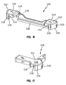
Fig. 16 is a rear perspective view of the foot end frame cover of the hospital bed ofFig. 12 ; -
Fig. 17 is a perspective view of the left side head end frame cover of the hospital bed ofFig. 12 , the right side head end frame cover being a mirror image thereof; -
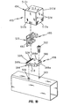
Fig. 18 is an exploded perspective view of a housing of the obstacle detection device ofFig. 12 ; -
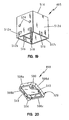
Fig. 19 is a perspective view of a cover of the housing ofFig. 18 ; -
Fig. 20 is a perspective view of a base of the housing ofFig. 18 ; -
Fig. 21 is a block diagram representation of the obstacle detection device ofFig. 12 ; -
Fig. 22 is a timing diagram of an illustrative signal generated by the emitter of the obstacle detection device ofFig. 12 ; -
Fig. 23 is an illustrative waveform generated by the detector of the obstacle detection device ofFig. 12 in response to the illustrative signal ofFig. 22 ; -
Fig 24 is an illustrative waveform as received by the microprocessor after the illustrative detector waveform ofFig. 23 passes through an RC filter; - Referring initially to
Figs. 1-3 , ahospital bed 10 is illustrated as including theobstacle detection device 12 of the present invention. Thehospital bed 10 includes opposing right and leftlongitudinal side edges head end 18 and afoot end 20. In the following description, the phrases "right side" and "left side" will be utilized to denote the relative location of an object positioned to lie nearest theright side edge 14 and leftside edge 16, respectively, of thebed 10. The phrase "head end" will be utilized to denote the relative location of an object positioned to lie nearest thehead end 18 of thehospital bed 10. Likewise, the phrase "foot end" will be used to denote the proximate location of a referenced object positioned to lie nearest thefoot end 20 of thehospital bed 10. - The
hospital bed 10 includes abase module 22 having abase frame 24 supported byconventional casters 25 which provide mobility to thebed 10. Thebase frame 24 includes aright side member 21 and aleft side member 23 connected by a footend cross member 29 and a headend cross member 31. An intermediate or elevatingframe 26 is coupled to thebase frame 24 by first and second pairs oflift arms frame 26 relative to thebase frame 24. An articulatingdeck 36 is supported for movement relative to the elevatingframe 26. Amattress 38 is carried by the articulatingdeck 36 and provides a sleeping orpatient support surface 40 configured to receive a patient. - A
headboard 42 is illustratively supported by the elevatingframe 26 proximate thehead end 18 of thebed 10 while afootboard 44 is supported by the elevatingframe 26 proximate thefoot end 20 of the bed. It should be appreciated that theheadboard 42 and thefootboard 44 may alternatively be coupled to thebase frame 24. Conventional first and second siderails 46 and 47 are provided proximate the longitudinal side edges 14 and 16 of thebed 10. Thefirst siderails 46 are positioned proximate thefoot end 20 of thebed 10, while thesecond siderails 47 are positioned proximate thehead end 18 of thebed 10. A pair ofarms deck 36 in a manner providing for relative vertical movement therebetween. - The articulating
deck 36 includes ahead section 50, aseat section 52, athigh section 54, and afoot section 56. Illustratively, thefirst siderails 46 are supported by thefoot section 56, while thesecond siderails 47 are supported by thehead section 50. As such, it should be appreciated that the siderails 46 and 47 move relative to each other as thefoot section 56 and thehead section 50 of the articulatingdeck 36 move relative to each other. Themattress 38 rests on the articulatingdeck 36 and includes ahead portion 58, aseat portion 60, athigh portion 62, and afoot portion 64, each of which generally correspond to the like-named portions of thedeck 36, and each of which is generally associated with the head, seat, thighs, and feet of a patient supported on thesurface 40. Details of the articulatingdeck 36 are of conventional design and may comprise those of the type disclosed inU.S. Patent No. 6,336,235 to Ruehl , which is assigned to the assignee of the present invention. - The
lift arms Fig. 4 ) for causing the vertical movement of the elevatingframe 26 relative to thebase frame 24. More particularly, the elevatingframe 26 is configured to move vertically between a raised position (Fig. 5 ) and a lowered position (Fig. 6 ). A plurality of intermediate positions (Fig. 7 ) are available for the elevatingframe 26 between the raised position and the lowered position. The liftingdevice 66 may comprise a conventional mechanism of the type disclosed inU.S. Patent No. 3,958,383 to Adams et al . orU.S. Patent No. 6,336,235 to Ruehl , both of which are assigned to the assignee of the present invention. - With reference now to
Figs. 1-4 , theobstacle detection device 12 of the present invention includes a first or rightside detection unit 70, associated with the right sidelongitudinal edge 14 of thehospital bed 10, a second or leftside detection unit 72 associated with the leftlongitudinal side edge 16 of thebed 10, and a third or footend detection unit 74 associated with thefoot end 20 of thebed 10. The rightside detection unit 70 is configured to generate a first optical curtain 76 (Fig. 2 ) while the leftside detection unit 72 is configured to generate a secondoptical curtain 78 substantially identical to the firstoptical curtain 76. Likewise, the footend detection unit 74 is configured to generate a third optical curtain 80 (Fig. 3 ). A fourth or head end detection unit (not shown) substantially identical to the footend detection unit 74 may likewise be provided adjacent thehead end 18 of thebed 10 for generating a fourth optical curtain (not shown) similar to theoptical curtains - Illustratively, each
detection unit emitter 82 coupled to thebase frame 24. Theemitter 82 illustratively comprises a light source, such as an infrared (IR) light emitting diode (LED). The light emitting diode may be empirically selected based upon dimensions and operating conditions of thebed 10. Illustratively, an emitting diode Model No. SFH-41SU available from OSRAM Opto Semiconductors of San Jose, California, may be utilized. However, it should be appreciated that other conventional emitters, including ultrasonic, radar, and microwave may be substituted for the infrared emitters. Abeam shaping lens 84 is positioned adjacent to eachemitter 82 for converting or shaping a beam of light emitted from theemitter 82 into the respectiveoptical curtain beam shaping lens 84 may comprise a fresnel lens of the type well-known in the art. Illustratively, Model No. H43796 available from Edmund Scientific of Tonawanda, New York, may be utilized. It should be noted that a plurality ofemitters 82 may be utilized to form each respectiveoptical curtain beam shaping lens 84. - The
emitter 82 in combination with thelens 84 directs light a predetermined distance from theemitter 82 thereby minimizing spillover to adjacent equipment. Moreover, eachrespective emitter 82 andlens 84 define a perimeter including a predetermined width and height for theoptical curtains upper edge 86 to alower edge 88 intermediate thebase frame 24 and the elevatingframe 26. Illustratively, the predetermined height is equal to the distance between thebase frame 24 and the elevatingframe 26 when the elevatingframe 26 is in its uppermost position (Fig. 5 ) as defined by the liftingdevice 66. - A plurality of
detectors emitter 82 and are configured to receive or detect the respectiveoptical curtain detectors Fig. 4 . Moreover, eachoptical curtain Figs. 5-8 ) emitting from theemitter 82 and detectable by thedetectors detectors infrared detectors emitters 82. - Referring further to
Fig. 4 , acontrol unit 98 is provided in communication with eachemitter 82 anddetector emitter 82 transmits randomly modulated wireless infrared light rays or signals 96 to form a respectiveoptical curtain verification signal 99 is then transmitted through a conventional communication link, such as hard wires (not shown) disposed within thebed base frame 24, to thecontrol unit 98. If the intensity, spectrum or modulation of the receivedwireless signal 96 at thedetector verification signal 99, thecontrol unit 98 inhibits movement of thebed 10 by the liftingdevice 66. As such, theverification signal 99 prevents external light sources, such as room lights or sunlight, from interfering with the operation of theobstacle detection device 12. - An
indicator 100 may be supported by thehospital bed 10 for providing an indication of the detection of theoptical curtain detectors indicator 100 may include a clearance indicator, illustratively in the form of agreen light 102, which is activated by aclearance signal 103 supplied by thecontrol unit 98 to provide an indication of a clear detection path between theemitter 82 and thedetectors red light 104, may be provided to indicate a failure of one of thedetectors appropriate wireless signal 96 of theoptical curtains obstruction indicator 104 is activated by anobstruction signal 105 supplied by thecontrol unit 98. It should be appreciated that theindicator 100 may comprise a single bi-color red/green status indicator. Alternatively, other indicators, such as an audible alarm or any other device which may provide an indication of the presence of an obstacle in the detection path, may be readily substituted for theobstruction indicator light 104. - With reference to
Figs. 5-9 , the operation of theobstacle detection device 12 of the present invention is described in greater detail. As illustrated inFig. 9 , the process begins atblock 202 upon activation of theobstacle detection device 12. The process continues to block 204 where therespective emitters 82 are activated. Atblock 206, theoptical curtains respective emitters 82 through the associatedbeam shaping lenses 84. - Continuing at
block 208, therespective receivers receivers respective wireless curtain curtain control unit 98. Atblock 214, theclearance indicator 102 is activated in response to theclearance signal 103 supplied by thecontrol unit 98. - If one of the
wireless curtain respective detectors block 210, then therespective detector interruption signal 106 to thecontrol unit 98. The process continues to block 216 where thecontrol unit 98 generates astop signal 108. Atblock 218, the elevatingframe lifting device 66 is deactivated in response to thestop signal 108. Atblock 220, theobstruction indicator 104 is activated in response to theobstruction signal 105 supplied by thecontrol unit 98. -
Fig. 5 illustrates thehospital bed 10 in a fully raised position. Moreover, the elevatingframe 26 is raised to its uppermost position by the liftingdevice 66 coupled to thelift arms Fig. 6 , in turn, illustrates the elevatingframe 26 of thehospital bed 10 in its lowermost position wherein the elevatingframe 26 is lowered to its position nearest thebase frame 24 through operation of thelifting device 66 and thelift arms Fig. 7 illustrates thehospital bed 10 with the elevatingframe 26 in a intermediate position between the uppermost position ofFig. 5 to the lowermost position ofFig. 6 . - It should be noted that the
lifting device 66 may be provided with position sensors (not shown) configured to provide feedback position signals to thecontrol unit 98 providing an indication of the relative vertical position of the elevatingframe 26. Such position sensors are well-known in the art and may be utilized with theobstacle detection device 12 of the present invention to prevent the elevatingframe 26 from moving outside of the range of theoptical curtains - As noted above, the
receivers optical curtain wireless signals 96 making up or forming therespective curtains emitter 82 to thereceivers Representative wireless signals Figs. 5 and8 . Potential obstacles are represented byreference numerals Fig. 5 and are placed within the respective detection paths ofsignals obstacles wireless signals optical curtains respective detectors obstacles -
Figs. 10 and11 illustrate ahospital bed 310 including an alternative embodimentobstacle detection device 312 of the present invention. Theobstacle detection device 312 includes a first or rightside detection unit 370 associated with the rightlongitudinal side edge 14 of thehospital bed 310, a second or leftside detection unit 372 associated with the leftlongitudinal side edge 16 of thebed 310, and a third or footend detection unit 374 associated with thefoot end 20 of thebed 310. The rightside detection unit 370 is configured to generate a firstoptical curtain 376, while the leftside detection unit 372 is configured to generate a secondoptical curtain 378. Likewise, the footend detection unit 374 is configured to generate a thirdoptical curtain 380. A fourth or head end detection unit (not shown) may be provided adjacent thehead end 18 of thebed 310 for generating a fourth optical curtain (not shown) similar to theoptical curtains - Illustratively, each
detection unit obstacle detection device 312 includes a first orlower support 326 including a plurality of spaced apartemitters 328. Eachemitter 328 preferably comprises a self-contained infrared light-emitting diode. The emitters produce a beam oflight 330 upwardly toward the elevating frame of thebed 10. As illustrated inFigs. 10 and11 , each beam oflight 330 is discrete and spaced apart from adjacent beams oflight 330. Collectively, the plurality of beams oflight 330 define the respectiveoptical curtains - Each
detection unit optical detection device 312 further includes a second orupper support 332 including a plurality ofdetectors 334. Eachdetector 334 is associated with one of theemitters 328 and is configured to receive or detect therespective light beam 330 defining theoptical curtains - In a manner similar to that detailed above, if an obstacle is located in the
optical curtain emitters 328 anddetectors 334, such that one of the light beams 330 is interrupted, then thecontrol unit 98 prevents thelifting device 66 from vertically moving the elevatingframe 26. - It should be noted that the
optical curtains obstacle detection device 312 require that thelight beams 330 be accurately aligned between theemitters 328 and thedetectors 334 throughout the full path of travel of the elevatingframe 26. It may be appreciated, non-linear movement of the elevatingframe 26 relative to thebase frame 24 may cause therespective emitters 328 anddetectors 334 to become mis-aligned, thereby resulting in a signal to thecontrol unit 98 that an obstacle is positioned within theoptical curtain optical curtains - The
individual detection units obstacle detection device 312 may comprise the EASY-GUARD™ grid system available from Banner Engineering Corp. of Minneapolis, Minnesota. However, it should be appreciated that other similar devices may be substituted therefor. -
Figs. 12 and13 , illustrate portions of ahospital bed 410 including a further illustrative embodimentobstacle detection device 412 of the present invention. Theobstacle detection device 412 includes a first or rightside detection unit 470 associated with the rightlongitudinal side edge 14 of thehospital bed 410, a second or leftside detection unit 472 associated with the leftlongitudinal side edge 16 of thebed 310, and a third or footend detection unit 474 associated with thefoot end 20 of thebed 310. The rightside detection unit 470 is configured to detect an obstacle proximate the top of theright side member 21 of thebase frame 24, while the leftside detection unit 472 is configured to detect an obstacle along the top of theleft side 23 of thebase frame 24. Likewise, the footend detection unit 474 is configured to detect an obstacle in front of the footend cross member 29 of thebase frame 24 at thefoot end 20 of thebed 410. It should be appreciated that a fourth or head end detection unit (not shown) may be provided adjacent thehead end 18 of thebed 410 for detecting an obstacle behind the headend cross member 31 of thebase frame 24 of thebed 410. - As shown in
Figs. 13-15 and21 , eachdetection unit obstacle detection device 412 includes anemitter detector emitter microprocessor 485 which generates an infrared (IR) signal that is configured to be received by the associateddetector 490. Themicroprocessor 485 illustratively comprises a conventional eight-bit microprocessor and may comprise Part No. MC68HC908QT1CDW available from Motorola of Schaumburg, Illinois. A voltage regulator 487 is used to interface themicroprocessor 485 to an 8.2 volt input provided by thepower source 488 of apower supply module 489. The output of themicroprocessor 485 interfaces with theLED 483, which converts the electrical signal into an optical one. - The
detector 490 includes an IR sensor 491 which is configured to receive the optical signal emitted from the emitter 482 and convert the optical signal to an electrical signal. Illustratively, the sensor 491 is an infrared photo diode configured to observe a specific signal frequency and may comprise infrared detector Part No. GP1UM267XK available from Sharp Microelectronics of Camas, Washington. The IR sensor 491 is interfaced to the 8.2volt power source 488 via a conventional regulator 492. The output of thedetector 490 is routed through a buffer 493 and to thepower supply module 489 for processing in the manner described herein. - While the illustrative emitters 482 and
detectors 490 utilize infrared light, it should be appreciated that other wireless signals may be substituted therefore. More particularly, other forms of electromagnetic radiation, such as ultrasonic, radar, and microwave, may be substituted for IR light. - With reference to
Figs. 12 ,13 , and16-20 , each emitter 482 anddetector 490 is received within ahousing 494. Eachhousing 494 includes acover 495 coupled to abase 498. Thebase 498 includes a mountingaperture 500 configured to receive afastener 502 for securing the base 498 to anaperture 503 formed in thebase frame 24 of thebed 410. A locatingpeg 504 extends downwardly from a lower surface of thebase 498 and is configured to be received within anaperture 506 formed in thebase frame 24 of thebed 410. As such, the combination of thefastener 502 received within theaperture 503 and the locatingpeg 504 received within theaperture 506 provides for the proper orientation and coupling of thehousing 494 relative to thebase frame 24. The base 498 further includes fourside walls 508 having a pair of notches orslots 510 formed in a pair of opposing ones of theside walls - The cover 496 includes four side walls 512 and a
top wall 514. A pair of lockingtabs 516 are resiliently supported by an opposing pair of theside walls notches 510 of thebase 498. Cooperatingslots base 498 and are configured to receive components, as supported on acircuit board 522, of the respective emitter 482 anddetector 490. A pair ofapertures 524 are formed within one of theside walls 512a of the cover 496 and are aligned with theLED 483 of the emitter 482 or the sensor 491 of thedetector 490. Theapertures 524 are positioned and sized for the efficient transmission of infrared light without incurring substantial interference from external light sources. Illustratively, theapertures 524 have a diameter of 3.18 millimeters (.125 inches) and are positioned approximately 24.2 mm (.953 inches) in front of the mountingslots respective circuit board 522. - With reference to
Figs. 12 ,13 ,16, and 17 , the respective housings 440 are protected from fluid ingress by caster or frame covers 526, 528, 530 that cover portions of thebase frame 24 proximate the head and foot ends 18 and 20. Each headend frame cover housing 531 havingside walls 532 connected to atop wall 534. One of theside walls 532 includes anopening 536 aligned with one of theapertures 524 in one of thehousings 494 associated with the right and leftside detection units transparent window 538, illustratively a clear thermoplastic material, is fixed within theopening 536 to prevent the passage of fluid therethrough, while permitting the passage of infrared light from the emitter 482 to thedetector 490. Thewindow 538 may be fixed in place using conventional methods, such as ultrasonic welding or adhesives. Aclearance slot 540 may be formed in another one of theside walls 532 of the frame covers 526 and 528 to provide clearance for the brake/steer pedals 542 of thehospital bed 410, as needed. - The foot
end frame cover 530 includes first andsecond housings member 548. Eachhousing side walls 550 coupled to atop wall 552, and a pair ofopenings side walls 550. Theopenings 554 are associated with one of theapertures 524 of thefoot end housings 494 of the right and leftside detection units openings 556 are associated with one of theapertures 524 of thehousings 494 associated with the footend detection unit 474.Windows 538 are illustratively fixed within theopenings - As illustrated in
Figs. 12 and13 , the right and leftside detection units head end 18 andfoot end 20 of thehospital bed 410, respectively. As such, the transmission of infrared light from the emitters 482 of the rightside detection unit 470 and the leftside detection unit 472 will be in opposite directions (as shown byarrows 557 inFig. 13 ) in order to reduce the possibility of cross talk between the twodetection units end detection unit 474 does not direct infrared light toward thedetectors 490 of the right and leftside detection units - To begin operation of the
obstacle detection device 412, a controller ormicroprocessor 558 of thepower supply module 489 initializes the various parameters and disables all interrupts. Thepower source 488 of thepower supply module 489 supplies each emitter 482 with the required power of 8.2 volts. Themicroprocessor 485 of each emitter 482 is used to cause theLED 483 to generate anIR pulse signal 560 of the type illustrated inFig. 22 . Illustratively, thesignal 560 includes a 600 microsecond pulsedportion 561 having a 57 kHz signal with a 50 percent duty cycle. A two millisecond delay follows the 57 kHz pulse with the output low. Such a pulse sequence repeats indefinitely. An internal bus clock (not shown) illustratively runs at 3.2 MHz. As such, this provides an instruction cycle time of 312.5 nanoseconds. - The
detector 490 is configured to look for a 56.8 kHz signal, which translates into 17.66 microseconds per pulse, or 8.803 microseconds per state. The number of instruction cycles per state is determined by the following formula:
- By inserting the above values for total time of 8.803 microseconds and instruction cycle time of 312.5 nanoseconds, the number of instruction cycles is determined to be 28.17. Using 28 cycles per state provides a total pulse time of 17.5 microseconds which equates to 57.14 kHz. A loop that generates the 57 kHz IR signal is run 34 times, thereby giving a total time of 595 microseconds.
- The
detector 490 is configured to look for thepulse signal 560 including a pulsed portion or an IR signal burst 561 at a specific frequency. When thesignal 560 is detected with the appropriate frequency component, the output of thedetector 490 becomes active, effectively demodulating the transmitted signal. Thedetector 490 includes a built-in frequency filter having a range of 53.6 kHz to 60 kHz (56.8 ± 3.2 kHz). - In addition to a band-pass filter, the
IR detector 490 adjusts its sensitivity level proportionately to the strength of the incident light signal. This helps further filter noise signals that may be present in the 56.8 kHz range. - The
IR detector 490 filters the incident light to allow only the wave length associated with IR to come into contact with the internal photo diode or sensor 491. This helps filter out the effects of sunlight, incandescent lighting, and fluorescent lights. - Upon detecting the appropriate wave length or
frequency pulse signal 560, thedetector 490 provides an essentially demodulated signal 562 such as that illustrated inFig. 23 . The signal illustratively has a high value of approximately 5 volts. - The
demodulated signal 562 from thedetector 490 is then transmitted to a Resistor-Capacitor (RC)filter 564 comprising part of thepower supply module 489. TheRC filter 564 converts thesignal 562 ofFig. 23 to awaveform 566 such as that illustrated inFig. 24 . The waveform ofFig. 24 has a nominal value of approximately 3.8 volts ± 0.5 volts. Illustratively, theRC filter 564 is of conventional design and includes a 100 kohm resistor and a 0.1 µF capacitor. The output from theRC filter 564 passes through a conventional analog to digital (A/D) converter (not shown) on its way to themicroprocessor 558. - If the RC filter output drops below 3.3 volts, then the microprocessor knows that an obstacle has blocked the IR light path between the emitter 482 and the
detector 490, or that a fault condition exists, such as the emitter 482 ordetector 490 not functioning properly. In either case, themicroprocessor 558 functions by activating anindicator 100 and disabling thelifting device 66 from further lowering of the patient support as detailed herein. - It should be appreciated that each emitter 482 and
detector 490 could be configured to send and receive signal waveforms having different bit or pulse patterns, including different pulse frequencies and pulse durations, in order to further limit the possibility of cross talk between different emitters and detectors. As may be appreciated, since thedetectors 490 are configured to detect a frequency rather than an intensity, interference from external light sources is reduced. Furthermore, by looking for frequency, similar emitters 482 anddetectors 490 may be used for obstacle detection for a wide range of distances between the respective emitters 482 anddetectors 490.
Claims (16)
- A hospital bed obstacle detection device (12, 312, 412) for use with a hospital bed (10, 310, 410) including a base frame (24) and an elevating frame (26) coupled to a patient support surface (40), said obstacle detection device controlling movement of the elevating frame (26) relative to the base frame (24) upon detecting an object within a path of travel of the elevating frame (26), said obstacle detection device comprising detection means (90, 92, 94, 334, 490a, 490b, 490c) for generating an output signal in response thereto, and means (98) for receiving said signal and controlling movement of the elevating frame (26) in response thereto, characterised in that said obstacle detection device (12, 312, 412) comprises means (82, 328, 482a, 482b, 482c) for generating a wireless curtain (76, 78, 80, 376, 378, 380) within a path of travel of the elevating frame (26), the detection means detecting said wireless curtain (76, 78, 80, 376, 378, 380).
- The device of claim 1, wherein the generating means comprises an optical curtain generator (82, 328, 482a, 482b, 482c), the detecting means comprises an optical curtain detector (90, 92, 94, 334, 490a, 490b, 490c) and the control means comprises a control unit in communication with said detector (90, 92, 94, 334, 490a, 490b, 490c), said control unit (98) being configured to prevent relative movement of said base frame (24) and elevating frame (26) upon failure of said detector (90, 92, 94, 334, 490a, 490b, 490c) to detect said optical curtain (76, 78, 80, 376, 378, 380).
- The obstacle detection device of claim 1 wherein the generating means comprises an emitter (82, 328, 482a, 482b, 482c) coupled to one of the base frame (24) and the elevating frame (26) of the bed (10, 310, 410), the emitter (82, 328, 482a, 482b, 482c) being configured to generate a wireless curtain (76, 78, 80, 376, 378, 380) extending below the elevating frame, the detecting means comprises a receiver (90, 92, 94, 334, 490a, 490b, 490c) coupled to one of the base frame (24) and the elevating frame (26) of the bed (10, 310, 410), and the control means comprises a control unit (98) in communication with said receiver (90, 92, 94, 334, 490a, 490b, 490c).
- The obstacle detection device of claim 3, wherein said emitter comprises an infrared light source (82, 328, 482a, 482b, 482c), and said wireless curtain comprises an optical curtain.
- The obstacle detection device of claim 4, further comprising a lens (84) positioned proximate said infrared light source (82) and configured to convert light emitted from said infrared light source to said optical curtain.
- The obstacle detection device of claim 5, wherein said lens comprises a fresnel lens (84).
- The obstacle detection device of any one of claims 3 to 6, wherein said wireless curtain includes a modulated signal and said receiver (490) compares said modulated signal to a predefined verification signal to prevent interference from external light sources.
- The obstacle detection device of any one of claims 3 to 7, wherein said receiver (90, 92, 94, 334, 490a, 490b, 490c) is configured to move with said elevating frame (26) within a predefined vertical range.
- The obstacle detection device of claim 8, wherein said predefined vertical range is from said base frame (24) to said elevating frame (26) when said elevating frame (26) is in a fully raised position.
- The obstacle detection device of any one of claims 3 to 9, further comprising an indicator (100) in communication with the control unit (98), said indicator (100) configured to indicate failure of said receiver (90, 92, 94, 334, 490a, 490b, 490c) to detect said wireless curtain (76, 78, 80, 376, 378, 380).
- The obstacle detection device of claim 10, wherein said indicator (100) comprises a light.
- The obstacle detection device of claim 10, wherein said indicator (100) comprises an audible alarm.
- The obstacle detection device of any one of claims 3 to 12, wherein said control unit comprises a processor (558) in communication with an actuator (66) configured to move the elevating frame (26) relative to the base frame (24).
- The obstacle detection device of any one of claims 3 to 12, wherein said control unit comprises a control relay coupled to an actuator (66) configured to move the elevating frame (26) relative to the base frame (24).
- The obstacle detection device of any one of claims 3 to 14, wherein the emitter (328) generates a plurality of wireless signals in a plurality of signal paths, a plurality of receivers (334) are configured to detect said wireless signals along different ones of said signal paths, and said control unit (98) prevents movement of the elevating frame (26) relative to the base frame (24) when any of said receivers fail to detect a wireless signal.
- The obstacle detection device of any one of claims 3 to 15, wherein said receiver (90, 92, 94, 334, 490a, 490b, 490c) generates said output signal when said receiver (90, 92, 94, 334, 490a, 490b, 490c) does not detect said wireless curtain (76, 78, 80, 376, 378, 380).
Priority Applications (2)
| Application Number | Priority Date | Filing Date | Title |
|---|---|---|---|
| EP20090002423 EP2055286B1 (en) | 2002-04-19 | 2003-04-21 | Hospital bed obstacle detection device |
| EP20100011366 EP2319473A3 (en) | 2002-04-19 | 2003-04-21 | Hospital bed obstacle detection device and method |
Applications Claiming Priority (5)
| Application Number | Priority Date | Filing Date | Title |
|---|---|---|---|
| US37381902P | 2002-04-19 | 2002-04-19 | |
| US373819P | 2002-04-19 | ||
| US40869802P | 2002-09-06 | 2002-09-06 | |
| US408698P | 2002-09-06 | ||
| PCT/US2003/012166 WO2003088885A1 (en) | 2002-04-19 | 2003-04-21 | Hospital bed obstacle detection device and method |
Related Child Applications (2)
| Application Number | Title | Priority Date | Filing Date |
|---|---|---|---|
| EP20100011366 Division EP2319473A3 (en) | 2002-04-19 | 2003-04-21 | Hospital bed obstacle detection device and method |
| EP20090002423 Division EP2055286B1 (en) | 2002-04-19 | 2003-04-21 | Hospital bed obstacle detection device |
Publications (2)
| Publication Number | Publication Date |
|---|---|
| EP1496830A1 EP1496830A1 (en) | 2005-01-19 |
| EP1496830B1 true EP1496830B1 (en) | 2009-03-11 |
Family
ID=29254537
Family Applications (3)
| Application Number | Title | Priority Date | Filing Date |
|---|---|---|---|
| EP20090002423 Expired - Fee Related EP2055286B1 (en) | 2002-04-19 | 2003-04-21 | Hospital bed obstacle detection device |
| EP03721786A Expired - Lifetime EP1496830B1 (en) | 2002-04-19 | 2003-04-21 | Hospital bed obstacle detection device |
| EP20100011366 Withdrawn EP2319473A3 (en) | 2002-04-19 | 2003-04-21 | Hospital bed obstacle detection device and method |
Family Applications Before (1)
| Application Number | Title | Priority Date | Filing Date |
|---|---|---|---|
| EP20090002423 Expired - Fee Related EP2055286B1 (en) | 2002-04-19 | 2003-04-21 | Hospital bed obstacle detection device |
Family Applications After (1)
| Application Number | Title | Priority Date | Filing Date |
|---|---|---|---|
| EP20100011366 Withdrawn EP2319473A3 (en) | 2002-04-19 | 2003-04-21 | Hospital bed obstacle detection device and method |
Country Status (7)
| Country | Link |
|---|---|
| US (6) | US7472437B2 (en) |
| EP (3) | EP2055286B1 (en) |
| AT (1) | ATE424798T1 (en) |
| AU (1) | AU2003225079A1 (en) |
| CA (1) | CA2482462A1 (en) |
| DE (1) | DE60326558D1 (en) |
| WO (1) | WO2003088885A1 (en) |
Cited By (1)
| Publication number | Priority date | Publication date | Assignee | Title |
|---|---|---|---|---|
| CN110946722A (en) * | 2018-09-27 | 2020-04-03 | 希尔-罗姆服务公司 | Infrared beam filter for obstacle detection |
Families Citing this family (56)
| Publication number | Priority date | Publication date | Assignee | Title |
|---|---|---|---|---|
| US6611979B2 (en) | 1997-09-23 | 2003-09-02 | Hill-Rom Services, Inc. | Mattress having a retractable foot section |
| AU2003225079A1 (en) | 2002-04-19 | 2003-11-03 | Hill-Rom Services, Inc. | Hospital bed obstacle detection device and method |
| AU2003274957B2 (en) | 2002-09-06 | 2009-07-16 | Hill-Rom Services, Inc. | Hospital bed |
| DE20319312U1 (en) | 2003-12-12 | 2005-05-04 | Dewert Antriebs- Und Systemtechnik Gmbh & Co. Kg | Furniture |
| US7411174B2 (en) * | 2004-10-12 | 2008-08-12 | Eash Brandon A | Sensor-controlled LED array apparatus and method |
| GB0506691D0 (en) * | 2005-04-01 | 2005-05-11 | Pegasus Ltd | Height-adjustable bed |
| DE102005015795B4 (en) | 2005-04-06 | 2008-02-14 | Siemens Ag | Device protection for lifting unit |
| EP1896872B1 (en) * | 2005-06-08 | 2016-10-19 | C-Dax Limited | Improvements in or relating to pasture management |
| EP1906794A4 (en) * | 2005-07-08 | 2014-05-07 | Hill Rom Services Inc | Control unit for patient support |
| EP2260755B1 (en) | 2005-11-07 | 2013-12-25 | Stryker Corporation | Patient handling device including normal condition lamp |
| DE602006014295D1 (en) * | 2005-11-09 | 2010-06-24 | Hill Rom Services Inc | AIR VALVE ASSEMBLY FOR A PATIENT SUPPORT |
| CN101431974B (en) * | 2006-04-27 | 2012-07-04 | 利纳克有限公司 | Bed, preferably hospital or care bed |
| DE102007018694B4 (en) | 2007-04-18 | 2009-04-09 | Dr. Ing. H.C. F. Porsche Aktiengesellschaft | Bed and a method for controlling or safety device for a bed |
| DE102007018693A1 (en) | 2007-04-18 | 2008-10-23 | Dr. Ing. H.C. F. Porsche Aktiengesellschaft | Stroke movement device for care bed, has receiver light conductor receiving light field, which extends parallel to contour of lower surface of platform, where field is upstream to platform and is viewed in direction of motion of platform |
| US8039766B2 (en) * | 2009-09-15 | 2011-10-18 | Hill-Rom Services, Inc. | Obstruction detecting force sensing system wherein the threshold force value for detecting an obstruction is set according to the configuration of the bed |
| US8442738B2 (en) * | 2009-10-12 | 2013-05-14 | Stryker Corporation | Speed control for patient handling device |
| EP2338456A1 (en) * | 2009-12-22 | 2011-06-29 | Invacare International Sàrl | Method for securitizing the lifting operation of a wheelchair seat and Lifting Device fo a wheelchair |
| US8350709B2 (en) * | 2010-03-31 | 2013-01-08 | Hill-Rom Services, Inc. | Presence detector and occupant support employing the same |
| US8266741B2 (en) | 2010-08-10 | 2012-09-18 | Hill-Rom Services, Inc. | Bed movement cessation based on IV pump alarm |
| EP2619724A2 (en) * | 2010-09-23 | 2013-07-31 | Stryker Corporation | Video monitoring system |
| US8959681B2 (en) * | 2010-12-20 | 2015-02-24 | Hill-Rom Services, Inc. | Ground sensor control of foot section retraction |
| EP3459516B1 (en) | 2011-11-22 | 2021-03-10 | Paramount Bed Co., Ltd. | Bed device |
| EP2790631B1 (en) * | 2011-12-16 | 2017-02-01 | Stryker Corporation | Patient support overload or obstruction detection |
| KR101366543B1 (en) * | 2012-01-26 | 2014-02-26 | 삼성메디슨 주식회사 | Castor indicator |
| WO2013123119A1 (en) | 2012-02-15 | 2013-08-22 | Stryker Corporation | Patient support apparatus and controls therefor |
| US10123923B2 (en) * | 2012-02-21 | 2018-11-13 | Sizewise Rentals, L.L.C. | Auto leveling low profile patient support apparatus |
| US9228885B2 (en) | 2012-06-21 | 2016-01-05 | Hill-Rom Services, Inc. | Patient support systems and methods of use |
| US9259369B2 (en) * | 2012-09-18 | 2016-02-16 | Stryker Corporation | Powered patient support apparatus |
| WO2014201379A2 (en) * | 2013-06-15 | 2014-12-18 | Hill-Rom Services, Inc. | Adjustable person support system |
| US10188569B2 (en) | 2013-09-06 | 2019-01-29 | Stryker Corporation | Patient support usable with bariatric patients |
| CA2923210C (en) | 2013-09-06 | 2022-07-12 | Stryker Corporation | Patient support usable with bariatric patients |
| EP2873400B1 (en) | 2013-11-18 | 2018-01-31 | Völker GmbH | Person support apparatus |
| US9603764B2 (en) | 2014-02-11 | 2017-03-28 | Medline Industries, Inc. | Method and apparatus for a locking caster |
| WO2015138317A1 (en) | 2014-03-10 | 2015-09-17 | Stryker Corporation | Limb positioning system |
| US10426679B2 (en) | 2014-08-27 | 2019-10-01 | Umano Medical Inc. | Systems for patient support surface orientation and displacement |
| EP3206654B1 (en) * | 2014-10-17 | 2020-11-25 | Stryker Corporation | Person support apparatuses with motion monitoring |
| US9951904B2 (en) | 2015-03-24 | 2018-04-24 | Stryker Corporation | Rotatable seat clamps for rail clamp |
| US10517784B2 (en) | 2015-05-29 | 2019-12-31 | Hill-Rom Services, Inc. | Patient support apparatus |
| US11020297B2 (en) | 2015-12-22 | 2021-06-01 | Stryker Corporation | Powered side rail for a patient support apparatus |
| US10736803B2 (en) | 2016-02-26 | 2020-08-11 | Stryker Corporation | Lift assembly for patient support apparatus |
| US10842701B2 (en) | 2016-10-14 | 2020-11-24 | Stryker Corporation | Patient support apparatus with stabilization |
| EP3518854A4 (en) * | 2016-11-28 | 2020-09-02 | Verb Surgical Inc. | Robotic surgical system to reduce unwanted vibration |
| US10499997B2 (en) | 2017-01-03 | 2019-12-10 | Mako Surgical Corp. | Systems and methods for surgical navigation |
| CN106901909B (en) * | 2017-03-20 | 2018-04-10 | 韩先章 | A kind of medical sickbed |
| US10987268B2 (en) | 2017-04-21 | 2021-04-27 | Stryker Corporation | Emergency cot with a litter height adjustment mechanism |
| US10987260B2 (en) | 2017-04-21 | 2021-04-27 | Stryker Corporation | Patient handling apparatus with hydraulic control system |
| US11090209B2 (en) | 2017-06-20 | 2021-08-17 | Stryker Corporation | Patient support apparatus with control system and method to avoid obstacles during reconfiguration |
| US11213443B2 (en) | 2017-12-29 | 2022-01-04 | Stryker Corporation | Indication system to identify open space beneath patient support apparatus |
| USD909805S1 (en) * | 2018-02-15 | 2021-02-09 | Michael F. Kunde | Transfer bar |
| US11344228B2 (en) * | 2018-05-02 | 2022-05-31 | Wernher Ovalle | Patient monitoring device and system |
| US20190380896A1 (en) * | 2018-06-15 | 2019-12-19 | Andy Wang | Chair safety system against accidental pressing |
| EP3610840A1 (en) | 2018-08-14 | 2020-02-19 | Gymna Uniphy | Treatment couch with safety improvement |
| CN109875781B (en) * | 2019-04-23 | 2020-09-11 | 绍兴第二医院医共体总院(绍兴第二医院) | Medical multifunctional sickbed |
| US11896531B2 (en) | 2019-10-28 | 2024-02-13 | Stryker Corporation | Hydraulic circuit for a patient handling apparatus |
| US11583455B2 (en) | 2019-10-28 | 2023-02-21 | Stryker Corporation | Hydraulic valve and system |
| US11730650B2 (en) | 2019-12-30 | 2023-08-22 | Stryker Corporation | Patient support apparatus with hydraulic oscillation dampening |
Family Cites Families (65)
| Publication number | Priority date | Publication date | Assignee | Title |
|---|---|---|---|---|
| US1078077A (en) | 1913-06-23 | 1913-11-11 | Nat Spring Bed Company | Bed. |
| US2527111A (en) | 1947-10-07 | 1950-10-24 | Walter Brumbach | Vertically adjustable bed construction |
| US2900521A (en) * | 1953-07-21 | 1959-08-18 | Westinghouse Electric Corp | Door control apparatus |
| DE2007840C3 (en) | 1970-02-20 | 1979-11-15 | Endl, Alfons, 8000 Muenchen | Light barrier |
| US3704396A (en) | 1971-05-12 | 1972-11-28 | Cincinnati Inc | Safety device for machines |
| US3951861A (en) * | 1971-06-14 | 1976-04-20 | Sumitomo Chemical Company, Limited | Catalysts for the preparation of acrolein |
| US3746863A (en) * | 1972-03-15 | 1973-07-17 | Exotron Ind Ltd | Light curtain control for a switch |
| DE2247053C3 (en) * | 1972-09-26 | 1979-08-09 | Erwin Sick Gmbh Optik-Elektronik, 7808 Waldkirch | Light barrier |
| US4023887A (en) * | 1972-10-30 | 1977-05-17 | General Optimation, Inc. | Optical communication, switching and control apparatus and systems and modular electro-optical logic circuits, and applications thereof |
| SE372085B (en) * | 1973-02-27 | 1974-12-09 | L Svensson | |
| US3805061A (en) * | 1973-04-23 | 1974-04-16 | Tyco Laboratories Inc | Object detecting apparatus |
| US3970846A (en) * | 1973-10-29 | 1976-07-20 | Xenex Corporation | Presence detecting system with self-checking |
| US3958283A (en) | 1974-08-09 | 1976-05-25 | Hill-Rom Company, Inc. | Elevating and Trendelenburg mechanism for an adjustable bed |
| US3958383A (en) | 1975-03-19 | 1976-05-25 | The Standard Products Company | Glazing system |
| US4266124A (en) * | 1979-08-10 | 1981-05-05 | Data Instruments, Inc. | Photoelectric object detector system |
| US4520262A (en) * | 1979-09-10 | 1985-05-28 | Kenneth Ambler | Photoelectric safety screen with stray source detection |
| DE2939833C2 (en) * | 1979-10-01 | 1982-06-09 | Universal-Maschinenfabrik Dr. Rudolf Schieber Gmbh & Co Kg, 7081 Westhausen | Protective device for the movement space of the slide of a flat knitting machine |
| US4463463A (en) * | 1980-03-28 | 1984-08-07 | Aisin Seiki Kabushiki Kaisha | Adjustable bed |
| US4403214A (en) * | 1980-10-27 | 1983-09-06 | William Wolar | Protective device for attachments affixed to electrically operated beds |
| US4325061A (en) * | 1980-10-27 | 1982-04-13 | William Wolar | Protective means for attachments affixed to electrically operated beds |
| US4794248A (en) * | 1985-07-16 | 1988-12-27 | Otis Elevator Company | Detection device having energy transmitters located at vertically spaced apart points along movable doors |
| USRE33668E (en) * | 1981-02-10 | 1991-08-20 | Otis Elevator Company | Detection device having energy transmitters located at vertically spaced apart points along movable doors |
| DE3313843C2 (en) | 1983-04-16 | 1986-01-16 | Volkmar 5600 Wuppertal Hahn | Sickbed |
| US4552403A (en) * | 1983-09-29 | 1985-11-12 | Hamilton Industries | Power-operated medical examination table |
| US4534077A (en) * | 1983-10-03 | 1985-08-13 | Simmons Universal Corporation | Hospital bed having safety mechanism |
| US4645920A (en) * | 1984-10-31 | 1987-02-24 | Carroll Touch, Inc. | Early fault detection in an opto-matrix touch input device |
| US4724554A (en) * | 1986-09-12 | 1988-02-16 | Standex International | Tilting patient treatment table having safety switch mat mechanism |
| JPH07119Y2 (en) * | 1988-03-18 | 1995-01-11 | 三和シヤッター工業株式会社 | Electric lifting bed |
| GB2199803B (en) * | 1987-01-20 | 1991-05-29 | Sanwa Shutter Corp | Elevation bed |
| DE3716917C2 (en) | 1987-05-20 | 1996-07-18 | Franke Gmbh & Co Kg | Installation fitting for a bed frame |
| DE3734902C1 (en) | 1987-10-15 | 1989-04-13 | Stollenwerk Fabrik Fuer Sanita | Carriage for a stretcher |
| US4882566A (en) * | 1988-08-03 | 1989-11-21 | Hill-Rom Company, Inc. | Safety control system for a hospital bed |
| US4960271A (en) * | 1988-08-08 | 1990-10-02 | John K. Grady | Medical patient support table |
| US5156166A (en) * | 1988-08-08 | 1992-10-20 | John K. Grady | Medical patient support table |
| JPH02156950A (en) | 1988-12-09 | 1990-06-15 | Paramaunto Bed Kk | Raising/lowering and tilting mechanism for floor part supporting frame |
| US5181288A (en) * | 1989-05-30 | 1993-01-26 | The Mediscus Group Inc. | Therapeutic turning bed |
| JPH0681998A (en) * | 1992-07-15 | 1994-03-22 | Nippon Signal Co Ltd:The | Fail safe scanning circuit and multi-optical axis beam type sensor |
| US5280622A (en) * | 1992-07-17 | 1994-01-18 | Mitsubishi Semiconductor America, Inc. | Combined light beam and ultrasonic transducer safety sensing system |
| US5317769A (en) * | 1992-11-10 | 1994-06-07 | Hill-Rom Company, Inc. | Hospital bed |
| US5715548A (en) | 1994-01-25 | 1998-02-10 | Hill-Rom, Inc. | Chair bed |
| US5468216A (en) * | 1994-10-12 | 1995-11-21 | Physicians Consulting Incorporated | Kinetic rehabilitation device employing controlled passive motion |
| CA2158902A1 (en) * | 1994-10-25 | 1996-04-26 | Brian J. Amend | Weak beam detection |
| US5567931A (en) * | 1994-10-25 | 1996-10-22 | Otis Elevator Company | Variable beam detection using a dynamic detection threshold |
| ATE200613T1 (en) * | 1995-03-08 | 2001-05-15 | Alliance Invest Ltd | THERAPEUTIC BED |
| US5758371A (en) * | 1995-05-18 | 1998-06-02 | Vandyke; John Paul | Self-propelled independent mechanical handling device |
| IES80505B2 (en) | 1995-12-06 | 1998-08-12 | Simon Betson | A bed |
| US6351861B1 (en) | 1998-05-29 | 2002-03-05 | Hill-Rom Services, Inc. | Bed frame |
| US5984404A (en) * | 1997-02-25 | 1999-11-16 | Freightliner Corporation | Vehicle with bed raising and lowering system |
| US6611979B2 (en) * | 1997-09-23 | 2003-09-02 | Hill-Rom Services, Inc. | Mattress having a retractable foot section |
| FR2770396B1 (en) * | 1997-11-06 | 2000-03-10 | Sunrise Medical Sa | BED COMPRISING A HEIGHT-ADJUSTABLE FRAME AND A DESCENT SAFETY DEVICE OF SAID FRAME |
| JP2879820B1 (en) | 1998-04-20 | 1999-04-05 | パラマウントベッド株式会社 | Motorized bed having an extension / reverse extension mechanism with bottom horizontal detection means |
| US6199508B1 (en) | 1998-06-22 | 2001-03-13 | Theresa Miale | Animal lift and transport apparatus |
| GB2343371B (en) * | 1998-11-03 | 2000-09-27 | Ulland Islwyn Watkins | Control of powered furniture |
| US7834768B2 (en) * | 1999-03-05 | 2010-11-16 | Hill-Rom Services, Inc. | Obstruction detection apparatus for a bed |
| US6208250B1 (en) * | 1999-03-05 | 2001-03-27 | Hill-Rom, Inc. | Patient position detection apparatus for a bed |
| US6791460B2 (en) * | 1999-03-05 | 2004-09-14 | Hill-Rom Services, Inc. | Patient position detection apparatus for a bed |
| US6161891A (en) * | 1999-10-21 | 2000-12-19 | Cts Corporation | Vehicle seat weight sensor |
| WO2001062151A1 (en) | 2000-02-23 | 2001-08-30 | Hill-Rom Services, Inc. | Bed latch position detector and method |
| US6167991B1 (en) * | 2000-02-28 | 2001-01-02 | Otis Elevator Company | Method and apparatus for detecting position of an elevator door |
| US6354716B1 (en) * | 2000-08-04 | 2002-03-12 | Honeywell International Inc | Light curtain device |
| FR2819173B1 (en) * | 2001-01-09 | 2003-04-11 | Alm | MULTI-SECTIONS MOTORIZED OPERATING TABLE |
| US6671905B2 (en) * | 2001-03-29 | 2004-01-06 | Kci Licensing, Inc. | Prone positioning therapeutic bed |
| AU2003225079A1 (en) | 2002-04-19 | 2003-11-03 | Hill-Rom Services, Inc. | Hospital bed obstacle detection device and method |
| AU2003274957B2 (en) * | 2002-09-06 | 2009-07-16 | Hill-Rom Services, Inc. | Hospital bed |
| US6983499B2 (en) * | 2003-05-21 | 2006-01-10 | Dreamwell, Ltd. | Adjustable bed shields |
-
2003
- 2003-04-21 AU AU2003225079A patent/AU2003225079A1/en not_active Abandoned
- 2003-04-21 EP EP20090002423 patent/EP2055286B1/en not_active Expired - Fee Related
- 2003-04-21 DE DE60326558T patent/DE60326558D1/en not_active Expired - Lifetime
- 2003-04-21 AT AT03721786T patent/ATE424798T1/en not_active IP Right Cessation
- 2003-04-21 US US10/510,996 patent/US7472437B2/en not_active Expired - Lifetime
- 2003-04-21 WO PCT/US2003/012166 patent/WO2003088885A1/en not_active Application Discontinuation
- 2003-04-21 EP EP03721786A patent/EP1496830B1/en not_active Expired - Lifetime
- 2003-04-21 EP EP20100011366 patent/EP2319473A3/en not_active Withdrawn
- 2003-04-21 CA CA002482462A patent/CA2482462A1/en not_active Abandoned
-
2008
- 2008-12-31 US US12/347,124 patent/US8258944B2/en active Active
-
2012
- 2012-08-31 US US13/600,872 patent/US8502663B2/en not_active Expired - Lifetime
-
2013
- 2013-08-02 US US13/957,575 patent/US8866610B2/en not_active Expired - Fee Related
-
2014
- 2014-08-15 US US14/460,487 patent/US20140352067A1/en not_active Abandoned
-
2015
- 2015-10-23 US US14/921,483 patent/US9655796B2/en not_active Expired - Lifetime
Cited By (3)
| Publication number | Priority date | Publication date | Assignee | Title |
|---|---|---|---|---|
| CN110946722A (en) * | 2018-09-27 | 2020-04-03 | 希尔-罗姆服务公司 | Infrared beam filter for obstacle detection |
| CN110946722B (en) * | 2018-09-27 | 2022-06-28 | 希尔-罗姆服务公司 | Infrared beam filter for obstacle detection |
| US11406548B2 (en) | 2018-09-27 | 2022-08-09 | Hill-Rom Services, Inc. | Obstacle detection IR beam filter |
Also Published As
| Publication number | Publication date |
|---|---|
| US7472437B2 (en) | 2009-01-06 |
| US20120317726A1 (en) | 2012-12-20 |
| US20140352067A1 (en) | 2014-12-04 |
| EP2319473A2 (en) | 2011-05-11 |
| US20090109025A1 (en) | 2009-04-30 |
| US8502663B2 (en) | 2013-08-06 |
| CA2482462A1 (en) | 2003-10-30 |
| EP2319473A3 (en) | 2014-04-30 |
| EP2055286A3 (en) | 2009-09-09 |
| US20130312183A1 (en) | 2013-11-28 |
| EP2055286B1 (en) | 2012-06-06 |
| US20060010601A1 (en) | 2006-01-19 |
| ATE424798T1 (en) | 2009-03-15 |
| AU2003225079A1 (en) | 2003-11-03 |
| US8258944B2 (en) | 2012-09-04 |
| US20160038357A1 (en) | 2016-02-11 |
| US9655796B2 (en) | 2017-05-23 |
| DE60326558D1 (en) | 2009-04-23 |
| US8866610B2 (en) | 2014-10-21 |
| EP2055286A2 (en) | 2009-05-06 |
| EP1496830A1 (en) | 2005-01-19 |
| WO2003088885A1 (en) | 2003-10-30 |
Similar Documents
| Publication | Publication Date | Title |
|---|---|---|
| EP1496830B1 (en) | Hospital bed obstacle detection device | |
| EP2766659B1 (en) | Illuminable indicator for a bed | |
| US6788206B1 (en) | Patient monitoring system | |
| US8537008B2 (en) | Bed status indicators | |
| AU2016310549B2 (en) | Status light assembly for patient handling equipment | |
| EP3162346A1 (en) | Bed alert condition configuration using a remote computer device | |
| US8410943B2 (en) | Bed exit lighting | |
| EP2345396B1 (en) | Person-support apparatus height indicator | |
| US20050166324A1 (en) | Romovable footboard for a hospital bed | |
| US20140333440A1 (en) | Patient safety system with automatically adjusting bed | |
| US20050200488A1 (en) | Detection warning system for caregivers in a home | |
| JP2001276150A (en) | Falling preventing device for bed | |
| JP3558215B2 (en) | Bed apparatus equipped with a bottom elevating mechanism having a pinch prevention function | |
| CA3085046A1 (en) | Patient support with deck width monitoring and control | |
| EP3628295B1 (en) | Obstacle detection ir beam filter | |
| JP2004239729A (en) | Movement sensitive device | |
| CN215081228U (en) | Prevention dysfunction patient monitoring facilities that leaves bed |
Legal Events
| Date | Code | Title | Description |
|---|---|---|---|
| PUAI | Public reference made under article 153(3) epc to a published international application that has entered the european phase |
Free format text: ORIGINAL CODE: 0009012 |
|
| 17P | Request for examination filed |
Effective date: 20041104 |
|
| AK | Designated contracting states |
Kind code of ref document: A1 Designated state(s): AT BE BG CH CY CZ DE DK EE ES FI FR GB GR HU IE IT LI LU MC NL PT RO SE SI SK TR |
|
| AX | Request for extension of the european patent |
Extension state: AL LT LV MK |
|
| 17Q | First examination report despatched |
Effective date: 20051207 |
|
| RTI1 | Title (correction) |
Free format text: HOSPITAL BED OBSTACLE DETECTION DEVICE |
|
| GRAP | Despatch of communication of intention to grant a patent |
Free format text: ORIGINAL CODE: EPIDOSNIGR1 |
|
| GRAS | Grant fee paid |
Free format text: ORIGINAL CODE: EPIDOSNIGR3 |
|
| GRAA | (expected) grant |
Free format text: ORIGINAL CODE: 0009210 |
|
| AK | Designated contracting states |
Kind code of ref document: B1 Designated state(s): AT BE BG CH CY CZ DE DK EE ES FI FR GB GR HU IE IT LI LU MC NL PT RO SE SI SK TR |
|
| REG | Reference to a national code |
Ref country code: GB Ref legal event code: FG4D |
|
| REG | Reference to a national code |
Ref country code: CH Ref legal event code: EP |
|
| REG | Reference to a national code |
Ref country code: IE Ref legal event code: FG4D |
|
| REF | Corresponds to: |
Ref document number: 60326558 Country of ref document: DE Date of ref document: 20090423 Kind code of ref document: P |
|
| PG25 | Lapsed in a contracting state [announced via postgrant information from national office to epo] |
Ref country code: FI Free format text: LAPSE BECAUSE OF FAILURE TO SUBMIT A TRANSLATION OF THE DESCRIPTION OR TO PAY THE FEE WITHIN THE PRESCRIBED TIME-LIMIT Effective date: 20090311 Ref country code: NL Free format text: LAPSE BECAUSE OF FAILURE TO SUBMIT A TRANSLATION OF THE DESCRIPTION OR TO PAY THE FEE WITHIN THE PRESCRIBED TIME-LIMIT Effective date: 20090311 Ref country code: SI Free format text: LAPSE BECAUSE OF FAILURE TO SUBMIT A TRANSLATION OF THE DESCRIPTION OR TO PAY THE FEE WITHIN THE PRESCRIBED TIME-LIMIT Effective date: 20090311 |
|
| NLV1 | Nl: lapsed or annulled due to failure to fulfill the requirements of art. 29p and 29m of the patents act | ||
| PG25 | Lapsed in a contracting state [announced via postgrant information from national office to epo] |
Ref country code: SE Free format text: LAPSE BECAUSE OF FAILURE TO SUBMIT A TRANSLATION OF THE DESCRIPTION OR TO PAY THE FEE WITHIN THE PRESCRIBED TIME-LIMIT Effective date: 20090611 Ref country code: AT Free format text: LAPSE BECAUSE OF FAILURE TO SUBMIT A TRANSLATION OF THE DESCRIPTION OR TO PAY THE FEE WITHIN THE PRESCRIBED TIME-LIMIT Effective date: 20090311 |
|
| PG25 | Lapsed in a contracting state [announced via postgrant information from national office to epo] |
Ref country code: BE Free format text: LAPSE BECAUSE OF FAILURE TO SUBMIT A TRANSLATION OF THE DESCRIPTION OR TO PAY THE FEE WITHIN THE PRESCRIBED TIME-LIMIT Effective date: 20090311 |
|
| PG25 | Lapsed in a contracting state [announced via postgrant information from national office to epo] |
Ref country code: CZ Free format text: LAPSE BECAUSE OF FAILURE TO SUBMIT A TRANSLATION OF THE DESCRIPTION OR TO PAY THE FEE WITHIN THE PRESCRIBED TIME-LIMIT Effective date: 20090311 Ref country code: ES Free format text: LAPSE BECAUSE OF FAILURE TO SUBMIT A TRANSLATION OF THE DESCRIPTION OR TO PAY THE FEE WITHIN THE PRESCRIBED TIME-LIMIT Effective date: 20090622 Ref country code: EE Free format text: LAPSE BECAUSE OF FAILURE TO SUBMIT A TRANSLATION OF THE DESCRIPTION OR TO PAY THE FEE WITHIN THE PRESCRIBED TIME-LIMIT Effective date: 20090311 Ref country code: PT Free format text: LAPSE BECAUSE OF FAILURE TO SUBMIT A TRANSLATION OF THE DESCRIPTION OR TO PAY THE FEE WITHIN THE PRESCRIBED TIME-LIMIT Effective date: 20090824 |
|
| PG25 | Lapsed in a contracting state [announced via postgrant information from national office to epo] |
Ref country code: RO Free format text: LAPSE BECAUSE OF FAILURE TO SUBMIT A TRANSLATION OF THE DESCRIPTION OR TO PAY THE FEE WITHIN THE PRESCRIBED TIME-LIMIT Effective date: 20090311 Ref country code: SK Free format text: LAPSE BECAUSE OF FAILURE TO SUBMIT A TRANSLATION OF THE DESCRIPTION OR TO PAY THE FEE WITHIN THE PRESCRIBED TIME-LIMIT Effective date: 20090311 |
|
| REG | Reference to a national code |
Ref country code: CH Ref legal event code: PL |
|
| PLBE | No opposition filed within time limit |
Free format text: ORIGINAL CODE: 0009261 |
|
| STAA | Information on the status of an ep patent application or granted ep patent |
Free format text: STATUS: NO OPPOSITION FILED WITHIN TIME LIMIT |
|
| PG25 | Lapsed in a contracting state [announced via postgrant information from national office to epo] |
Ref country code: BG Free format text: LAPSE BECAUSE OF FAILURE TO SUBMIT A TRANSLATION OF THE DESCRIPTION OR TO PAY THE FEE WITHIN THE PRESCRIBED TIME-LIMIT Effective date: 20090611 Ref country code: DK Free format text: LAPSE BECAUSE OF FAILURE TO SUBMIT A TRANSLATION OF THE DESCRIPTION OR TO PAY THE FEE WITHIN THE PRESCRIBED TIME-LIMIT Effective date: 20090311 Ref country code: CH Free format text: LAPSE BECAUSE OF NON-PAYMENT OF DUE FEES Effective date: 20090430 Ref country code: LI Free format text: LAPSE BECAUSE OF NON-PAYMENT OF DUE FEES Effective date: 20090430 |
|
| REG | Reference to a national code |
Ref country code: IE Ref legal event code: MM4A |
|
| 26N | No opposition filed |
Effective date: 20091214 |
|
| PG25 | Lapsed in a contracting state [announced via postgrant information from national office to epo] |
Ref country code: IE Free format text: LAPSE BECAUSE OF NON-PAYMENT OF DUE FEES Effective date: 20090421 Ref country code: MC Free format text: LAPSE BECAUSE OF NON-PAYMENT OF DUE FEES Effective date: 20090430 |
|
| PG25 | Lapsed in a contracting state [announced via postgrant information from national office to epo] |
Ref country code: GR Free format text: LAPSE BECAUSE OF FAILURE TO SUBMIT A TRANSLATION OF THE DESCRIPTION OR TO PAY THE FEE WITHIN THE PRESCRIBED TIME-LIMIT Effective date: 20090612 |
|
| PG25 | Lapsed in a contracting state [announced via postgrant information from national office to epo] |
Ref country code: IT Free format text: LAPSE BECAUSE OF FAILURE TO SUBMIT A TRANSLATION OF THE DESCRIPTION OR TO PAY THE FEE WITHIN THE PRESCRIBED TIME-LIMIT Effective date: 20090311 |
|
| PG25 | Lapsed in a contracting state [announced via postgrant information from national office to epo] |
Ref country code: LU Free format text: LAPSE BECAUSE OF NON-PAYMENT OF DUE FEES Effective date: 20090421 |
|
| PG25 | Lapsed in a contracting state [announced via postgrant information from national office to epo] |
Ref country code: HU Free format text: LAPSE BECAUSE OF FAILURE TO SUBMIT A TRANSLATION OF THE DESCRIPTION OR TO PAY THE FEE WITHIN THE PRESCRIBED TIME-LIMIT Effective date: 20090912 |
|
| PG25 | Lapsed in a contracting state [announced via postgrant information from national office to epo] |
Ref country code: TR Free format text: LAPSE BECAUSE OF FAILURE TO SUBMIT A TRANSLATION OF THE DESCRIPTION OR TO PAY THE FEE WITHIN THE PRESCRIBED TIME-LIMIT Effective date: 20090311 |
|
| PG25 | Lapsed in a contracting state [announced via postgrant information from national office to epo] |
Ref country code: CY Free format text: LAPSE BECAUSE OF FAILURE TO SUBMIT A TRANSLATION OF THE DESCRIPTION OR TO PAY THE FEE WITHIN THE PRESCRIBED TIME-LIMIT Effective date: 20090311 |
|
| REG | Reference to a national code |
Ref country code: FR Ref legal event code: PLFP Year of fee payment: 14 |
|
| REG | Reference to a national code |
Ref country code: FR Ref legal event code: PLFP Year of fee payment: 15 |
|
| REG | Reference to a national code |
Ref country code: FR Ref legal event code: PLFP Year of fee payment: 16 |
|
| REG | Reference to a national code |
Ref country code: DE Ref legal event code: R082 Ref document number: 60326558 Country of ref document: DE Representative=s name: PRUEFER & PARTNER MBB PATENTANWAELTE RECHTSANW, DE |
|
| PGFP | Annual fee paid to national office [announced via postgrant information from national office to epo] |
Ref country code: FR Payment date: 20210323 Year of fee payment: 19 |
|
| PGFP | Annual fee paid to national office [announced via postgrant information from national office to epo] |
Ref country code: GB Payment date: 20210324 Year of fee payment: 19 |
|
| PGFP | Annual fee paid to national office [announced via postgrant information from national office to epo] |
Ref country code: DE Payment date: 20210323 Year of fee payment: 19 |
|
| REG | Reference to a national code |
Ref country code: DE Ref legal event code: R119 Ref document number: 60326558 Country of ref document: DE |
|
| GBPC | Gb: european patent ceased through non-payment of renewal fee |
Effective date: 20220421 |
|
| PG25 | Lapsed in a contracting state [announced via postgrant information from national office to epo] |
Ref country code: GB Free format text: LAPSE BECAUSE OF NON-PAYMENT OF DUE FEES Effective date: 20220421 Ref country code: FR Free format text: LAPSE BECAUSE OF NON-PAYMENT OF DUE FEES Effective date: 20220430 Ref country code: DE Free format text: LAPSE BECAUSE OF NON-PAYMENT OF DUE FEES Effective date: 20221103 |
|
| P01 | Opt-out of the competence of the unified patent court (upc) registered |
Effective date: 20230512 |