EP1494471B1 - Content reproduction device and method, recording medium, and program - Google Patents
Content reproduction device and method, recording medium, and program Download PDFInfo
- Publication number
- EP1494471B1 EP1494471B1 EP03745937A EP03745937A EP1494471B1 EP 1494471 B1 EP1494471 B1 EP 1494471B1 EP 03745937 A EP03745937 A EP 03745937A EP 03745937 A EP03745937 A EP 03745937A EP 1494471 B1 EP1494471 B1 EP 1494471B1
- Authority
- EP
- European Patent Office
- Prior art keywords
- reproduction
- content
- edit
- determining
- recording medium
- Prior art date
- Legal status (The legal status is an assumption and is not a legal conclusion. Google has not performed a legal analysis and makes no representation as to the accuracy of the status listed.)
- Expired - Lifetime
Links
- 238000000034 method Methods 0.000 title claims description 13
- 230000033458 reproduction Effects 0.000 claims description 207
- 238000012545 processing Methods 0.000 claims description 66
- 230000003287 optical effect Effects 0.000 description 44
- 238000012552 review Methods 0.000 description 13
- 238000012937 correction Methods 0.000 description 9
- 239000004065 semiconductor Substances 0.000 description 8
- 238000010586 diagram Methods 0.000 description 7
- 238000012546 transfer Methods 0.000 description 6
- 230000006835 compression Effects 0.000 description 4
- 238000007906 compression Methods 0.000 description 4
- 230000033001 locomotion Effects 0.000 description 4
- 230000004044 response Effects 0.000 description 4
- 238000004590 computer program Methods 0.000 description 3
- 230000000694 effects Effects 0.000 description 3
- 230000005236 sound signal Effects 0.000 description 3
- 239000004973 liquid crystal related substance Substances 0.000 description 2
- 239000004303 calcium sorbate Substances 0.000 description 1
- 230000000295 complement effect Effects 0.000 description 1
- 239000012141 concentrate Substances 0.000 description 1
- 238000000605 extraction Methods 0.000 description 1
- 230000006870 function Effects 0.000 description 1
- 229910044991 metal oxide Inorganic materials 0.000 description 1
- 150000004706 metal oxides Chemical class 0.000 description 1
- 230000001360 synchronised effect Effects 0.000 description 1
Images


Classifications
-
- H—ELECTRICITY
- H04—ELECTRIC COMMUNICATION TECHNIQUE
- H04N—PICTORIAL COMMUNICATION, e.g. TELEVISION
- H04N5/00—Details of television systems
- H04N5/76—Television signal recording
- H04N5/91—Television signal processing therefor
- H04N5/93—Regeneration of the television signal or of selected parts thereof
-
- G—PHYSICS
- G11—INFORMATION STORAGE
- G11B—INFORMATION STORAGE BASED ON RELATIVE MOVEMENT BETWEEN RECORD CARRIER AND TRANSDUCER
- G11B27/00—Editing; Indexing; Addressing; Timing or synchronising; Monitoring; Measuring tape travel
- G11B27/10—Indexing; Addressing; Timing or synchronising; Measuring tape travel
- G11B27/102—Programmed access in sequence to addressed parts of tracks of operating record carriers
- G11B27/105—Programmed access in sequence to addressed parts of tracks of operating record carriers of operating discs
-
- G—PHYSICS
- G11—INFORMATION STORAGE
- G11B—INFORMATION STORAGE BASED ON RELATIVE MOVEMENT BETWEEN RECORD CARRIER AND TRANSDUCER
- G11B27/00—Editing; Indexing; Addressing; Timing or synchronising; Monitoring; Measuring tape travel
- G11B27/02—Editing, e.g. varying the order of information signals recorded on, or reproduced from, record carriers
- G11B27/031—Electronic editing of digitised analogue information signals, e.g. audio or video signals
- G11B27/034—Electronic editing of digitised analogue information signals, e.g. audio or video signals on discs
-
- H—ELECTRICITY
- H04—ELECTRIC COMMUNICATION TECHNIQUE
- H04N—PICTORIAL COMMUNICATION, e.g. TELEVISION
- H04N5/00—Details of television systems
- H04N5/76—Television signal recording
- H04N5/91—Television signal processing therefor
-
- H—ELECTRICITY
- H04—ELECTRIC COMMUNICATION TECHNIQUE
- H04N—PICTORIAL COMMUNICATION, e.g. TELEVISION
- H04N5/00—Details of television systems
- H04N5/76—Television signal recording
- H04N5/91—Television signal processing therefor
- H04N5/92—Transformation of the television signal for recording, e.g. modulation, frequency changing; Inverse transformation for playback
-
- G—PHYSICS
- G11—INFORMATION STORAGE
- G11B—INFORMATION STORAGE BASED ON RELATIVE MOVEMENT BETWEEN RECORD CARRIER AND TRANSDUCER
- G11B2220/00—Record carriers by type
- G11B2220/20—Disc-shaped record carriers
- G11B2220/21—Disc-shaped record carriers characterised in that the disc is of read-only, rewritable, or recordable type
- G11B2220/215—Recordable discs
- G11B2220/216—Rewritable discs
-
- G—PHYSICS
- G11—INFORMATION STORAGE
- G11B—INFORMATION STORAGE BASED ON RELATIVE MOVEMENT BETWEEN RECORD CARRIER AND TRANSDUCER
- G11B2220/00—Record carriers by type
- G11B2220/20—Disc-shaped record carriers
- G11B2220/25—Disc-shaped record carriers characterised in that the disc is based on a specific recording technology
- G11B2220/2537—Optical discs
- G11B2220/2562—DVDs [digital versatile discs]; Digital video discs; MMCDs; HDCDs
Definitions
- the present invention relates to an apparatus and a method for content edition and reproduction, a recording medium, and a program.
- the automatic editing of an image file taken by a video camera is realized by many software programs.
- Such conventional software for automatic editing performs automatic editing by selecting scenes on predetermined judging conditions on the basis of contents (shooting states) read from shooting data such as scene change, a shooting time for one scene, scenes with motion, scenes without motion, bright scenes, and dark scenes, irrespective of an intention of a photographer.
- a method is proposed in which ranking is performed during shooting or immediately after shooting, the ranking data is recorded as an edit condition on a medium, and automatic editing is performed on the basis of the edit condition.
- a photographer usually concentrates on shooting operation, and is therefore unable to pay attention to data input. It is therefore difficult to include an intention of the photographer during shooting.
- automatic editing allows an editor to perform editing with less time and trouble as compared with manual editing, in which the editor specifies an in point and an out point manually, automatic editing is not used very often because a product not reflective of an intention of the editor is often obtained.
- EP-A-1 126 462 discloses a content reproducing apparatus generally according to the precharacterising part of claim 1 hereof.
- Japanese Patent Application Publication No JP-A-2002 016866 (published 18 January 2002 ) discloses a generally similar content reproducing apparatus. (See also US Patent Application Publication No US-A-2002/0049710 , which is related to JP-A-2002 016866 , but not published until 25 April 2002.)
- the present application provides, according to respective aspects thereof a content editing and reproducing apparatus according to claim 1 hereof, a content editing and reproducing method according to claim 9 hereof, a recording medium according to claim 10 hereof, and a program according to claim 11 hereof.
- the invention provides for easy and automatic editing of content, in a manner that enables an edit result reflective of the intention of an editor to be produced.
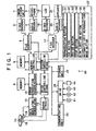
- FIG. 1 shows a configuration of a disk camcorder 50 to which the present invention is applied.
- a video signal from an image pickup unit 1 including an image pickup device such as a CCD (charge-coupled device), a CMOS (complementary metal-oxide semiconductor) or the like is inputted to a video encoder 2.
- the video encoder 2 compression-codes the video signal inputted thereto.
- an audio signal is inputted from a microphone 3 to an audio encoder 4.
- the audio encoder 4 compression-codes the audio signal inputted thereto.
- a method of compression-coding the video signal and the audio signal includes MPEG (Moving Picture Experts Group), for example.
- the compression-coded video data and audio data outputted from the video encoder 2 and the audio encoder 4 are supplied to a file generator 5.
- the file generator 5 is controlled by a system controlling micon (hereinafter "microcomputer” is simply referred to as “micon") 8.
- the file generator 5 converts the coded video data and audio data into a video elementary stream and an audio elementary stream so that the video data and audio data have a file structure capable of being handled by computer software for reproducing moving pictures and the like in synchronism without using special hardware. Also, the file generator 5 multiplexes the video elementary stream and the audio elementary stream to generate one file.
- the file generated by the file generator 5 is sequentially written to a memory 6 via a memory controller 7.
- the memory controller 7 reads the file generated by the file generator 5 from the memory 6.
- a coding transfer rate of the file is lower than a transfer rate of data being written to the disk, for example about 1/2 of the transfer rate of data being written to the disk.
- the file read from the memory 6 via the memory controller 7 is supplied to an error correction encoder/decoder 10.
- the error correction encoder/decoder 10 once writes the file to a memory 9, subjects the file to interleaving processing, generates redundant data of error correcting code, and then reads the data having the redundant data added thereto from the memory 9. Then, an output of the error correction encoder/decoder 10 is supplied to a data modulator/demodulator 12.
- the data modulator/demodulator 12 modulates the data so as to facilitate clock extraction at a time of reproduction and prevent problems such as intersymbol interference and the like.
- the data modulator/demodulator 12 outputs a signal for driving an optical pickup 16.
- the optical pickup 16 applies a laser beam for recording to the optical disk 14.
- the data is thus recorded on the optical disk 14.
- the optical disk 14 is rotated by a motor 15 at CLV (constant linear velocity), CAV (constant angular velocity), or ZCAV (zone CLV).
- the intermittent data read from the memory controller 7 is recorded onto the optical disk 14, continuous recording operation is not performed normally.
- the recording operation is interrupted after a given amount of data is recorded, and a standby state is maintained until a next recording request. Thus, the recording operation is performed intermittently.
- a drive controlling micon 11 issues a request to a servo circuit 13 to control a disk drive as a whole and thus perform the recording operation.
- the servo circuit 13 effects servo control of movement in a direction of a radius of the disk, tracking servo control, and focus servo control on the optical pickup 16, and also effects spindle servo control on the motor 15.
- the system controlling micon 8 is controlled by a user operating an operating input unit 22.
- the optical disk 14 such for example as a DVD (Digital Versatile Disk) is loaded into the disk camcorder 50, in response to an input signal from the operating input unit 22 having a reproduction button 31, a cue button 32, a review button 33, a stop button 34, a disk ejection button 35, an automatic edit reproduction mode button 36, and the like
- the system controlling micon 8 outputs a request to the drive controlling micon 11, and then the drive controlling micon 11 outputs a request to the servo circuit 13 to control the disk drive as a whole.
- the optical pickup 16 irradiates the optical disk 14 with a laser beam for reproduction, and converts light reflected from the optical disk 14 into a reproduced signal by a photodetector in the optical pickup 16.
- the servo circuit 13 detects a tracking error and a focus error from an output signal of the photodetector in the optical pickup 16, and effects control to position the reading laser beam on a track and focus the reading laser beam on the track.
- the servo circuit 13 also controls the movement of the optical pickup 16 in the direction of the radius of the disk to reproduce data at a desired position on the optical disk 14.
- the optical pickup 16 supplies the data modulator/demodulator 12 with the reproduced signal at a rate higher than a transfer rate of an image file, for example twice the transfer rate. In this case, continuous reproduction is not performed normally. Intermittent reproduction is performed in which the reproduction operation is interrupted after a given amount of data is reproduced and a standby state is maintained until a next reproduction request.
- the data modulator/demodulator 12 demodulates the reproduced signal supplied from the optical pickup 16 to the data modulator/demodulator 12, and then supplies the demodulated reproduced signal to the error correction encoder/decoder 10.
- the error correction encoder/decoder 10 once writes the demodulated reproduced data to the memory 9, and performs deinterleaving processing and error correction processing.
- the memory controller 7 writes the reproduced data after the error correction to the memory 6.
- the reproduced data written to the memory 6 is outputted to a file decoder 17 in response to a request from the system controlling micon 8 in accordance with synchronization timing in demultiplexing video data and audio data.
- the system controlling micon 8 monitors an amount of data reproduced from the optical disk 14 and written to the memory 6 and an amount of data read from the memory 6 and outputted to the file decoder 17, and controls the memory controller 7 and the drive controlling micon 11 to read data from the optical disk 14 such that the memory 6 does not overflow or underflow.
- the file decoder 17 separates the reproduced data into a video elementary stream and an audio elementary stream under control of the system controlling micon 8.
- the video elementary stream is supplied to a video decoder 18, and the audio elementary stream is supplied to an audio decoder 20.
- the video elementary stream and the audio elementary stream from the file decoder 17 are outputted so as to synchronize with each other.
- the video decoder 18 and the audio decoder 20 each perform decoding for compression coding.
- the video decoder 18 and the audio decoder 20 then output a video output signal to an LCD (liquid crystal display) 19 and an audio output signal to a speaker 21, respectively, whereby video and audio are reproduced.
- LCD liquid crystal display
- the optical disk 14 having data recorded thereon is removable, and is therefore reproducible by another apparatus.
- a personal computer operating with software for reproducing image data as mentioned above can read the data recorded on the optical disk 14 and reproduce the recorded video and audio data.
- the present invention is applicable to a case where only video data or only audio data is handled.
- system controlling micon 8 is connected with a communicating unit 24 for communicating data via a network typified by the Internet and a storage unit 23 formed by a semiconductor memory or the like for storing various data such as a program and the like.
- system controlling micon 8 is connected as required with a drive 25 for reading and writing data from and to a recording medium such as a magnetic disk 41, an optical disk 42, a magneto-optical disk 43, a semiconductor memory 44 or the like.
- a computer program for making the disk camcorder 50 perform predetermined operation is supplied to the disk camcorder 50 in a state of being stored on the magnetic disk 41 (including floppy disks), the optical disk 42 (including CD-ROM (Compact Disc-Read Only Memory) and DVD (Digital Versatile Disc)), the magneto-optical disk 43 (including MD (Mini Disc)), or the semiconductor memory 44.
- the computer program is read by the drive 25 and installed in the semiconductor memory included in the storage unit 23. According to an instruction of the system controlling micon 8 which instruction corresponds to a command inputted from a user to the operating input unit 22, the computer program installed in the storage unit 23 is loaded from the storage unit 23, and then executed.
- the automatic edit processing program determines whether an instruction to turn on power to a main body (disk camcorder 50) is given on the basis of a signal from the operating input unit 22.
- the automatic edit processing program determines that no instruction to turn on the power to the main body is given
- the automatic edit processing program holds the processing at the step S1, and continues the processing until an instruction to turn on the power is given.
- the automatic edit processing program determines that an instruction to turn on the power to the main body is given, the automatic edit processing program advances the processing to a step S2.
- the automatic edit processing program determines whether an optical disk 14 is loaded into the main body.
- the automatic edit processing program holds the processing at the step S2, and continues the processing until an optical disk 14 is loaded into the main body.
- the automatic edit processing program advances the processing to a step S3
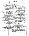
- the automatic edit processing program determines whether the reproduction button 31 of the operating input unit 22 is pressed.
- the automatic edit processing program determines that the reproduction button 31 is not pressed, the automatic edit processing program holds the processing at the step S3, and continues the processing until the reproduction button 31 is pressed.
- the automatic edit processing program determines that the reproduction button 31 is pressed, the automatic edit processing program advances the processing to a step S4 to detect a reproduction start point (a frame at which reproduction is started).
- the automatic edit processing program determines whether the reproduction start point is situated within an overrun region (a certain time before and after a scene change point (within about a few seconds)). When the automatic edit processing program determines that the reproduction start point is situated within the overrun region, the automatic edit processing program determines that the difference between the nearest start point of a scene and the reproduction start point is within an error range of operating input by the user.
- the automatic edit processing program advances the processing to a step S6 to set the reproduction start point to the start point of the scene (set a frame at the start point of the scene as the reproduction start point).
- length of an optimum overrun region varies depending on response of the apparatus, speed of cue (fast forward) and review (rewind) and the like. That is, the overrun region in this case refers to a distance (time) from an instruction for a stop (or reproduction) given by the user during a cue or review to an actual stop (or reproduction).
- the automatic edit processing program stores the reproduction start point in the memory 6.
- the automatic edit processing program advances the processing to a step S8.
- the automatic edit processing program determines whether the cue button 32 or the review button 33 of the operating input unit 22 is pressed.
- the automatic edit processing program advances the processing to a step S9 to detect a reproduction end point (a frame being reproduced in timing in which the cue button 32 or the review button 33 is pressed).
- the automatic edit processing program determines whether the reproduction end point is situated within an overrun region.
- the automatic edit processing program at a step S11 determines that the difference between the nearest end point of a scene and the reproduction end point is within an error range of operating input by the user, and sets the reproduction end point to the end point of the scene (sets a frame at the end point of the scene as the reproduction end point).
- the automatic edit processing program determines at the step S10 that the reproduction end point is not situated within the overrun region, the processing at the step S11 is skipped.
- the automatic edit processing program stores the reproduction end point in the memory 6.
- the automatic edit processing program advances the processing to a step S13.
- the automatic edit processing program determines at the step S13 that the stop button 34 is not pressed, the automatic edit processing program advances the processing to a step S21 to determine whether the reproduction button 31 is pressed.
- the automatic edit processing program determines that the reproduction button 31 is not pressed, the scene is still in the process of the cue or review, and thus the automatic edit processing program returns the processing to the step S13 and holds the processing until the stop button 34 or the reproduction button 31 is pressed.
- the automatic edit processing program determines that the reproduction button 31 is pressed, a scene is reproduced again, and thus the automatic edit processing program returns the processing to the step S4 to perform processing for storing a reproduction start point.
- the automatic edit processing program determines at the step S8 that the cue button 32 or the review button 33 is not pressed, the automatic edit processing program advances the processing to a step S15 to determine whether the stop button 34 of the operating input unit 22 is pressed.
- the automatic edit processing program determines at the step S15 that the stop button 34 is not pressed, the scene is still being reproduced, and thus the automatic edit processing program returns the processing to the step S8 and holds the processing until the cue button 32 or the review button 33 is pressed or until the stop button 34 is pressed (the reproduction is ended) .
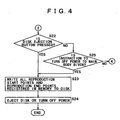
- the automatic edit processing program determines that the reproduction is ended.
- the automatic edit processing program detects a reproduction end point (a frame being reproduced in timing in which the stop button is pressed).
- the automatic edit processing program determines whether the reproduction end point is situated within an overrun region.
- the automatic edit processing program determines at the step S17 that the reproduction end point is situated within the overrun region, the automatic edit processing program determines that the difference between the end point of a scene and the reproduction end point is within an error range of operating input by the user, and advances the processing to a step S18.
- the automatic edit processing program sets the reproduction end point to the end point of the scene.
- the automatic edit processing program stores the reproduction end point in the memory 6.
- the automatic edit processing program determines at a step S14 whether a time from the reproduction start point to the reproduction end point is three seconds (generally a shortest shooting time) or more. When the automatic edit processing program determines that the time from the reproduction start point to the reproduction end point is three seconds or more, the automatic edit processing program determines that the scene has been reproduced, and then advances to processing at a step S22.
- the automatic edit processing program determines that the time from the reproduction start point to the reproduction end point is not three seconds or more (is less than three seconds)
- the automatic edit processing program determines that the scene has not been reproduced, and then advances to processing at a step S20 to erase the data of the reproduction start point and the reproduction end point stored at the step S7 and the step S12 or S19. Thereafter the processing proceeds to the step S22.
- the automatic edit processing program determines whether the disk ejection button 35 of the operating input unit 22 is pressed.
- the automatic edit processing program advances the processing to a step S23.
- the automatic edit processing program determines that the disk ejection button 35 is not pressed, the automatic edit processing program advances the processing to a step S25 to determine whether an instruction to turn off the power to the main body is given.
- the automatic edit processing program determines that an instruction to turn off the power to the main body is given, the automatic edit processing program advances the processing to the step S23.
- the processing returns to the step S3 to repeat the processing from the step S3 on down. That is, the above-described processing is repeated until the disk is ejected from the main body or until the power to the main body is turned off.
- the automatic edit processing program records all reproduction start points and reproduction end points registered in the memory 6 in Play Data 81 (to be described later with reference to FIG. 5 ) of the optical disk 14. Then, at a step S24, the automatic edit processing program ejects the optical disk 14 or turns off the power, and thereby ends the processing.
- buttons is pressed in the above-described processing means "a state after the button is pressed.” That is, for example “is the reproduction button pressed?" means “is the disk camcorder in a reproducing state?.”
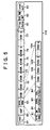
- a structure of a disk file written in the VR format on DVD-RW in the processing of FIGS. 2 to 4 will be described with reference to FIG. 5 .
- a Lead in 61 corresponds to an innermost circumference of the disk
- a Lead out 83 corresponds to an outermost circumference of the disk.
- the Lead in 61 describes a disk type, a format, a recording method and the like.
- a UDF (Universal Disk Format) 62 describes a file system.
- An RTR_VMG (Real Time Recording Video Manager) 63 has various management information of the VR format recorded therein.
- VOBs (Video Objects) 71 to 77 store real video data and audio data.
- the RTR_VMG 63 will be described in detail.
- the RTR_VMG 63 includes seven information tables. The following four tables pertinent to the present invention will be described below.
- An RTR_VMGI (Real Time Recording Video Manager Information) 91 describes address information of the information tables within the RTR_VMG 63, a date and time of creation of a play list, a storage location of the list (location of a user-defined PGCI) and other basic information related to Real Time Recording.
- An M_AVFIT (Movie AV File Information Table) 92 describes video attributes such for example as a VOB compression format, aspect ratio, and resolution, audio attributes such for example as a compression format, a number of channels, and transfer rate, and Time Map information.
- An ORG_PGCIT (Original Program Chain Information Table) 93 describes programs in original reproduction order. Start points and end points of a VOB1 71, a VOB2 72, a VOB3 73, a VOB4 74, a VOB5 75, a VOB6 76, ..., a VOBn 77 in recording order are sequentially described in a Cell1 111, a Cell2 112, a Cell3 113, a Cell4 114, ..., a Celln 117 corresponding to the VOB1 71 to the VOBn 77, respectively, within the ORG_PGCIT 93, as shown in FIG. 6 .
- a continuous group of Cells is referred to as a program (PG).
- PG A continuous group of Cells
- a PG1 141 includes the Cell1 111, the Cell2 112, the Cell3 113, the Cell4 114, ..., the Celln 117
- a PG2 142 includes a Celln+1 121, a Celln+2 122, a Celln+3 123, a Celln+4 124, ..., a Celln+n 127.
- the reproduction order is Cell number order (program number order).
- a UD_PGCIT (User Defined Program Chain Information Table) 94 includes a plurality of PGCIs defined by the user, and is used for editing and the like.
- a Cell within the UD_PGCIT 94 can describe an arbitrary start point and an arbitrary end point in VOBU (VOB Unit (corresponding to one GOP in MPEG)) unit within a VOB specified by the user.
- VOBU VOB Unit (corresponding to one GOP in MPEG)
- a Cell1 151 describes an arbitrary start point and an arbitrary end point in VOBU unit as a VOBU1 101 to a VOBUm 104 within a VOB1 71.
- Such Cells are brought together consecutively to form a program PG1 171.
- a list (play list) in the reproduction order (for example the Cell1 151, a Cell2 152, a Cell3 153, a Cell4 154, ..., a Celln 155) is described in PGCI.
- Play Data 81 describes, in VOBU unit, a reproduction start point and a reproduction end point of VOBU units reproduced by the disk camcorder 50.
- the disk camcorder 50 performs reproduction on the basis of the ORG_PGCIT 93 as shown in flowcharts of FIGS. 2 to 4 , the reproduction start point and the reproduction end point are described in the Play Data 81 in the processing at the step S23. Editing is performed on the basis of the reproduction start point and the reproduction end point, and the reproduction start point and the reproduction end point after the editing are described in the UD_PGCIT 94.
- a VOBU corresponding to a Cell in the ORG_PGCIT 93 and the UD_PGCIT 94 is reproduced with reference to a Time MAP within the M_AVFIT 92 where an address, size, and reproduction time of the VOBU are defined.
- the RTR_VMG 63, the VOB1 71 to the VOBn 77, and the Play Data 81 can be assigned a start point, an end point, and size arbitrarily by the UDF.
- the data can be newly set in another location.
- the automatic edit processing program reads the reproduction start point and the reproduction end point written to the Play Data 81 ( FIG. 5 ) of the optical disk 14 at the step S23 in FIG. 4 .
- the automatic edit processing program determines whether an edit rule is specified by the user. For example, the user can specify an edit rule that a length defined by the reproduction start point and the reproduction end point be obtained as either a longest range, a shortest range, or an average range.
- the automatic edit processing program determines that an edit rule is specified by the user, the automatic edit processing program advances the processing to a step S43 to obtain the specified edit rule.
- the automatic edit processing program determines at the step S42 that no edit rule is specified by the user, the automatic edit processing program advances the processing to a step S46 to obtain a default edit rule.
- a default edit rule In the above-mentioned example, either the longest range, the shortest range, or the average range is predefined as a default rule, and the default rule is obtained.
- the automatic edit processing program determines edit points from the reproduction start point and the reproduction end point written in the Play Data 81 of the optical disk 14 on the basis of the obtained edit rule. That is, on the basis of the obtained rule, points that make the longest range, the shortest range, or the average range are determined as edit points (an edit start point and an edit end point).
- the automatic edit processing program records the edit points determined at the step S44 in the UD_PGCIT 94 of the optical disk 14. The automatic edit processing program then ends the processing.
- FIG. 9 An example in which an editor performs automatic editing by using the automatic edit program according to the present invention and reproducing an image file three times will next be described with reference to FIG. 9 .
- hatched portions represent overrun regions, and portions enclosed by a circle represent a reproduction for less than the generally shortest shooting time (three seconds in this case, but may be another value).
- a reproduction is performed from a start of a scene A to a vicinity of a start of a scene B.
- a cue is performed to a vicinity of a start of a scene C.
- the scene C is reproduced for a short time, and at a next step S64, a review is performed to the vicinity of the start of the scene C.
- a reproduction is performed to a middle point in the scene C, and at a step S66, a cue is performed through an entire scene D to a vicinity of a start of a scene E.
- a step S67 the scene E is reproduced for a very short time (less than three seconds).
- a cue is performed to a middle point in the scene E directly after the step S67.
- a reproduction is performed from a middle point in the scene E, and is continued as it is to a middle point in a scene F.
- the scene B, a portion after the middle point in the scene C, the scene D, and a portion from the start to the middle point of the scene E are not reproduced.
- the photographer does not consider these ranges of the scenes very important.
- a reproduction is performed from the scene A to the vicinity of the start of the scene B.
- a cue is performed to the vicinity of the start of the scene C.
- a reproduction is performed to a middle point in the scene C, and at a step S84, a cue is performed to a middle point in the scene E.
- a reproduction is performed to a middle point in the scene F.
- a reproduction is performed to a middle point of the scene A.
- a cue is performed through the scenes B, C, and D to a middle point in the scene E.
- a review is performed to a middle point in the scene E at a step S104.
- a reproduction is performed to a middle point in the scene F.
- a VOBU unit has a duration of 0.5 seconds, and an overrun region represents a scene change point ⁇ 3 seconds.
- the reproduction is performed from a VOBU1 of a VOB1 to a VOBU4 of a VOB2 (from the scene A to the vicinity of the start of the scene B). Since the VOBU4 of the VOB2 is within an overrun region, a reproduction start point of the VOB1 to be registered is the VOBU1, and a reproduction end point of the VOB1 is a VOBU40, which is an end of the VOB1 (scene A). That is, a section 181 from the VOBU1 to the VOBU40 is registered as a reproduced section.
- a section from a VOBU20 of the VOB2 to a VOBU40 of a VOB3 is reproduced. Since the VOBU20 of the VOB2 is within an overrun region, the VOBU20 of the VOB2 is not registered as a reproduction start point; a VOBU1 of the VOB3, which is the start of the VOB3 (scene C), is registered as a reproduction start point. The VOBU40 of the VOB3 is registered as it is as a reproduction end point. That is, in this case, a section 182 from the VOBU1 to the VOBU40 of the scene C is registered as a reproduced section.
- the reproduction is performed from a VOBU5 to a VOBU10 of a VOB5 (a very short section of the scene E).
- the reproduction time is less than three seconds (the generally shortest reproduction time)
- the reproduction is performed from a VOBU35 of a VOB5 to a VOBU25 of a VOB6 (from the middle point in the scene E to the middle point in the scene F). Therefore, the VOBU35 of the VOB5 (scene E) is registered as a reproduction start point, and the VOBU25 of the VOB6 (scene F) is registered as a reproduction end point. That is, a section 183 from the VOBU35 to a VOBU46 of the VOB5 and a section 184 from a VOBU1 to the VOBU25 of the VOB6 are registered as a reproduced section.
- accumulated data as shown in FIG. 9 is stored in the Play Data 81 of the optical disk 14.
- reproduced sections registered as a result of the second reproduction are the scene A, a section from the start of the scene C (because the reproduction start point is in the overrun region) to the end point of the reproduction, and reproduced sections of the scene E and the scene F.
- Reproduced sections registered as a result of the third reproduction are the scene A, and sections of the scene E and the scene F which sections are reproduced at the step S105. Since a section of the scene E which section has been reproduced at the step S103 is of a duration less than three seconds, it is not determined that the section has been reproduced, and the section is not registered.
- FIG. 11 shows an example of a table of data accumulated in the Play Data 81 of the optical disk 14.
- VOB n four bytes of data 201
- VBU_S four bytes of data 202
- VOBU_E four bytes of data 203
- Reserve 204 for future use.
- a total of 16 bytes represents one reproduced section.
- images are automatically edited on the basis of the edit rule.
- a rule to set a reproduction start point and a reproduction end point to those of a longest reproduction time is selected as the edit rule, for example, reproduction based on a result of the edit is such as a first example of reproduction after an edit in FIG. 9 .
- reproduction based on a result of the edit is such as a second example of reproduction after an edit or a third example of reproduction after an edit, respectively, in FIG. 9 .
- an edit result more reflective of an intention of the photographer can be obtained by accumulating a plurality of data, such as data of two reproductions, three reproductions or the like.
- a weighting rule can be set.
- the scene C is reproduced less frequently than the scene A, the scene E, and the scene F, and therefore the scene C can be assigned a smaller weight than the scene A, the scene E, and the scene F.
- the automatic edit processing program sets an automatic edit reproduction mode.
- the automatic edit processing program reads the edit points recorded in the UD_PGCIT 94 in FIG. 5 from the optical disk 14. The edit points are recorded by the processing at the step S45 in FIG. 8 .
- the automatic edit processing program reproduces edited images on the basis of the edit points with reference to the Time MAP of the M_AVFIT 92 in FIG. 5 where the VOBU address, size, and reproduction time are defined. Thus, reproduction as shown as the first to fourth examples of reproduction after editing in FIG. 9 is performed.
- the system controlling micon 8 outputs a request to reproduce the read edit point to the drive controlling micon 11.
- the drive controlling micon 11 controls the servo circuit 13 to move the optical pickup 16 to the edit point.
- the optical pickup 16 irradiates the position of the edit point on the optical disk 14 with a laser beam for reproduction, and converts light reflected from the optical disk 14 into a reproduced signal by the photodetector.
- the reproduced signal is sequentially supplied to the data modulator/demodulator 12 and the error correction encoder/decoder 10 to be subjected to demodulation, deinterleaving processing, and error correction processing.
- the memory controller 7 once writes the reproduced signal as reproduced data to the memory 6.
- the reproduced data is supplied to the file decoder 17 to be separated into a video elementary stream and an audio elementary stream.
- the video elementary stream is supplied to the video decoder 18, and the audio elementary stream is supplied to the audio decoder 20 such that the video elementary stream and the audio elementary stream are synchronized with each other.
- the video decoder 18 and the audio decoder 20 each perform decoding for compression coding.
- the video decoder 18 and the audio decoder 20 then output a video output signal to the LCD (liquid crystal display) 19 and an audio output signal to the speaker 21, respectively.
- LCD liquid crystal display
- the present invention is applicable to apparatus for reproducing contents such as video, audio and the like when the contents are recorded on an information recording medium such as a disk, a tape, a semiconductor memory or the like.
- the series of processes described above can be carried out not only by hardware but also by software.
- a program comprising the software is installed from a network or a recording medium onto a disk camcorder that is incorporated in dedicated hardware, or for example a general-purpose disk camcorder or the like that can perform various functions by installing various programs thereon.
- the recording medium is not only formed by packaged media distributed to users to provide the program separately from the apparatus proper, the packaged media comprising the magnetic disk 41, the optical disk 42, the magneto-optical disk 43, the magneto-optical disk 63, the semiconductor memory 44 or the like which has the program recorded thereon, but also formed by the memory 6, the semiconductor memory included in the storage unit 23 or the like which has the program recorded thereon and which is provided to the user in a state of being preincorporated in the apparatus proper.
- the steps describing the program recorded on the recording medium include not only processing carried out in time series in the described order but also processing carried out in parallel or individually and not necessarily in time series.
- a system refers to an apparatus as a whole formed by a plurality of apparatus.
Landscapes
- Engineering & Computer Science (AREA)
- Multimedia (AREA)
- Signal Processing (AREA)
- Television Signal Processing For Recording (AREA)
- Management Or Editing Of Information On Record Carriers (AREA)
- Signal Processing For Digital Recording And Reproducing (AREA)
Applications Claiming Priority (3)
| Application Number | Priority Date | Filing Date | Title |
|---|---|---|---|
| JP2002106803A JP3760467B2 (ja) | 2002-04-09 | 2002-04-09 | コンテンツ再生装置および方法、記録媒体、並びにプログラム |
| JP2002106803 | 2002-04-09 | ||
| PCT/JP2003/004382 WO2003085971A1 (fr) | 2002-04-09 | 2003-04-07 | Dispositif et procede de reproduction de contenu, support d'enregistrement et programme |
Publications (3)
| Publication Number | Publication Date |
|---|---|
| EP1494471A1 EP1494471A1 (en) | 2005-01-05 |
| EP1494471A4 EP1494471A4 (en) | 2007-06-06 |
| EP1494471B1 true EP1494471B1 (en) | 2009-07-15 |
Family
ID=28786443
Family Applications (1)
| Application Number | Title | Priority Date | Filing Date |
|---|---|---|---|
| EP03745937A Expired - Lifetime EP1494471B1 (en) | 2002-04-09 | 2003-04-07 | Content reproduction device and method, recording medium, and program |
Country Status (8)
Families Citing this family (5)
| Publication number | Priority date | Publication date | Assignee | Title |
|---|---|---|---|---|
| TWI395591B (zh) * | 2004-04-01 | 2013-05-11 | Oncothyreon Inc | 黏液性糖蛋白(muc-1)疫苗 |
| JP4572740B2 (ja) * | 2005-05-24 | 2010-11-04 | 船井電機株式会社 | 光ディスク装置 |
| KR100701382B1 (ko) * | 2005-07-08 | 2007-03-28 | 엘지전자 주식회사 | 광디스크 장치에서의 타이틀 선별 재생방법 |
| US20090132924A1 (en) * | 2007-11-15 | 2009-05-21 | Yojak Harshad Vasa | System and method to create highlight portions of media content |
| US10230878B2 (en) | 2016-04-08 | 2019-03-12 | Tdk Taiwan Corp. | Camera module |
Family Cites Families (14)
| Publication number | Priority date | Publication date | Assignee | Title |
|---|---|---|---|---|
| JPH06338170A (ja) * | 1993-05-26 | 1994-12-06 | Canon Inc | Vtr編集装置 |
| JP3154921B2 (ja) * | 1995-06-09 | 2001-04-09 | 富士通株式会社 | ビデオ・オン・デマンドシステムにおける映像再生位置割り出し方式 |
| US5953481A (en) * | 1996-01-08 | 1999-09-14 | Canon Kabushiki Kaisha | Reproducing apparatus having an editing function |
| US6546189B1 (en) | 1996-11-15 | 2003-04-08 | Hitachi, Ltd. | Method and apparatus for editing compressed moving pictures and storage medium |
| JP3411184B2 (ja) * | 1997-05-14 | 2003-05-26 | 松下電器産業株式会社 | 動画エディットシステム |
| JP3613543B2 (ja) * | 1997-11-11 | 2005-01-26 | 株式会社日立国際電気 | 動画像編集装置 |
| JP3607486B2 (ja) | 1998-01-21 | 2005-01-05 | 株式会社東芝 | 情報記録再生装置 |
| JP4154799B2 (ja) | 1998-04-28 | 2008-09-24 | 株式会社日立製作所 | 圧縮動画像編集装置および記憶媒体 |
| JP4341111B2 (ja) * | 1999-08-18 | 2009-10-07 | ソニー株式会社 | 記録再生装置および記録再生方法 |
| JP4592844B2 (ja) * | 1999-08-27 | 2010-12-08 | ソニー株式会社 | データ再生装置、データ再生方法 |
| JP3073485U (ja) * | 2000-05-24 | 2000-11-30 | 船井電機株式会社 | ディスク装置 |
| JP2002016866A (ja) * | 2000-06-30 | 2002-01-18 | Toshiba Corp | ファイル管理システムおよびステータス情報送信システム |
| US7333610B2 (en) * | 2000-08-11 | 2008-02-19 | Nds Ltd | System and method for pre-encryption of transmitted content |
| US20030049014A1 (en) * | 2001-09-07 | 2003-03-13 | Tri-Vision Electronics Inc. | Method and apparatus for playing digital media and digital media for use therein |
-
2002
- 2002-04-09 JP JP2002106803A patent/JP3760467B2/ja not_active Expired - Fee Related
-
2003
- 2003-04-07 WO PCT/JP2003/004382 patent/WO2003085971A1/ja active Application Filing
- 2003-04-07 EP EP03745937A patent/EP1494471B1/en not_active Expired - Lifetime
- 2003-04-07 CN CNB038008017A patent/CN1274144C/zh not_active Expired - Fee Related
- 2003-04-07 US US10/479,928 patent/US7546021B2/en not_active Expired - Fee Related
- 2003-04-07 AU AU2003236282A patent/AU2003236282A1/en not_active Abandoned
- 2003-04-07 DE DE60328369T patent/DE60328369D1/de not_active Expired - Lifetime
- 2003-04-07 KR KR1020037016046A patent/KR100994895B1/ko not_active Expired - Fee Related
-
2009
- 2009-04-24 US US12/429,213 patent/US8295685B2/en not_active Expired - Fee Related
Also Published As
| Publication number | Publication date |
|---|---|
| DE60328369D1 (de) | 2009-08-27 |
| US7546021B2 (en) | 2009-06-09 |
| AU2003236282A1 (en) | 2003-10-20 |
| JP3760467B2 (ja) | 2006-03-29 |
| US20040264320A1 (en) | 2004-12-30 |
| KR100994895B1 (ko) | 2010-11-16 |
| CN1545806A (zh) | 2004-11-10 |
| CN1274144C (zh) | 2006-09-06 |
| JP2003304487A (ja) | 2003-10-24 |
| US8295685B2 (en) | 2012-10-23 |
| EP1494471A4 (en) | 2007-06-06 |
| EP1494471A1 (en) | 2005-01-05 |
| KR20040099102A (ko) | 2004-11-26 |
| US20090208182A1 (en) | 2009-08-20 |
| WO2003085971A1 (fr) | 2003-10-16 |
Similar Documents
| Publication | Publication Date | Title |
|---|---|---|
| EP1236203B1 (en) | A method of disaster recovery for re-writable disk media | |
| US7099563B1 (en) | Multichannel recording device and method | |
| EP1236349B1 (en) | Method for editing source video to slow motion or fast motion on the recordable media | |
| US20060013562A1 (en) | Recording method, recording device, and recording medium | |
| KR100579454B1 (ko) | 기록매체 및 이에 테스트 기록을 수행하는 장치 및 방법 | |
| US7333411B2 (en) | Optical recording method and optical recording device | |
| US8295685B2 (en) | Content reproduction device and method, recording medium, and program | |
| US20100111506A1 (en) | Method for creating, updating, and recording seamless presentation information of moving picture data in a rewritable recording medium | |
| US7480440B2 (en) | Optical disc recording apparatus and method thereof | |
| MXPA02004680A (es) | Eliminacion y restauracion para una edicion de un dvd de re-escritura. | |
| JP2003514334A (ja) | レコーダブルdvd編集のためのコピーの特徴 | |
| EP1241668A2 (en) | Method and apparatus for image recording and reproduction for plurality of media | |
| US7805059B2 (en) | Data recording method, data recording apparatus and image pick-up apparatus | |
| KR101040553B1 (ko) | 디스크 레코더에서의 데이터 분할 기록장치 및 방법 | |
| EP1331816B1 (en) | Method for editing source video to fast motion on the recordable media | |
| JP4429120B2 (ja) | 記録装置及び記録方法 | |
| KR100550692B1 (ko) | 디지털 데이터스트림의 탐색 제어방법 | |
| JP2005108316A (ja) | 情報記録装置及び情報記録方法 | |
| JP2004213729A (ja) | Dvd再生装置 | |
| JP2001084703A (ja) | 再生装置、再生方法及びコンピュータ読みとり可能な記憶媒体 | |
| JP2006127629A (ja) | 映像記録再生装置 |
Legal Events
| Date | Code | Title | Description |
|---|---|---|---|
| PUAI | Public reference made under article 153(3) epc to a published international application that has entered the european phase |
Free format text: ORIGINAL CODE: 0009012 |
|
| 17P | Request for examination filed |
Effective date: 20031202 |
|
| AK | Designated contracting states |
Kind code of ref document: A1 Designated state(s): AT BE BG CH CY CZ DE DK EE ES FI FR GB GR HU IE IT LI LU MC NL PT RO SE SI SK TR |
|
| AX | Request for extension of the european patent |
Extension state: AL LT LV MK |
|
| A4 | Supplementary search report drawn up and despatched |
Effective date: 20070508 |
|
| 17Q | First examination report despatched |
Effective date: 20071123 |
|
| GRAP | Despatch of communication of intention to grant a patent |
Free format text: ORIGINAL CODE: EPIDOSNIGR1 |
|
| GRAS | Grant fee paid |
Free format text: ORIGINAL CODE: EPIDOSNIGR3 |
|
| GRAA | (expected) grant |
Free format text: ORIGINAL CODE: 0009210 |
|
| AK | Designated contracting states |
Kind code of ref document: B1 Designated state(s): DE FR GB NL |
|
| REG | Reference to a national code |
Ref country code: GB Ref legal event code: FG4D |
|
| REF | Corresponds to: |
Ref document number: 60328369 Country of ref document: DE Date of ref document: 20090827 Kind code of ref document: P |
|
| NLR4 | Nl: receipt of corrected translation in the netherlands language at the initiative of the proprietor of the patent | ||
| PLBE | No opposition filed within time limit |
Free format text: ORIGINAL CODE: 0009261 |
|
| STAA | Information on the status of an ep patent application or granted ep patent |
Free format text: STATUS: NO OPPOSITION FILED WITHIN TIME LIMIT |
|
| 26N | No opposition filed |
Effective date: 20100416 |
|
| REG | Reference to a national code |
Ref country code: GB Ref legal event code: 746 Effective date: 20120702 |
|
| PGFP | Annual fee paid to national office [announced via postgrant information from national office to epo] |
Ref country code: DE Payment date: 20120420 Year of fee payment: 10 Ref country code: NL Payment date: 20120425 Year of fee payment: 10 |
|
| REG | Reference to a national code |
Ref country code: DE Ref legal event code: R084 Ref document number: 60328369 Country of ref document: DE Effective date: 20120614 |
|
| PGFP | Annual fee paid to national office [announced via postgrant information from national office to epo] |
Ref country code: FR Payment date: 20120507 Year of fee payment: 10 Ref country code: GB Payment date: 20120419 Year of fee payment: 10 |
|
| REG | Reference to a national code |
Ref country code: NL Ref legal event code: V1 Effective date: 20131101 |
|
| GBPC | Gb: european patent ceased through non-payment of renewal fee |
Effective date: 20130407 |
|
| PG25 | Lapsed in a contracting state [announced via postgrant information from national office to epo] |
Ref country code: GB Free format text: LAPSE BECAUSE OF NON-PAYMENT OF DUE FEES Effective date: 20130407 Ref country code: DE Free format text: LAPSE BECAUSE OF NON-PAYMENT OF DUE FEES Effective date: 20131101 |
|
| REG | Reference to a national code |
Ref country code: FR Ref legal event code: ST Effective date: 20131231 |
|
| REG | Reference to a national code |
Ref country code: DE Ref legal event code: R119 Ref document number: 60328369 Country of ref document: DE Effective date: 20131101 |
|
| PG25 | Lapsed in a contracting state [announced via postgrant information from national office to epo] |
Ref country code: FR Free format text: LAPSE BECAUSE OF NON-PAYMENT OF DUE FEES Effective date: 20130430 Ref country code: NL Free format text: LAPSE BECAUSE OF NON-PAYMENT OF DUE FEES Effective date: 20131101 |