EP1494070A2 - Une méthode, un produit de logiciel et un appareil pour produire des structures auxiliaires utilisant une carte de champs d'image - Google Patents
Une méthode, un produit de logiciel et un appareil pour produire des structures auxiliaires utilisant une carte de champs d'image Download PDFInfo
- Publication number
- EP1494070A2 EP1494070A2 EP04253956A EP04253956A EP1494070A2 EP 1494070 A2 EP1494070 A2 EP 1494070A2 EP 04253956 A EP04253956 A EP 04253956A EP 04253956 A EP04253956 A EP 04253956A EP 1494070 A2 EP1494070 A2 EP 1494070A2
- Authority
- EP
- European Patent Office
- Prior art keywords
- contour
- generating
- assist
- assist features
- pattern
- Prior art date
- Legal status (The legal status is an assumption and is not a legal conclusion. Google has not performed a legal analysis and makes no representation as to the accuracy of the status listed.)
- Withdrawn
Links
Images


Classifications
-
- G—PHYSICS
- G03—PHOTOGRAPHY; CINEMATOGRAPHY; ANALOGOUS TECHNIQUES USING WAVES OTHER THAN OPTICAL WAVES; ELECTROGRAPHY; HOLOGRAPHY
- G03F—PHOTOMECHANICAL PRODUCTION OF TEXTURED OR PATTERNED SURFACES, e.g. FOR PRINTING, FOR PROCESSING OF SEMICONDUCTOR DEVICES; MATERIALS THEREFOR; ORIGINALS THEREFOR; APPARATUS SPECIALLY ADAPTED THEREFOR
- G03F7/00—Photomechanical, e.g. photolithographic, production of textured or patterned surfaces, e.g. printing surfaces; Materials therefor, e.g. comprising photoresists; Apparatus specially adapted therefor
- G03F7/20—Exposure; Apparatus therefor
-
- G—PHYSICS
- G03—PHOTOGRAPHY; CINEMATOGRAPHY; ANALOGOUS TECHNIQUES USING WAVES OTHER THAN OPTICAL WAVES; ELECTROGRAPHY; HOLOGRAPHY
- G03F—PHOTOMECHANICAL PRODUCTION OF TEXTURED OR PATTERNED SURFACES, e.g. FOR PRINTING, FOR PROCESSING OF SEMICONDUCTOR DEVICES; MATERIALS THEREFOR; ORIGINALS THEREFOR; APPARATUS SPECIALLY ADAPTED THEREFOR
- G03F1/00—Originals for photomechanical production of textured or patterned surfaces, e.g., masks, photo-masks, reticles; Mask blanks or pellicles therefor; Containers specially adapted therefor; Preparation thereof
- G03F1/36—Masks having proximity correction features; Preparation thereof, e.g. optical proximity correction [OPC] design processes
-
- G—PHYSICS
- G03—PHOTOGRAPHY; CINEMATOGRAPHY; ANALOGOUS TECHNIQUES USING WAVES OTHER THAN OPTICAL WAVES; ELECTROGRAPHY; HOLOGRAPHY
- G03F—PHOTOMECHANICAL PRODUCTION OF TEXTURED OR PATTERNED SURFACES, e.g. FOR PRINTING, FOR PROCESSING OF SEMICONDUCTOR DEVICES; MATERIALS THEREFOR; ORIGINALS THEREFOR; APPARATUS SPECIALLY ADAPTED THEREFOR
- G03F7/00—Photomechanical, e.g. photolithographic, production of textured or patterned surfaces, e.g. printing surfaces; Materials therefor, e.g. comprising photoresists; Apparatus specially adapted therefor
- G03F7/70—Microphotolithographic exposure; Apparatus therefor
- G03F7/70425—Imaging strategies, e.g. for increasing throughput or resolution, printing product fields larger than the image field or compensating lithography- or non-lithography errors, e.g. proximity correction, mix-and-match, stitching or double patterning
- G03F7/70433—Layout for increasing efficiency or for compensating imaging errors, e.g. layout of exposure fields for reducing focus errors; Use of mask features for increasing efficiency or for compensating imaging errors
- G03F7/70441—Optical proximity correction [OPC]
Definitions
- the technical field relates generally to a method, program product and apparatus for microlithography for generating assist features in accordance with an image field map.
- Lithographic apparatus can be used, for example, in the manufacture of integrated circuits (ICs).
- the mask may contain a circuit pattern corresponding to an individual layer of the IC, and this pattern can be imaged onto a target portion (e.g. , comprising one or more dies) on a substrate (silicon wafer) that has been coated with a layer of radiation-sensitive material (resist).
- a target portion e.g. , comprising one or more dies
- a substrate silicon wafer
- a layer of radiation-sensitive material resist
- a single wafer will contain a whole network of adjacent target portions that are successively irradiated via the projection system, one at a time.
- each target portion is irradiated by exposing the entire mask pattern onto the target portion in one go; such an apparatus is commonly referred to as a wafer stepper.
- each target portion is irradiated by progressively scanning the mask pattern under the projection beam in a given reference direction (the "scanning" direction) while synchronously scanning the substrate table parallel or anti-parallel to this direction.
- the projection system will have a magnification factor M (generally ⁇ 1)
- M magnification factor
- the speed V at which the substrate table is scanned will be a factor M times that at which the mask table is scanned.
- a mask pattern is imaged onto a substrate that is at least partially covered by a layer of radiation-sensitive material (resist).
- the substrate Prior to this imaging step, the substrate may undergo various procedures, such as priming, resist coating and a soft bake. After exposure, the substrate may be subjected to other procedures, such as a post-exposure bake (PEB), development, a hard bake and measurement/inspection of the imaged features.
- PEB post-exposure bake
- This array of procedures is used as a basis to pattern an individual layer of a device, e.g. , an IC.
- Such a patterned layer may then undergo various processes such as etching, ion-implantation (doping), metallization, oxidation, chemo-mechanical polishing, etc., all intended to finish off an individual layer. If several layers are required, then the whole procedure, or a variant thereof, will have to be repeated for each new layer. Eventually, an array of devices will be present on the substrate (wafer). These devices are then separated from one another by a technique such as dicing or sawing, whence the individual devices can be mounted on a carrier, connected to pins, etc.
- the projection system may hereinafter be referred to as the "lens;" however, this term should be broadly interpreted as encompassing various types of projection systems, including refractive optics, reflective optics, and catadioptric systems, for example.
- the radiation system may also include components operating according to any of these design types for directing, shaping or controlling the projection beam of radiation, and such components may also be referred to below, collectively or singularly, as a "lens.”
- the lithographic apparatus may be of a type having two or more substrate tables (and/or two or more mask tables). In such "multiple stage" devices the additional tables may be used in parallel, or preparatory steps may be carried out on one or more tables while one or more other tables are being used for exposures. Twin stage lithographic apparatus are described, for example, in US 5,969,441, incorporated herein by reference.
- the photolithographic masks referred to above comprise geometric patterns corresponding to the circuit components to be integrated onto a silicon wafer.
- the patterns used to create such masks are generated utilizing CAD (computer-aided design) programs, this process often being referred to as EDA (electronic design automation).
- EDA electronic design automation
- Most CAD programs follow a set of predetermined design rules in order to create functional masks. These rules are set by processing and design limitations.
- design rules define the space tolerance between circuit devices (such as gates, capacitors, etc.) or interconnect lines, so as to ensure that the circuit devices or lines do not interact with one another in an undesirable way.
- the design rule limitations are typically referred to as "critical dimensions" (CD).
- a critical dimension of a circuit can be defined as the smallest width of a line or hole or the smallest space between two lines or two holes. Thus, the CD determines the overall size and density of the designed circuit.
- Assist features in masks may be used to improve the image projected onto the resist and ultimately the developed device. Assist features are features that are not intended to appear in the pattern developed in the resist but are provided in the mask to take advantage of diffraction effects so that the developed image more closely resembles the desired circuit pattern. Assist features are generally "sub-resolution” or “deep sub-resolution,” meaning that they are smaller in at least one dimension than the smallest feature in the mask that will actually be resolved on the wafer. Assist features may have dimensions defined as fractions of the critical dimension. In other words, because the mask pattern is generally projected with a magnification of less than 1, e.g., 1/4 or 1/5, the assist feature on the mask may have a physical dimension larger than the smallest feature on the wafer.
- Scattering bars are lines with a subresolution width placed on one or both sides of an isolated feature to mimic proximity effects that occur in densely packed regions of a pattern.
- Serifs are additional areas of various shapes placed at the comers and ends of features, or the corners of rectangular features, to make the end of the line, or the comer, more nearly square or round, as desired (note that in this context assist features commonly referred to as "hammerheads" are regarded as being a form of serif). Further information on the use of scattering bars and serifs can be found in U.S. Pat. Nos.5,242,770 and 5,707,765, for example, which are incorporated herein by reference.
- one of the goals in integrated circuit fabrication is to faithfully reproduce the original circuit design on the wafer (via the mask), which is improved with the use of assist features.
- Placement of these assist features generally follows a pre-defined set of rules. Following this method, designers determine how to bias a line, for example, and placement of assist features is determined in accordance with a set of predetermined rules. When creating the set of rules, test masks are exposed to different illumination settings and NA settings, which are repeated. Based on the set of test masks, a set of rules is created for assist feature placement.
- rules generated utilizing a one-dimensional analysis are based on an analysis of parallel lines. Rules generated utilizing a one-and-a-half-dimensional analysis take into consideration spacing between two parallel lines, line width and lines in the vicinity of the parallel lines. The one-and-half-dimensional approach is often useful for non-uniform pitch between parallel lines. Obviously, the more factors considered, the more complex the rules become.
- the rule base approach does not adapt itself well to complicated designs where a two-dimensional analysis is preferred.
- a two-dimensional analysis is based on all of the factors considered in the one-dimensional analysis and the one-and-a-half dimensional analysis, but is further based on a full analysis of the surroundings, i.e. , an analysis of the full design layout or any portion thereof.
- rules based on a two-dimensional analysis are very difficult to formulate and express, and generally lead to very complicated multi-dimensional matrices. Often designers prefer to use a one-dimensional or one-and-a-half dimensional approach.
- the disclosed concepts include a method and program product for generating assist features for a pattern to be formed over a surface of a substrate.
- the steps include generating an image field map corresponding to the pattern, extracting characteristics of the image field map, and generating at least one assist feature for the pattern in accordance with the characteristics extracted.
- the image field map may correspond to a map showing changes in magnitude of intensity characteristics, interference characteristics, e-field characteristics, or intensity, interference or e-field characteristics that factor a characteristic or a limitation of a lithographic apparatus.
- a full analysis of the surroundings of the pattern are taken into consideration for generating assist features by utilizing an image field map. This is less complex and simple to administer, as opposed to a rule-based two-dimensional analysis.
- characteristics, such as contours, of the image field map are extracted at a predetermined threshold.
- a dominant axis of the contour is determined, and an assist features is oriented relative to the dominant axis. This may be repeated for other contours at the predetermined threshold, and even other contours at a different predetermined threshold.
- Generated assist features may be of a predetermined size, or assist features may be sized corresponding to their associated contours.
- assist features may be polygon-shaped and sized to closely surround a respective contour.
- the polygon-shape may be sized to fit within a respective contour. Even a combination of both polygon-shaped assist features sized to closely surround a respective contour and sized to fit within a respective contour may be utilized.
- extrema characteristics of the image field map may be identified. From each extrema is determined an axial direction of least curvature. Accordingly, an assist feature may be oriented with respect to each extrema in the axial direction.
- the assist features may be of a predetermined size, or even sized based on a predetermined threshold and corresponding contour extracted from the image field map.
- the disclosed concepts include an apparatus for generating a mask design utilizing assist features for a pattern to be formed over a surface of a substrate.
- the apparatus includes a radiation system for supplying a projection beam of radiation, an illuminator for receiving the projection beam of radiation and projecting an adjusted beam of radiation on a portion of the mask, and a projection system for imaging a corresponding irradiated portion of the mask onto a target portion of a substrate.
- the mask is formed utilizing assist features generated in accordance with a non-rule-based two-dimensional analysis of an image field map corresponding to the pattern.
- the apparatus comprises even further a computer system configured to generate assist features by generating the image field map corresponding to the pattern, extracting characteristics of the image field map, and generating at least one assist feature for the pattern in accordance with the characteristics extracted.
- the computer system is configured to generate an assist feature corresponding to a contour of the image field map at a predetermined threshold and the dominant axis of the contour.
- the computer system is further configured to generate an assist feature corresponding to an extremum of the image field map.
- the inventors have devised novel techniques for determining placement and size of assist features taking into consideration the true optical effects of a pattern to be formed over a surface of a substrate.
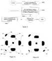
- Fig. 1 is an exemplary flow chart of a method for optimizing placement of assist features on a mask while taking into consideration the true optical effects on an entire pattern, or any portion thereof, to be formed over a surface of a substrate.
- pattern includes an entire pattern or any portion thereof.
- Step 100 an image field map is generated corresponding to a pattern or to be formed over a surface of a substrate.
- the image field map may generated by a simulator, or captured by illuminating a pattern to be formed over the surface of the substrate.
- image field map includes any type of image map that illustrates changes in magnitude of intensity characteristics, interference characteristics, e-field characteristics, or even an intensity map taking into account aberrations or any other characteristics or limitation of a lithographic apparatus, which is described later herein.
- the image field map includes any derivation of, or any combination of, these characteristics.
- an image field map may illustrate changes in the magnitude of the derivate of intensity.
- Fig. 2 illustrates an exemplary contact hole pattern 20 containing a plurality of contact holes 22 from which an image field map may be generated.
- this application shall not be limited to contact hole patterns such as the one illustrated, but includes other patterns, e.g., including line features, line features and contact holes, etc.
- the contact hole pattern 20 has been chosen for ease of illustration and explanation of the novel concepts disclosed herein.
- Fig. 3 illustrates an image field map 30 that was generated using the exemplary contact hole pattern 20 of Fig. 2, and corresponds to an image field map that may be generated from S100.
- the image field map 30 illustrates field lines (contour 32) based on influence of each of the plurality of contact holes 22. Also, this image field map 30 corresponds to an intensity map, and contours 34 correspond to certain magnitudes of intensity at the surface of the substrate being imaged
- S102 and S104 of Fig. 1 are described in detail in Embodiments 1-5, discussed below.
- S102 corresponds to S200 and S202 (Fig. 4) of Embodiment 1, S300 (Fig. 9) of Embodiment 2, S400 (Fig. 14) of Embodiment 3, S500 (Fig. 17) of Embodiment 4, and S600 and S602 (Fig. 18) of Embodiment 5.
- S104 corresponds to S204 (Fig. 4) of Embodiment 1, S302 (Fig. 9) of Embodiment 2, S402 (Fig. 14) of Embodiment 3, S504 (Fig. 17) of Embodiment 4, and S604-S608 (Fig. 18) of Embodiment 5.
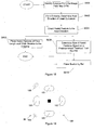
- Fig. 4 illustrates an exemplary flow diagram of the present embodiment
- these characteristics correspond to a contour 34 (a plurality of contours 34) at a predetermined threshold that is extracted.
- Fig. 5 illustrates a derivation 50 of the image field map 30 in which contour 34 at the predetermined threshold level has been extracted.
- contour 34 is shown in solid.
- a dominant axis of each contour 34 is determined.
- Techniques for determining a dominant axis of any shape are known to those of ordinary skill in the art.
- One method entails determining a dominant axis in accordance with a plurality of axes.
- Fig. 6 illustrates shape 60 and a plurality of axes 62 positioned on or near a centroid 64 of shape 60.
- any number of axes 62 may be utilized.
- Accuracy increases with an increase of the number of axes 62 utilized.
- processing time also increases.
- the dominant axis corresponds to the axis with the greatest overlap with shape 60. Therefore, in Fig. 6, axis 66 of the plurality of axes 62 corresponds to the dominant axes.
- assist features 70 of a predetermined size may be placed corresponding to each contour 34, and oriented with respect to the dominant axis (not shown) for its associated contour 34.
- assist features 72 may be sized relative to their associated contour 34 in which the assist feature 72 is placed.
- sized assist features 72 are oriented with respect to the dominant axis (not shown) for its associated contour 34.
- Assist features 70 may be sized according to respective contour 34, or assist features 72 may correspond to a predetermined size. Or a predetermined size of assist features 70 or 72 may vary in size relative to the length of the dominant axis (not shown) of the respective contour 34. It is again noted that in all embodiments, the final size of the assist feature must be such that the assist features are not imaged on the substrate.
- assist feature treatment may be determined by designer inspection, creating a test image, or even by simulation.
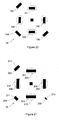
- the predetermined threshold may be changed to a different threshold, as in S208. For example, if a contour, such as contour 76 of Fig. 7, is too small to accurately generate an assist feature, a lower or higher predetermined threshold may be selected to expand the area of the contour 76.
- contour 38 of a different predetermined threshold may be extracted, as in S208. This extracted contour 80 is illustrated by Fig. 8. Accordingly, in S210, a dominant axis of contour 80 is determined. S204 is repeated for generating the corresponding assist feature 82.
- Steps S204 - S210 may be repeated until sufficient assist feature treatment is accomplished. Also, Steps S204 - S210 may be repeated for a range of thresholds, which may be selected for a sufficient assist feature treatment.
- embodiment 1 advantageously generates assist features for the image field map by factoring in characteristics of the entire pattern and avoids complicated computation characteristics of a two-dimensional rule-based approach.
- Fig. 9 illustrates an exemplary flow chart for generating assist features according to embodiment 2.
- S300 corresponds to S200 of Fig. S200.
- similar descriptions will not be repeated.
- Sizing of assist features according to Embodiment 2 differs from Embodiment 1. Instead of determining a dominant axis of contour 34, as in Embodiment 1, polygon-shaped assist features 70-75 are formed corresponding to an area of each of the respective contours 34.
- Embodiment 2 utilize an octagon-shaped assist feature 70-75.
- the inventors have found that octagon-shaped assist features 70-75 are preferred because angles at each of the vertices of the octagon-shaped assist features 70-75 are a multiple of 45 degrees. Therefore, geometric and mathematical analysis is easier with angles of multiples of 45 degrees.
- any number of sides of a polygon may be used. The greater number of sides of a polygon-shaped assist feature will increasingly match contour 34. However, computation is greatly increased.
- each contour 34 is enclosed by a polygon-shaped assist feature (octagon-shaped assist features 70-75). Therefore, as Fig. 10 illustrates, each assist feature 70-75 is sized to closely surround or enclose its respective contour 34.
- a regular octagon-shaped assist feature (not shown) is positioned to enclose a respective contour 34. Then, a side of the regular octagon-shaped assist feature (not shown) is adjusted until it intersects or nearly intersects an edge of its respective contour 34. This is repeated until all sides of the regular octagon-shaped contour (not shown) have been adjusted, and form an irregular octagon-shaped assist feature, such as those denoted by 70-75. Accordingly, in S302 each octagon-shaped assist feature 70-75 is placed corresponding to its respective contour 34 such that each octagon-shaped assist feature 70-75 closely surrounds its respective contour 34.
- S304 corresponds to S206 in Fig. 4.
- the predetermined threshold may be changed to a different threshold, as in S306.
- a contour such as contour 76 of Fig. 10 is too small for accurately generating an octagon-shaped assist feature
- a lower or higher predetermined threshold may be selected to expand the area of contour 76 for accurately generating an octagon-shaped assist feature.
- contour 38 of a different predetermined threshold may be extracted, as in S306. This extracted contour 110 is illustrated by Fig. 11. Accordingly, reverting back to S302, an octagon-shaped assist feature 112 is generated corresponding to contour 110.
- Steps S302 - S306 may be repeated until sufficient assist feature treatment is accomplished. Also, Steps S302 - S306 may be repeated for a range of predetermined thresholds.
- Embodiment 2 advantageously generates polygon-shaped assist features from the image field map that closely resemble its respective contour by factoring in characteristics of the entire pattern and avoids the complicated computation characteristic of a two-dimensional rule-based approach.
- Embodiment 3 utilizes polygon-shaped assist features similar to that of Embodiment 2. However, instead of enclosing a contour with a polygon-shaped assist feature, a polygon-shaped assist feature is formed within the contour. Even further, the polygon-shaped assist feature may be inscribed within the contour (vertices intersect the contour).
- Figs. 12 and 13 illustrate the advantages of each method.
- Fig. 12 illustrates an exemplary contour 120, a polygon-shaped assist feature 122 formed surrounding contour 120 in accordance with Embodiment 2, and a polygon-shaped assist feature 124 formed inside contour 120 in accordance with embodiment 3. Because of inner protrusions 126 of contour 120, polygon-shaped assist feature 122 formed surrounding contour 120 more closely matches its shape, as opposed to polygon-shaped assist feature 124 formed inside the contour 120. Conversely, Fig. 13 illustrates an exemplary contour 130, polygon-shaped assist feature 132 formed surrounding contour 130 in accordance with Embodiment 2, and polygon-shaped assist feature 134 formed inside the contour 130 in accordance with Embodiment 3. Because of the outer protrusions 136 of contour 130, polygon-shaped assist feature 132 formed within contour 130 more closely matches the shape of contour 130, as opposed to polygon-shaped assist feature 134 formed surrounding contour 130.
- Fig. 14 illustrates an exemplary flow chart for generating assist features according to embodiment 3.
- S400 corresponds to S300 of Fig. 9.
- similar descriptions will not be repeated.
- each octagon-shaped assist feature 150-155 (Fig. 15) is formed within its respective contour 34. Therefore, as Fig. 15 illustrates, each assist feature 150-155 is sized closely corresponding to an area of its respective contour 34.
- a regular octagon-shaped assist feature (not shown) is positioned relative to a respective contour 34.
- An edge of the regular octagon-shaped assist feature (not shown) is adjusted until the ends of the edge intersect or nearly intersect an edge of its respective contour 34. This is repeated until all sides of the regular octagon-shaped contour (not shown) have been adjusted, and form an irregular octagon-shaped assist feature 150-155 within its respective contour. If all vertices of an octagon-shaped assist feature 150-155 touch a respective contour 34, the octagon-shaped assist feature 150-155 would be inscribed.
- the predetermined threshold may be changed to a different threshold, as in S406.
- a contour such as contour 76 of Fig. 15
- a lower or higher predetermined threshold may be selected to expand the area of the contour 76.
- contour 38 of a different predetermined threshold may be extracted, as in S406. This extracted contour 160 is illustrated by Fig. 16. Accordingly, reverting back to S402, an octagon-shaped assist feature 162 is generated corresponding to contour 160.
- Steps S402 - S406 may be repeated until sufficient assist feature treatment is accomplished. Also, Steps S402 - S406 may be repeated for a range of predetermined thresholds.
- Embodiment 3 advantageously generates polygon-shaped assist features from the image field map that closely resemble its respective contour by factoring in characteristics of the entire pattern and avoid the complicated computation characteristic of a two-dimensional rule-based approach.
- Contour 34 may be better suited for a polygon-shaped assist feature surrounding its respective contour, while another polygon-shaped assist feature may be better suited for being formed inside its respective contour. This distinction was described in connection with Figs. 12 and 13.
- Embodiment 4 is a combination of embodiments 2 and 3 whereby it is determined for each contour whether a polygon-shaped assist feature is to be formed surrounding the contour or inside the contour.
- Fig. 17 illustrates an exemplary flow chart of embodiment 4.
- S500 corresponds to S400 of Fig. 14, and therefore the description will not be repeated for the sake of conciseness.
- S502 it is determined whether a polygon-shaped assist feature is to be formed surrounding the contour or inside the contour extracted in S400. This may be accomplished by analyzing the contour for any intrusions 126, as illustrated by Fig. 12, or any protrusions 136, as is illustrated by Fig. 13. If the contour contains both intrusions 126 and protrusions 136, the analysis may determine the dominant characteristic. Based on this analysis, it may be determined whether a polygon-shaped assist feature is to be formed surrounding the contour or inside the contour extracted in S400.
- a polygon-shaped assisted feature may be sized and placed corresponding to the contour.
- Steps S506 and S508 correspond to Steps S404 and S406, respectively, and similar descriptions will not be repeated for the sake of conciseness.
- the newly extracted contour is analyzed to determine whether a polygon-shaped assist feature is to be formed surrounding the contour or inside the contour extracted in S508.
- embodiment 4 advantageously generates polygon-shaped assist features from the image field map that closely resembles its respective contour by factoring in characteristics of the entire pattern and avoids complicated the computation characteristic of a two-dimensional rule-based approach.
- Embodiments 1 - 4 is an iterative step in which the predetermined threshold is adjusted to accurately generate assist features for contours corresponding to a plurality of thresholds.
- Embodiment 5 overcomes the iterative routine and generates assist features according to extrema identified in the image field map 30 of Fig. 3. Extrema may include maxima, minima or any combination thereof. Referring to Fig. 3, extrema corresponds to either a maximum point or a minimum point of a respective contour.
- Fig. 18 illustrates an exemplary flow chart for generating assist features according to embodiment 5.
- extrema from the image field map 30 are identified.
- the mathematical (or geometric) analysis for identifying extrema in the image field map 30 is known to one of ordinary skill in the art.
- Fig. 19 illustrates portion 36 in which local minima 180 - 186 have been identified. It is noted that portion 36 includes both minima and maxima. However, for ease of illustration and explanation, only minima 180 - 186 have been illustrated.
- an axial direction of least curvature is determined from each extrema.
- the axial direction of least curvature corresponds to the direction in which there is the least amount of slope as compared to any other direction from each extrema.
- the mathematical (or geometric) analysis for determining the axial direction of least curvature is known to one of ordinary skill in the art.
- assist features are oriented corresponding to each extrema in the axial direction.
- Either the assist feature may be of a predetermined size, or sized relative to a contour at a predetermined threshold.
- assist features of a predetermined size may be placed relative to each extrema 180 - 186.
- the result of S608 is illustrated by Fig. 20, which illustrates portion 36 and assist features 190 - 196 of predetermined size placed relative to extremas 180 - 186, respectively.
- a centroid of assist features 190 - 196 would correspond to extrema 180 - 186, respectively.
- length and width of assist features 200 - 206 may be determined based on a predetermined threshold from the image field map 30. Specifically, in S608, lengths of assist features 200 - 206 are determined based on the length of a respective contour 209 - 214 at the predetermined threshold. Similarly, in S608, widths of the assist features 200 - 206 may be determined based on a width of a respective contour 209 - 214 at the predetermined threshold. However, as illustrated, widths of assist features are predetermined.
- embodiment 5 advantageously generates assist features from the image field by factoring characteristics of the entire pattern and avoids the complicated computation characteristic of a two-dimensional rule-based approach.
- Fig. 22 schematically depicts a lithographic projection apparatus suitable for use with a mask designed with the aid of the current invention.
- the apparatus comprises:
- the apparatus is of a transmissive type (i.e. , has a transmissive mask). However, in general, it may also be of a reflective type, for example (with a reflective mask). Alternatively, the apparatus may employ another kind of patterning means as an alternative to the use of a mask; examples include a programmable mirror array or LCD matrix.
- the source LA e.g ., a mercury lamp or excimer laser
- This beam is fed into an illumination system (illuminator) IL, either directly or after having traversed conditioning means, such as a beam expander Ex, for example.
- the illuminator IL may comprise adjusting means AM for setting the outer and/or inner radial extent (commonly referred to as ⁇ -outer and ⁇ -inner, respectively) of the intensity distribution in the beam.
- ⁇ -outer and ⁇ -inner commonly referred to as ⁇ -outer and ⁇ -inner, respectively
- it will generally comprise various other components, such as an integrator IN and a condenser CO.
- the beam PB impinging on the mask MA has a desired uniformity and intensity distribution in its cross-section.
- the source LA may be within the housing of the lithographic projection apparatus (as is often the case when the source LA is a mercury lamp, for example), but that it may also be remote from the lithographic projection apparatus, the radiation beam that it produces being led into the apparatus (e.g., with the aid of suitable directing mirrors); this latter scenario is often the case when the source LA is an excimer laser (e.g., based on KrF, ArF or F 2 lasing).
- the current invention encompasses both of these scenarios.
- the beam PB subsequently intercepts the mask MA, which is held on a mask table MT. Having traversed the mask MA, the beam PB passes through the lens PL, which focuses the beam PB onto a target portion C of the substrate W. With the aid of the second positioning means (and interferometric measuring means IF), the substrate table WT can be moved accurately, e.g., so as to position different target portions C in the path of the beam PB. Similarly, the first positioning means can be used to accurately position the mask MA with respect to the path of the beam PB, e.g. , after mechanical retrieval of the mask MA from a mask library, or during a scan.
- the mask table MT may just be connected to a short-stroke actuator, or may be fixed.
- the depicted tool can be used in two different modes:
- software may implement or aid in performing the disclosed concepts.
- Software functionalities of a computer system involve programming, including executable code, may be used to implement the above described imaging model.
- the software code is executable by the general-purpose computer.
- the code, and possibly the associated data records are stored within a general-purpose computer platform.
- the software may be stored at other locations and/or transported for loading into the appropriate general-purpose computer systems.
- the embodiments discussed above involve one or more software products in the form of one or more modules of code carried by at least one machine-readable medium. Execution of such code by a processor of the computer system enables the platform to implement the catalog and/or software downloading functions in essentially the manner performed in the embodiments discussed and illustrated herein.
- Non-volatile media include, for example, optical or magnetic disks, such as any of the storage devices in any computer(s) operating as one of the server platforms discussed above.
- Volatile media include dynamic memory, such as main memory of such a computer platform.
- Physical transmission media include coaxial cables, copper wire and fiber optics, including the wires that comprise a bus within a computer system.
- Carrier-wave transmission media can take the form of electric or electromagnetic signals, or acoustic or light waves such as those generated during radio frequency (RF) and infrared (IR) data communications.
- Common forms of computer-readable media therefore include, for example: a floppy disk, a flexible disk, hard disk, magnetic tape, any other magnetic medium, a CD-ROM, DVD, any other optical medium, less commonly used media such as punch cards, paper tape, any other physical medium with patterns of holes, a RAM, a PROM, and EPROM, a FLASH-EPROM, any other memory chip or cartridge, a carrier wave transporting data or instructions, cables or links transporting such a carrier wave, or any other medium from which a computer can read programming code and/or data.
- Many of these forms of computer readable media may be involved in carrying one or more sequences of one or more instructions to a processor for execution.
Landscapes
- Physics & Mathematics (AREA)
- General Physics & Mathematics (AREA)
- Exposure And Positioning Against Photoresist Photosensitive Materials (AREA)
- Image Analysis (AREA)
- Preparing Plates And Mask In Photomechanical Process (AREA)
Applications Claiming Priority (2)
| Application Number | Priority Date | Filing Date | Title |
|---|---|---|---|
| US48310603P | 2003-06-30 | 2003-06-30 | |
| US483106P | 2003-06-30 |
Publications (2)
| Publication Number | Publication Date |
|---|---|
| EP1494070A2 true EP1494070A2 (fr) | 2005-01-05 |
| EP1494070A3 EP1494070A3 (fr) | 2006-01-18 |
Family
ID=33435267
Family Applications (1)
| Application Number | Title | Priority Date | Filing Date |
|---|---|---|---|
| EP04253956A Withdrawn EP1494070A3 (fr) | 2003-06-30 | 2004-06-30 | Une méthode, un produit de logiciel et un appareil pour produire des structures auxiliaires utilisant une carte de champs d'image |
Country Status (7)
| Country | Link |
|---|---|
| US (1) | US7376930B2 (fr) |
| EP (1) | EP1494070A3 (fr) |
| JP (1) | JP4563746B2 (fr) |
| KR (1) | KR101115477B1 (fr) |
| CN (1) | CN100520585C (fr) |
| SG (1) | SG144723A1 (fr) |
| TW (1) | TWI352877B (fr) |
Cited By (3)
| Publication number | Priority date | Publication date | Assignee | Title |
|---|---|---|---|---|
| EP1903390A2 (fr) * | 2006-09-20 | 2008-03-26 | Canon Kabushiki Kaisha | Programme de génération de données de masque, procédé de génération de données de masque, procédé de fabrication de masque, procédé d'exposition, et procédé de fabrication de dispositif |
| EP2019332A1 (fr) * | 2007-07-24 | 2009-01-28 | Canon Kabushiki Kaisha | Procédé de génération de données de photomasques, procédé de génération de photomasques, procédé d'exposition, et procédé de fabrication du dispositif |
| EP2040120A1 (fr) | 2007-09-19 | 2009-03-25 | Canon Kabushiki Kaisha | Procédé de génération de données de masque, procédé de fabrication de masque, procédé d'exposition, procédé de fabrication de dispositif, et logiciel |
Families Citing this family (19)
| Publication number | Priority date | Publication date | Assignee | Title |
|---|---|---|---|---|
| SG111289A1 (en) * | 2003-11-05 | 2005-05-30 | Asml Masktools Bv | A method for performing transmission tuning of a mask pattern to improve process latitude |
| US7620930B2 (en) * | 2004-08-24 | 2009-11-17 | Asml Masktools B.V. | Method, program product and apparatus for model based scattering bar placement for enhanced depth of focus in quarter-wavelength lithography |
| US8037429B2 (en) * | 2005-03-02 | 2011-10-11 | Mentor Graphics Corporation | Model-based SRAF insertion |
| US20070046917A1 (en) * | 2005-08-31 | 2007-03-01 | Asml Netherlands B.V. | Lithographic apparatus and device manufacturing method that compensates for reticle induced CDU |
| JP4790350B2 (ja) * | 2005-08-31 | 2011-10-12 | 富士通セミコンダクター株式会社 | 露光用マスク及び露光用マスクの製造方法 |
| JP4784220B2 (ja) * | 2005-09-14 | 2011-10-05 | 凸版印刷株式会社 | 位相シフトマスク |
| US7721247B2 (en) * | 2006-12-28 | 2010-05-18 | Macronix International Co., Ltd. | Side lobe image searching method in lithography |
| US7799487B2 (en) * | 2007-02-09 | 2010-09-21 | Ayman Yehia Hamouda | Dual metric OPC |
| CN101681093B (zh) * | 2007-06-04 | 2012-05-30 | Asml荷兰有限公司 | 用于实施基于模型的光刻引导的布局设计的方法 |
| KR100891336B1 (ko) * | 2007-07-05 | 2009-03-31 | 삼성전자주식회사 | 마스크 레이아웃 이미지의 생성 방법, 이를 수행하는프로그래밍된 명령을 저장하는 컴퓨터에서 판독 가능한저장 매체 및 이미징 시스템 |
| US9779186B2 (en) | 2007-08-28 | 2017-10-03 | Asml Netherlands B.V. | Methods for performing model-based lithography guided layout design |
| JP2009093138A (ja) * | 2007-09-19 | 2009-04-30 | Canon Inc | 原版データの生成方法、原版作成方法、露光方法、デバイス製造方法及び原版データを作成するためのプログラム |
| US7861196B2 (en) * | 2008-01-31 | 2010-12-28 | Cadence Design Systems, Inc. | System and method for multi-exposure pattern decomposition |
| WO2013101118A1 (fr) * | 2011-12-29 | 2013-07-04 | Intel Corporation | Simplification de la conception d'un masque de photolithographie |
| SG11201610436SA (en) * | 2014-07-03 | 2017-01-27 | Dws Srl | Stereolithography method comprising a vertical compensation process, as well as apparatus and computer program product suited to implement said method. |
| US20170053058A1 (en) * | 2015-08-21 | 2017-02-23 | Taiwan Semiconductor Manufacturing Company, Ltd. | Model-based rule table generation |
| US9875334B2 (en) * | 2016-05-16 | 2018-01-23 | Globalfoundries Inc. | Generating manufacturable sub-resolution assist feature shapes from a usefulness map |
| US10656530B2 (en) * | 2018-05-08 | 2020-05-19 | Asml Us, Llc | Application of FreeForm MRC to SRAF optimization based on ILT mask optimization |
| US20230107556A1 (en) * | 2020-03-03 | 2023-04-06 | Asml Netherlands B.V. | Machine learning based subresolution assist feature placement |
Citations (3)
| Publication number | Priority date | Publication date | Assignee | Title |
|---|---|---|---|---|
| US6413684B1 (en) * | 1999-06-29 | 2002-07-02 | Micron Technology, Inc. | Method to eliminate side lobe printing of attenuated phase shift masks |
| EP1439420A1 (fr) * | 2003-01-14 | 2004-07-21 | ASML Masktools B.V. | Procédé de correction de l'effet de proximité optique assisté par ordinateur pour masques pour trous de contact |
| EP1439419A2 (fr) * | 2003-01-14 | 2004-07-21 | ASML Masktools B.V. | Méthode et appareil pour attribuer des éléments de correction de l'effet de proximité optique à un masque pour la lithographie optique |
Family Cites Families (29)
| Publication number | Priority date | Publication date | Assignee | Title |
|---|---|---|---|---|
| JPH04216548A (ja) * | 1990-12-18 | 1992-08-06 | Mitsubishi Electric Corp | フォトマスク |
| US5242770A (en) * | 1992-01-16 | 1993-09-07 | Microunity Systems Engineering, Inc. | Mask for photolithography |
| JPH0695360A (ja) * | 1992-09-10 | 1994-04-08 | Fujitsu Ltd | 光学マスク |
| KR960002536A (fr) * | 1994-06-29 | 1996-01-26 | ||
| US5682323A (en) * | 1995-03-06 | 1997-10-28 | Lsi Logic Corporation | System and method for performing optical proximity correction on macrocell libraries |
| US5707785A (en) * | 1996-01-22 | 1998-01-13 | Industrial Technology Research Institute | Spacers for liquid crystal displays |
| WO1997033205A1 (fr) * | 1996-03-06 | 1997-09-12 | Philips Electronics N.V. | Systeme d'interferometre differentiel et dispositif lithographique a balayage par etapes pourvu d'un tel systeme |
| US5707765A (en) | 1996-05-28 | 1998-01-13 | Microunity Systems Engineering, Inc. | Photolithography mask using serifs and method thereof |
| DE69735016T2 (de) | 1996-12-24 | 2006-08-17 | Asml Netherlands B.V. | Lithographisches Gerät mit zwei Objekthaltern |
| US5989441A (en) * | 1997-12-22 | 1999-11-23 | Interferon Science, Inc. | Recovery of functional human leukocytes from recycled filters |
| US6223139B1 (en) * | 1998-09-15 | 2001-04-24 | International Business Machines Corporation | Kernel-based fast aerial image computation for a large scale design of integrated circuit patterns |
| JP3275863B2 (ja) * | 1999-01-08 | 2002-04-22 | 日本電気株式会社 | フォトマスク |
| US6421820B1 (en) * | 1999-12-13 | 2002-07-16 | Infineon Technologies Ag | Semiconductor device fabrication using a photomask with assist features |
| US6303253B1 (en) * | 2000-03-16 | 2001-10-16 | International Business Machines Corporation | Hierarchy and domain-balancing method and algorithm for serif mask design in microlithography |
| US6777141B2 (en) * | 2000-07-05 | 2004-08-17 | Numerical Technologies, Inc. | Phase shift mask including sub-resolution assist features for isolated spaces |
| US6503666B1 (en) | 2000-07-05 | 2003-01-07 | Numerical Technologies, Inc. | Phase shift masking for complex patterns |
| US6787271B2 (en) * | 2000-07-05 | 2004-09-07 | Numerical Technologies, Inc. | Design and layout of phase shifting photolithographic masks |
| TW552561B (en) | 2000-09-12 | 2003-09-11 | Asml Masktools Bv | Method and apparatus for fast aerial image simulation |
| JP2002116529A (ja) * | 2000-10-06 | 2002-04-19 | Dainippon Printing Co Ltd | 半導体回路設計パタンデータの補正方法、該補正方法により得られたパタンデータにより作製されたフォトマスク |
| US6901575B2 (en) * | 2000-10-25 | 2005-05-31 | Numerical Technologies, Inc. | Resolving phase-shift conflicts in layouts using weighted links between phase shifters |
| TWI285295B (en) * | 2001-02-23 | 2007-08-11 | Asml Netherlands Bv | Illumination optimization in lithography |
| US6519760B2 (en) * | 2001-02-28 | 2003-02-11 | Asml Masktools, B.V. | Method and apparatus for minimizing optical proximity effects |
| US6792591B2 (en) * | 2001-02-28 | 2004-09-14 | Asml Masktools B.V. | Method of identifying an extreme interaction pitch region, methods of designing mask patterns and manufacturing masks, device manufacturing methods and computer programs |
| US7026081B2 (en) | 2001-09-28 | 2006-04-11 | Asml Masktools B.V. | Optical proximity correction method utilizing phase-edges as sub-resolution assist features |
| US6749970B2 (en) | 2001-12-11 | 2004-06-15 | Advanced Micro Devices, Inc. | Method of enhancing clear field phase shift masks with border regions around phase 0 and phase 180 regions |
| US7023528B2 (en) * | 2002-06-10 | 2006-04-04 | International Business Machines Corporation | Hybrid electronic mask |
| US6807662B2 (en) * | 2002-07-09 | 2004-10-19 | Mentor Graphics Corporation | Performance of integrated circuit components via a multiple exposure technique |
| US7266480B2 (en) * | 2002-10-01 | 2007-09-04 | The Regents Of The University Of California | Rapid scattering simulation of objects in imaging using edge domain decomposition |
| SG137657A1 (en) * | 2002-11-12 | 2007-12-28 | Asml Masktools Bv | Method and apparatus for performing model-based layout conversion for use with dipole illumination |
-
2004
- 2004-06-29 SG SG200403795-8A patent/SG144723A1/en unknown
- 2004-06-29 JP JP2004219416A patent/JP4563746B2/ja not_active Expired - Fee Related
- 2004-06-29 KR KR1020040049447A patent/KR101115477B1/ko not_active IP Right Cessation
- 2004-06-29 US US10/878,490 patent/US7376930B2/en active Active
- 2004-06-30 TW TW093119594A patent/TWI352877B/zh not_active IP Right Cessation
- 2004-06-30 CN CNB2004100640767A patent/CN100520585C/zh not_active Expired - Fee Related
- 2004-06-30 EP EP04253956A patent/EP1494070A3/fr not_active Withdrawn
Patent Citations (3)
| Publication number | Priority date | Publication date | Assignee | Title |
|---|---|---|---|---|
| US6413684B1 (en) * | 1999-06-29 | 2002-07-02 | Micron Technology, Inc. | Method to eliminate side lobe printing of attenuated phase shift masks |
| EP1439420A1 (fr) * | 2003-01-14 | 2004-07-21 | ASML Masktools B.V. | Procédé de correction de l'effet de proximité optique assisté par ordinateur pour masques pour trous de contact |
| EP1439419A2 (fr) * | 2003-01-14 | 2004-07-21 | ASML Masktools B.V. | Méthode et appareil pour attribuer des éléments de correction de l'effet de proximité optique à un masque pour la lithographie optique |
Non-Patent Citations (3)
| Title |
|---|
| DATABASE INSPEC [Online] THE INSTITUTION OF ELECTRICAL ENGINEERS, STEVENAGE, GB; 1 March 2000 (2000-03-01), DOLAINSKY C ET AL: "Simulation-based method for sidelobe suppression" XP002352681 Database accession no. 6841014 -& OPTICAL MICROLITHOGRAPHY XIII 1-3 MARCH 2000 SANTA CLARA, CA, USA, vol. 4000, 1 March 2000 (2000-03-01), pages 1156-1162, XP002352891 Proceedings of the SPIE - The International Society for Optical Engineering SPIE-Int. Soc. Opt. Eng USA ISSN: 0277-786X * |
| DATABASE INSPEC [Online] THE INSTITUTION OF ELECTRICAL ENGINEERS, STEVENAGE, GB; 13 April 1999 (1999-04-13), NAKAJO K ET AL: "Auxiliary pattern generation to cancel unexpected images at sidelobe overlap regions in attenuated phase-shift masks" XP002352680 Database accession no. 6584350 -& PHOTOMASK AND X-RAY MASK TECHNOLOGY VI 13-14 APRIL 1999 YOKOHAMA, JAPAN, vol. 3748, 13 April 1999 (1999-04-13), pages 214-221, XP002352890 Proceedings of the SPIE - The International Society for Optical Engineering SPIE-Int. Soc. Opt. Eng USA ISSN: 0277-786X * |
| TOUBLAN O ET AL: "Fully automatic side lobe detection and correction technique for attenuated phase shift masks" PROCEEDINGS OF THE SPIE, SPIE, BELLINGHAM, VA, US, vol. 4346, no. PART 1-2, 2001, pages 1541-1547, XP002276634 ISSN: 0277-786X * |
Cited By (7)
| Publication number | Priority date | Publication date | Assignee | Title |
|---|---|---|---|---|
| EP1903390A2 (fr) * | 2006-09-20 | 2008-03-26 | Canon Kabushiki Kaisha | Programme de génération de données de masque, procédé de génération de données de masque, procédé de fabrication de masque, procédé d'exposition, et procédé de fabrication de dispositif |
| EP1903390A3 (fr) * | 2006-09-20 | 2013-03-13 | Canon Kabushiki Kaisha | Programme de génération de données de masque, procédé de génération de données de masque, procédé de fabrication de masque, procédé d'exposition, et procédé de fabrication de dispositif |
| EP2019332A1 (fr) * | 2007-07-24 | 2009-01-28 | Canon Kabushiki Kaisha | Procédé de génération de données de photomasques, procédé de génération de photomasques, procédé d'exposition, et procédé de fabrication du dispositif |
| US8239787B2 (en) | 2007-07-24 | 2012-08-07 | Canon Kabushiki Kaisha | Method of generating original plate data by repeatedly calculating approximate aerial image |
| TWI412880B (zh) * | 2007-07-24 | 2013-10-21 | Canon Kk | 原始版資料產生方法、原始版產生方法、曝光方法、裝置製造方法、及用於產生原始版資料之電腦可讀取儲存媒體 |
| EP2040120A1 (fr) | 2007-09-19 | 2009-03-25 | Canon Kabushiki Kaisha | Procédé de génération de données de masque, procédé de fabrication de masque, procédé d'exposition, procédé de fabrication de dispositif, et logiciel |
| US8144967B2 (en) | 2007-09-19 | 2012-03-27 | Canon Kabushiki Kaisha | Mask data generation method, mask fabrication method, exposure method, device fabrication method, and storage medium |
Also Published As
| Publication number | Publication date |
|---|---|
| KR101115477B1 (ko) | 2012-03-06 |
| JP2005025210A (ja) | 2005-01-27 |
| EP1494070A3 (fr) | 2006-01-18 |
| US20050053848A1 (en) | 2005-03-10 |
| TW200508816A (en) | 2005-03-01 |
| CN1617047A (zh) | 2005-05-18 |
| JP4563746B2 (ja) | 2010-10-13 |
| CN100520585C (zh) | 2009-07-29 |
| US7376930B2 (en) | 2008-05-20 |
| SG144723A1 (en) | 2008-08-28 |
| KR20050002615A (ko) | 2005-01-07 |
| TWI352877B (en) | 2011-11-21 |
Similar Documents
| Publication | Publication Date | Title |
|---|---|---|
| US7620930B2 (en) | Method, program product and apparatus for model based scattering bar placement for enhanced depth of focus in quarter-wavelength lithography | |
| US7594199B2 (en) | Method of optical proximity correction design for contact hole mask | |
| US7376930B2 (en) | Method, program product and apparatus for generating assist features utilizing an image field map | |
| US8060842B2 (en) | Method, program product and apparatus for model based geometry decomposition for use in a multiple exposure process | |
| JP4464365B2 (ja) | 近傍の影響を考慮した光学的近接効果補正を実行する装置、方法およびコンピュータ・プログラム | |
| US7485396B2 (en) | Scattering bar OPC application method for sub-half wavelength lithography patterning | |
| US7550235B2 (en) | Method and apparatus for performing model based placement of phase-balanced scattering bars for sub-wavelength optical lithography | |
| JP5121117B2 (ja) | 強度プロフィールを最適化する方法及びプログラム | |
| JP2003162042A (ja) | ダイポール式照明技術に関連して使用されるマスクの生成方法と生成装置 | |
| US20080144969A1 (en) | Method for performing pattern decomposition based on feature pitch | |
| US7617476B2 (en) | Method for performing pattern pitch-split decomposition utilizing anchoring features |
Legal Events
| Date | Code | Title | Description |
|---|---|---|---|
| PUAI | Public reference made under article 153(3) epc to a published international application that has entered the european phase |
Free format text: ORIGINAL CODE: 0009012 |
|
| AK | Designated contracting states |
Kind code of ref document: A2 Designated state(s): AT BE BG CH CY CZ DE DK EE ES FI FR GB GR HU IE IT LI LU MC NL PL PT RO SE SI SK TR |
|
| AX | Request for extension of the european patent |
Extension state: AL HR LT LV MK |
|
| PUAL | Search report despatched |
Free format text: ORIGINAL CODE: 0009013 |
|
| AK | Designated contracting states |
Kind code of ref document: A3 Designated state(s): AT BE BG CH CY CZ DE DK EE ES FI FR GB GR HU IE IT LI LU MC NL PL PT RO SE SI SK TR |
|
| AX | Request for extension of the european patent |
Extension state: AL HR LT LV MK |
|
| 17P | Request for examination filed |
Effective date: 20060706 |
|
| AKX | Designation fees paid |
Designated state(s): DE FR GB IT NL |
|
| 17Q | First examination report despatched |
Effective date: 20080328 |
|
| GRAP | Despatch of communication of intention to grant a patent |
Free format text: ORIGINAL CODE: EPIDOSNIGR1 |
|
| RIN1 | Information on inventor provided before grant (corrected) |
Inventor name: CHEN, JANG FUNG Inventor name: SHIL, XUELONG Inventor name: HOLLERBACH, UWE Inventor name: VAN DEN BROEKE, DOUGLAS Inventor name: WAMPLER, KURT E. |
|
| RIN1 | Information on inventor provided before grant (corrected) |
Inventor name: CHEN, JANG FUNG Inventor name: SHI, XUELONG Inventor name: HOLLERBACH, UWE Inventor name: VAN DEN BROEKE, DOUGLAS Inventor name: WAMPLER, KURT E. |
|
| STAA | Information on the status of an ep patent application or granted ep patent |
Free format text: STATUS: THE APPLICATION IS DEEMED TO BE WITHDRAWN |
|
| 18D | Application deemed to be withdrawn |
Effective date: 20090324 |