EP1493891A1 - Verriegelung für einen Flügel eines Fensters oder einer Klappe - Google Patents
Verriegelung für einen Flügel eines Fensters oder einer Klappe Download PDFInfo
- Publication number
- EP1493891A1 EP1493891A1 EP04006164A EP04006164A EP1493891A1 EP 1493891 A1 EP1493891 A1 EP 1493891A1 EP 04006164 A EP04006164 A EP 04006164A EP 04006164 A EP04006164 A EP 04006164A EP 1493891 A1 EP1493891 A1 EP 1493891A1
- Authority
- EP
- European Patent Office
- Prior art keywords
- wing
- rack
- driver
- lock according
- frame
- Prior art date
- Legal status (The legal status is an assumption and is not a legal conclusion. Google has not performed a legal analysis and makes no representation as to the accuracy of the status listed.)
- Granted
Links
- 238000000034 method Methods 0.000 description 5
- 238000006073 displacement reaction Methods 0.000 description 4
- 230000005540 biological transmission Effects 0.000 description 2
- 238000004519 manufacturing process Methods 0.000 description 1
- 230000007704 transition Effects 0.000 description 1
Images
Classifications
-
- E—FIXED CONSTRUCTIONS
- E05—LOCKS; KEYS; WINDOW OR DOOR FITTINGS; SAFES
- E05B—LOCKS; ACCESSORIES THEREFOR; HANDCUFFS
- E05B47/00—Operating or controlling locks or other fastening devices by electric or magnetic means
- E05B47/0001—Operating or controlling locks or other fastening devices by electric or magnetic means with electric actuators; Constructional features thereof
- E05B47/0012—Operating or controlling locks or other fastening devices by electric or magnetic means with electric actuators; Constructional features thereof with rotary electromotors
-
- E—FIXED CONSTRUCTIONS
- E05—LOCKS; KEYS; WINDOW OR DOOR FITTINGS; SAFES
- E05C—BOLTS OR FASTENING DEVICES FOR WINGS, SPECIALLY FOR DOORS OR WINDOWS
- E05C9/00—Arrangements of simultaneously actuated bolts or other securing devices at well-separated positions on the same wing
-
- E—FIXED CONSTRUCTIONS
- E05—LOCKS; KEYS; WINDOW OR DOOR FITTINGS; SAFES
- E05C—BOLTS OR FASTENING DEVICES FOR WINGS, SPECIALLY FOR DOORS OR WINDOWS
- E05C9/00—Arrangements of simultaneously actuated bolts or other securing devices at well-separated positions on the same wing
- E05C9/02—Arrangements of simultaneously actuated bolts or other securing devices at well-separated positions on the same wing with one sliding bar for fastening when moved in one direction and unfastening when moved in opposite direction; with two sliding bars moved in the same direction when fastening or unfastening
- E05C9/021—Arrangements of simultaneously actuated bolts or other securing devices at well-separated positions on the same wing with one sliding bar for fastening when moved in one direction and unfastening when moved in opposite direction; with two sliding bars moved in the same direction when fastening or unfastening with rack and pinion mechanism
-
- E—FIXED CONSTRUCTIONS
- E05—LOCKS; KEYS; WINDOW OR DOOR FITTINGS; SAFES
- E05F—DEVICES FOR MOVING WINGS INTO OPEN OR CLOSED POSITION; CHECKS FOR WINGS; WING FITTINGS NOT OTHERWISE PROVIDED FOR, CONCERNED WITH THE FUNCTIONING OF THE WING
- E05F11/00—Man-operated mechanisms for operating wings, including those which also operate the fastening
- E05F11/02—Man-operated mechanisms for operating wings, including those which also operate the fastening for wings in general, e.g. fanlights
- E05F11/04—Man-operated mechanisms for operating wings, including those which also operate the fastening for wings in general, e.g. fanlights with cords, chains or cables
- E05F11/06—Man-operated mechanisms for operating wings, including those which also operate the fastening for wings in general, e.g. fanlights with cords, chains or cables in guide-channels
-
- E—FIXED CONSTRUCTIONS
- E05—LOCKS; KEYS; WINDOW OR DOOR FITTINGS; SAFES
- E05F—DEVICES FOR MOVING WINGS INTO OPEN OR CLOSED POSITION; CHECKS FOR WINGS; WING FITTINGS NOT OTHERWISE PROVIDED FOR, CONCERNED WITH THE FUNCTIONING OF THE WING
- E05F15/00—Power-operated mechanisms for wings
- E05F15/60—Power-operated mechanisms for wings using electrical actuators
- E05F15/603—Power-operated mechanisms for wings using electrical actuators using rotary electromotors
- E05F15/611—Power-operated mechanisms for wings using electrical actuators using rotary electromotors for swinging wings
- E05F15/616—Power-operated mechanisms for wings using electrical actuators using rotary electromotors for swinging wings operated by push-pull mechanisms
- E05F15/619—Power-operated mechanisms for wings using electrical actuators using rotary electromotors for swinging wings operated by push-pull mechanisms using flexible or rigid rack-and-pinion arrangements
-
- E—FIXED CONSTRUCTIONS
- E05—LOCKS; KEYS; WINDOW OR DOOR FITTINGS; SAFES
- E05F—DEVICES FOR MOVING WINGS INTO OPEN OR CLOSED POSITION; CHECKS FOR WINGS; WING FITTINGS NOT OTHERWISE PROVIDED FOR, CONCERNED WITH THE FUNCTIONING OF THE WING
- E05F15/00—Power-operated mechanisms for wings
- E05F15/60—Power-operated mechanisms for wings using electrical actuators
- E05F15/603—Power-operated mechanisms for wings using electrical actuators using rotary electromotors
- E05F15/611—Power-operated mechanisms for wings using electrical actuators using rotary electromotors for swinging wings
- E05F15/63—Power-operated mechanisms for wings using electrical actuators using rotary electromotors for swinging wings operated by swinging arms
-
- E—FIXED CONSTRUCTIONS
- E05—LOCKS; KEYS; WINDOW OR DOOR FITTINGS; SAFES
- E05B—LOCKS; ACCESSORIES THEREFOR; HANDCUFFS
- E05B47/00—Operating or controlling locks or other fastening devices by electric or magnetic means
- E05B47/0001—Operating or controlling locks or other fastening devices by electric or magnetic means with electric actuators; Constructional features thereof
- E05B2047/0014—Constructional features of actuators or power transmissions therefor
- E05B2047/0018—Details of actuator transmissions
- E05B2047/002—Geared transmissions
-
- E—FIXED CONSTRUCTIONS
- E05—LOCKS; KEYS; WINDOW OR DOOR FITTINGS; SAFES
- E05Y—INDEXING SCHEME ASSOCIATED WITH SUBCLASSES E05D AND E05F, RELATING TO CONSTRUCTION ELEMENTS, ELECTRIC CONTROL, POWER SUPPLY, POWER SIGNAL OR TRANSMISSION, USER INTERFACES, MOUNTING OR COUPLING, DETAILS, ACCESSORIES, AUXILIARY OPERATIONS NOT OTHERWISE PROVIDED FOR, APPLICATION THEREOF
- E05Y2201/00—Constructional elements; Accessories therefor
- E05Y2201/40—Motors; Magnets; Springs; Weights; Accessories therefor
- E05Y2201/43—Motors
- E05Y2201/434—Electromotors; Details thereof
-
- E—FIXED CONSTRUCTIONS
- E05—LOCKS; KEYS; WINDOW OR DOOR FITTINGS; SAFES
- E05Y—INDEXING SCHEME ASSOCIATED WITH SUBCLASSES E05D AND E05F, RELATING TO CONSTRUCTION ELEMENTS, ELECTRIC CONTROL, POWER SUPPLY, POWER SIGNAL OR TRANSMISSION, USER INTERFACES, MOUNTING OR COUPLING, DETAILS, ACCESSORIES, AUXILIARY OPERATIONS NOT OTHERWISE PROVIDED FOR, APPLICATION THEREOF
- E05Y2201/00—Constructional elements; Accessories therefor
- E05Y2201/60—Suspension or transmission members; Accessories therefor
- E05Y2201/622—Suspension or transmission members elements
- E05Y2201/644—Flexible elongated pulling elements
- E05Y2201/656—Chains
-
- E—FIXED CONSTRUCTIONS
- E05—LOCKS; KEYS; WINDOW OR DOOR FITTINGS; SAFES
- E05Y—INDEXING SCHEME ASSOCIATED WITH SUBCLASSES E05D AND E05F, RELATING TO CONSTRUCTION ELEMENTS, ELECTRIC CONTROL, POWER SUPPLY, POWER SIGNAL OR TRANSMISSION, USER INTERFACES, MOUNTING OR COUPLING, DETAILS, ACCESSORIES, AUXILIARY OPERATIONS NOT OTHERWISE PROVIDED FOR, APPLICATION THEREOF
- E05Y2201/00—Constructional elements; Accessories therefor
- E05Y2201/60—Suspension or transmission members; Accessories therefor
- E05Y2201/622—Suspension or transmission members elements
- E05Y2201/71—Toothed gearing
- E05Y2201/722—Racks
- E05Y2201/724—Flexible
-
- E—FIXED CONSTRUCTIONS
- E05—LOCKS; KEYS; WINDOW OR DOOR FITTINGS; SAFES
- E05Y—INDEXING SCHEME ASSOCIATED WITH SUBCLASSES E05D AND E05F, RELATING TO CONSTRUCTION ELEMENTS, ELECTRIC CONTROL, POWER SUPPLY, POWER SIGNAL OR TRANSMISSION, USER INTERFACES, MOUNTING OR COUPLING, DETAILS, ACCESSORIES, AUXILIARY OPERATIONS NOT OTHERWISE PROVIDED FOR, APPLICATION THEREOF
- E05Y2900/00—Application of doors, windows, wings or fittings thereof
- E05Y2900/10—Application of doors, windows, wings or fittings thereof for buildings or parts thereof
- E05Y2900/13—Type of wing
- E05Y2900/148—Windows
- E05Y2900/152—Roof windows
- E05Y2900/154—Skylights
Definitions
- the invention relates to a lock according to the preamble of claim 1.
- DE 200 22 746 U1 discloses a device for opening a skylight window wing, which is movable from a closed position to an open position is, known, with a rack as a drive element, which is an am Window frame rotatably mounted sprocket rotated, with a kink-resistant chain with the sprocket is engaged, which so with the skylight window sash is connected, that this is movable by the thrust of the, chain.
- the arrangement has no possibility of locking the wing. Especially with large wings, this could be pressed by wind pressure and Do not close tightly.
- the invention has for its object to form a lock for a wing, which is simple and inexpensive to manufacture.
- the wings of windows are mostly due to their high mounting not directly operable, but will be either operated by hand lever and linkage or via mostly electric motor drives.
- a lock is provided, as the wings otherwise could be pressed by wind pressure or not close tightly. It is on manual window sash common technique that in the fold between the wing and the frame slidably mounted on the wing locking elements are arranged, which arranged with the frame bolt receptacles interact.
- the inventive locking can with a cooperate such rod lock, but also with one on the wing attachable attachment lock.
- the drive is designed so that at the beginning of the opening process or on End of closing the lock is pressed.
- This is indicated by the drive a rack on which actuates a driver for locking the wing.
- the driver can interact with a sliding element arranged on the wing, on which one or more bars are arranged with the am Frame arranged latch receptacles cooperate for locking.
- driver can also be designed as a bolt itself and in a bolt receptacle, which is arranged on the wing, intervene.
- the slidably arranged Rack has a portion with a toothing, wherein this forms with one or more other sprockets a transmission which the Actuator for the wing operated.
- the actuator can as a chain be formed, but also as a flexible element, such as a cable, wherein the initial portion of the rope is stiffened to the wing during the opening process to lead from his closed position.
- the arranged on the frame drive for actuating the wing can be an integrated having a motor drive unit which moves the rack. However, it can also be an operation by hand lever, hand crank or a external drive unit done.
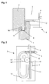
- a drive 3 is arranged, which is an actuating element 4, which as a chain or as a flexible element, for example as a flat band or as a rope with a stiffened initial area formed can be.
- the actuating element 4 acts with a wing 1 arranged Console 5 and a driver 7 together, which with a connecting element 9 is fixed to the displacement element 8.
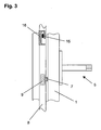
- the drive 3 has a rack 10, which with one of the rack 10 arranged toothing 11 in a pinion 14 "engages a plurality of pinions 14 may be present, which together with the teeth 11 a Forming the transmission.
- the rack 10 is moved, wherein the toothing 11 with the pinion 14 "and the actuating element 4 with the pinion 14 'is engaged, as shown in Figure 2.
- the slidably disposed in the guide 13 actuator 4 is thereby, depending on the direction of actuation of the rack 10, from the drive housing pushed out or pulled into this.
- the rack 10 can be arranged by an electric motor arranged in the drive 3 be operated. Also possible is an operation via a hand lever, a Hand crank or an external drive unit, for example a spindle drive, which operates the rack 10 via a push rod 6.
- the driver 7 acts with a sliding element 8 arranged on the wing 1 together, which has one or more bars 15, which engages with arranged on the frame 2 bolt receivers 16 pass, causing the wing 1 is locked.
- driver 7 is designed as a bolt and with a arranged on wing 1 Rieglability 16 cooperates to its locking.
- the rack 10 is moved back, the Pinion 14 "at the beginning of the opening process first over the untoothed area 12 slides, whereby the pinion 14 "and the actuator 4 first not to be moved.
- the driver 7 and the displacement element 8 is moved back, whereby the latch 15 disengage from the latch receptacles 16. If the pinion 14 "then comes back into engagement with the teeth 11, the actuator 4 by the pinion 14 'from the drive housing pushed out and the wing 1 pivoted in the direction of its open position.
Landscapes
- Engineering & Computer Science (AREA)
- Mechanical Engineering (AREA)
- Lock And Its Accessories (AREA)
- Window Of Vehicle (AREA)
- Power-Operated Mechanisms For Wings (AREA)
- Specific Sealing Or Ventilating Devices For Doors And Windows (AREA)
Abstract
Description
- Fig. 1
- eine Seitenansicht auf einen Flügel mit einem Antrieb und mit einer Verriegelungseinrichtung im Teilschnitt;
- Fig. 2
- den Antrieb nach Fig. 1 in der Draufsicht auf die Führung des Betätigungselements;
- Fig. 3
- eine Draufsicht auf eine am Flügel angeordnete Riegeleinrichtung in verriegeltem Zustand.
- 1
- Flügel
- 2
- Rahmen
- 3
- Antrieb
- 4
- Betätigungselement
- 5
- Konsole
- 6
- Schubstange
- 7
- Mitnehmer
- 8
- Schiebeelement
- 9
- Verbindungselement
- 10
- Zahnstange
- 11
- Verzahnung
- 12
- unverzahnter Bereich
- 13
- Führung
- 14
- Ritzel
- 15
- Riegel
- 16
- Riegelaufnahme
Claims (7)
- Verriegelung für einen Flügel eines Fensters oder einer Klappe, mit einem Antrieb, mit einer Zahnstange und mit einem durch die Zahnstange bewegbaren Betätigungselement zum Verschwenken des Flügels zwischen einer geschlossenen und einer geöffneten Stellung,
dadurch gekennzeichnet, dass die Zahnstange (10) mit einem Mitnehmer (7) zur Verriegelung des Flügels (1) zusammenwirkt. - Verriegelung nach Anspruch 1,
dadurch gekennzeichnet, dass die Verriegelung des Flügels durch den Mitnehmer (7) nach bzw. vor dem Antreiben des Betätigungselements (4) durch die Zahnstange (10) erfolgt. - Verriegelung nach Anspruch 1,
dadurch gekennzeichnet, dass der Mitnehmer (7) an der Zahnstange (10) festgelegt ist. - Verriegelung nach Anspruch 1,
dadurch gekennzeichnet, dass der Mitnehmer (7) nach bzw. vor dem Antreiben des Betätigungselements (4) durch die Zahnstange (10) in Formschluss mit der Zahnstange (10) gelangt. - Verriegelung nach Anspruch 1,
dadurch gekennzeichnet, dass der Mitnehmer (7) zum Eingriff in den Falzbereich zwischen Flügel (1) und Rahmen (2) ausgebildet ist. - Verriegelung nach Anspruch 1,
dadurch gekennzeichnet, dass der Mitnehmer (7) mit einem am Flügel (1) angeordneten, verschiebbar geführten Schiebeelement (8) zusammenwirkt, wobei das Schiebeelement (8) mindestens einen Riegel (15) aufweist, welcher in eine am Rahmen (2) angeordnete Riegelaufnahme (16) eingreift. - Verriegelung nach Anspruch 1,
dadurch gekennzeichnet, dass der Mitnehmer (7) als Riegel ausgebildet ist und in eine am Flügel (1) angeordnete Riegelaufnahme (16) eingreift.
Priority Applications (1)
| Application Number | Priority Date | Filing Date | Title |
|---|---|---|---|
| SI200430825T SI1493891T1 (sl) | 2003-06-30 | 2004-03-16 | Zaporna naprava za okno ali loputo |
Applications Claiming Priority (2)
| Application Number | Priority Date | Filing Date | Title |
|---|---|---|---|
| DE10329555A DE10329555A1 (de) | 2003-06-30 | 2003-06-30 | Verriegelung für einen Flügel eines Fensters oder einer Klappe |
| DE10329555 | 2003-06-30 |
Publications (2)
| Publication Number | Publication Date |
|---|---|
| EP1493891A1 true EP1493891A1 (de) | 2005-01-05 |
| EP1493891B1 EP1493891B1 (de) | 2008-06-25 |
Family
ID=33426802
Family Applications (1)
| Application Number | Title | Priority Date | Filing Date |
|---|---|---|---|
| EP04006164A Expired - Lifetime EP1493891B1 (de) | 2003-06-30 | 2004-03-16 | Verriegelung für einen Flügel eines Fensters oder einer Klappe |
Country Status (5)
| Country | Link |
|---|---|
| EP (1) | EP1493891B1 (de) |
| AT (1) | ATE399242T1 (de) |
| DE (2) | DE10329555A1 (de) |
| DK (1) | DK1493891T3 (de) |
| SI (1) | SI1493891T1 (de) |
Cited By (2)
| Publication number | Priority date | Publication date | Assignee | Title |
|---|---|---|---|---|
| EP1764469A1 (de) * | 2005-09-16 | 2007-03-21 | GSG INTERNATIONAL S.p.A. | Motorisch angetriebene Fenstereinheit mit schwenkbarer Öffnung |
| NL1031542C2 (nl) * | 2006-04-07 | 2007-10-09 | Stenman Holland Nv | Samenstel van een paneel en een kozijn, in het bijzonder een verzwenkbaar bovenlichtraam en een respectief kozijn van een gebouw. |
Citations (3)
| Publication number | Priority date | Publication date | Assignee | Title |
|---|---|---|---|---|
| EP0789126A1 (de) * | 1996-02-12 | 1997-08-13 | V. Kann Rasmussen Industri A/S | Fenster mit ein Treibstangenschloss und ein Auftriebsvorrichtung |
| EP1057959A2 (de) * | 1999-05-31 | 2000-12-06 | RBS Beschläge GmbH | Ausstellvorrichtung für Fensterflügel oder Lüftungsklappen |
| DE20022746U1 (de) * | 2000-12-22 | 2002-02-28 | esco Metallbaubeschlag-Handel Gesellschaft mbH, 71254 Ditzingen | Öffnungsvorrichtung zum Öffnen eines Oberlicht-Fensterflügels |
-
2003
- 2003-06-30 DE DE10329555A patent/DE10329555A1/de not_active Withdrawn
-
2004
- 2004-03-16 AT AT04006164T patent/ATE399242T1/de active
- 2004-03-16 SI SI200430825T patent/SI1493891T1/sl unknown
- 2004-03-16 DK DK04006164T patent/DK1493891T3/da active
- 2004-03-16 DE DE502004007420T patent/DE502004007420D1/de not_active Expired - Lifetime
- 2004-03-16 EP EP04006164A patent/EP1493891B1/de not_active Expired - Lifetime
Patent Citations (3)
| Publication number | Priority date | Publication date | Assignee | Title |
|---|---|---|---|---|
| EP0789126A1 (de) * | 1996-02-12 | 1997-08-13 | V. Kann Rasmussen Industri A/S | Fenster mit ein Treibstangenschloss und ein Auftriebsvorrichtung |
| EP1057959A2 (de) * | 1999-05-31 | 2000-12-06 | RBS Beschläge GmbH | Ausstellvorrichtung für Fensterflügel oder Lüftungsklappen |
| DE20022746U1 (de) * | 2000-12-22 | 2002-02-28 | esco Metallbaubeschlag-Handel Gesellschaft mbH, 71254 Ditzingen | Öffnungsvorrichtung zum Öffnen eines Oberlicht-Fensterflügels |
Cited By (2)
| Publication number | Priority date | Publication date | Assignee | Title |
|---|---|---|---|---|
| EP1764469A1 (de) * | 2005-09-16 | 2007-03-21 | GSG INTERNATIONAL S.p.A. | Motorisch angetriebene Fenstereinheit mit schwenkbarer Öffnung |
| NL1031542C2 (nl) * | 2006-04-07 | 2007-10-09 | Stenman Holland Nv | Samenstel van een paneel en een kozijn, in het bijzonder een verzwenkbaar bovenlichtraam en een respectief kozijn van een gebouw. |
Also Published As
| Publication number | Publication date |
|---|---|
| EP1493891B1 (de) | 2008-06-25 |
| DE502004007420D1 (de) | 2008-08-07 |
| SI1493891T1 (sl) | 2008-10-31 |
| DE10329555A1 (de) | 2005-01-27 |
| DK1493891T3 (da) | 2008-10-27 |
| ATE399242T1 (de) | 2008-07-15 |
Similar Documents
| Publication | Publication Date | Title |
|---|---|---|
| DE102017124282A1 (de) | Aufstellvorrichtung für eine Kraftfahrzeugtür | |
| DE102014119382A1 (de) | Kraftfahrzeugschlossanordnung | |
| DE4437250A1 (de) | Einrichtung für die Ausführung des Schließ- und Öffnungsvorganges eines Kippfensters | |
| DE102006059568A1 (de) | Schließanlage für Türen, Fenster oder dergleichen, insbesondere Treibstangenschloss mit Panikfunktion und Mehrpunktverriegelung | |
| EP2428380B1 (de) | Verschlusseinrichtung | |
| DE19933371A1 (de) | Schließeinrichtung mit Zuziehhilfe | |
| DE102015107955A1 (de) | Elektrische Antriebseinheit | |
| EP3994324B1 (de) | Kraftfahrzeug-türschloss | |
| EP1801332A2 (de) | Kraftfahrzeugschloss | |
| EP3401475A1 (de) | Beschlaganordnung | |
| EP2146032B1 (de) | Vorrichtung zum Öffnen und/oder Schliessen sowie zum Verriegeln eines geschlossenen Zustandes einer Verschlusseinrichtung zum Verschliessen einer Raumöffnung sowie Verschlusseinrichtung mit einer solchen Vorrichtung | |
| EP2428381B1 (de) | Verschlusseinrichtung | |
| DE102017117490A1 (de) | Kraftfahrzeugschloss | |
| EP0600228B1 (de) | Vorrichtung zum Öffnen und Schliessen eines Lukendeckels an einem Kampffahrzeug, insbesondere einem Kampfpanzer | |
| DE3824729A1 (de) | Antriebsvorrichtung, insbesondere fuer schiebedaecher, schiebe-hebedaecher, fensterscheiben o.dgl. | |
| EP2428379B1 (de) | Verschlusseinrichtung | |
| EP1243728B1 (de) | Antriebseinheit für Fenster oder Türen | |
| EP1493891B1 (de) | Verriegelung für einen Flügel eines Fensters oder einer Klappe | |
| DE102020132139A1 (de) | Zuzieheinrichtung für ein Kraftfahrzeug-Schloss | |
| WO2023006144A1 (de) | Aufstellvorrichtung für eine kraftfahrzeug-tür | |
| EP1493892B1 (de) | Verriegelung für den Flügel eines Fensters oder einer Klappe | |
| DE202012104527U1 (de) | Beschlag für Fenster, Türen oder dergleichen | |
| EP1288418B1 (de) | Beschlagseinheit für ein Kipp- oder Drehkippfenster | |
| EP1344883B1 (de) | Verriegelungseinrichtung für eine Tür | |
| DE202006011218U1 (de) | Notfallentriegelung |
Legal Events
| Date | Code | Title | Description |
|---|---|---|---|
| PUAI | Public reference made under article 153(3) epc to a published international application that has entered the european phase |
Free format text: ORIGINAL CODE: 0009012 |
|
| AK | Designated contracting states |
Kind code of ref document: A1 Designated state(s): AT BE BG CH CY CZ DE DK EE ES FI FR GB GR HU IE IT LI LU MC NL PL PT RO SE SI SK TR |
|
| AX | Request for extension of the european patent |
Extension state: AL LT LV MK |
|
| 17P | Request for examination filed |
Effective date: 20050701 |
|
| AKX | Designation fees paid |
Designated state(s): AT BE BG CH CY CZ DE DK EE ES FI FR GB GR HU IE IT LI LU MC NL PL PT RO SE SI SK TR |
|
| 17Q | First examination report despatched |
Effective date: 20050811 |
|
| GRAP | Despatch of communication of intention to grant a patent |
Free format text: ORIGINAL CODE: EPIDOSNIGR1 |
|
| GRAS | Grant fee paid |
Free format text: ORIGINAL CODE: EPIDOSNIGR3 |
|
| GRAA | (expected) grant |
Free format text: ORIGINAL CODE: 0009210 |
|
| AK | Designated contracting states |
Kind code of ref document: B1 Designated state(s): AT BE BG CH CY CZ DE DK EE ES FI FR GB GR HU IE IT LI LU MC NL PL PT RO SE SI SK TR |
|
| REG | Reference to a national code |
Ref country code: GB Ref legal event code: FG4D Free format text: NOT ENGLISH |
|
| REG | Reference to a national code |
Ref country code: CH Ref legal event code: EP Ref country code: CH Ref legal event code: NV |
|
| REF | Corresponds to: |
Ref document number: 502004007420 Country of ref document: DE Date of ref document: 20080807 Kind code of ref document: P |
|
| REG | Reference to a national code |
Ref country code: IE Ref legal event code: FG4D Free format text: LANGUAGE OF EP DOCUMENT: GERMAN |
|
| REG | Reference to a national code |
Ref country code: RO Ref legal event code: EPE |
|
| REG | Reference to a national code |
Ref country code: SE Ref legal event code: TRGR |
|
| PG25 | Lapsed in a contracting state [announced via postgrant information from national office to epo] |
Ref country code: NL Free format text: LAPSE BECAUSE OF FAILURE TO SUBMIT A TRANSLATION OF THE DESCRIPTION OR TO PAY THE FEE WITHIN THE PRESCRIBED TIME-LIMIT Effective date: 20080625 Ref country code: PL Free format text: LAPSE BECAUSE OF FAILURE TO SUBMIT A TRANSLATION OF THE DESCRIPTION OR TO PAY THE FEE WITHIN THE PRESCRIBED TIME-LIMIT Effective date: 20080625 |
|
| NLV1 | Nl: lapsed or annulled due to failure to fulfill the requirements of art. 29p and 29m of the patents act | ||
| PG25 | Lapsed in a contracting state [announced via postgrant information from national office to epo] |
Ref country code: CZ Free format text: LAPSE BECAUSE OF FAILURE TO SUBMIT A TRANSLATION OF THE DESCRIPTION OR TO PAY THE FEE WITHIN THE PRESCRIBED TIME-LIMIT Effective date: 20080625 Ref country code: ES Free format text: LAPSE BECAUSE OF FAILURE TO SUBMIT A TRANSLATION OF THE DESCRIPTION OR TO PAY THE FEE WITHIN THE PRESCRIBED TIME-LIMIT Effective date: 20081006 Ref country code: PT Free format text: LAPSE BECAUSE OF FAILURE TO SUBMIT A TRANSLATION OF THE DESCRIPTION OR TO PAY THE FEE WITHIN THE PRESCRIBED TIME-LIMIT Effective date: 20081125 |
|
| REG | Reference to a national code |
Ref country code: IE Ref legal event code: FD4D |
|
| PG25 | Lapsed in a contracting state [announced via postgrant information from national office to epo] |
Ref country code: SK Free format text: LAPSE BECAUSE OF FAILURE TO SUBMIT A TRANSLATION OF THE DESCRIPTION OR TO PAY THE FEE WITHIN THE PRESCRIBED TIME-LIMIT Effective date: 20080625 |
|
| PG25 | Lapsed in a contracting state [announced via postgrant information from national office to epo] |
Ref country code: IE Free format text: LAPSE BECAUSE OF FAILURE TO SUBMIT A TRANSLATION OF THE DESCRIPTION OR TO PAY THE FEE WITHIN THE PRESCRIBED TIME-LIMIT Effective date: 20080625 Ref country code: EE Free format text: LAPSE BECAUSE OF FAILURE TO SUBMIT A TRANSLATION OF THE DESCRIPTION OR TO PAY THE FEE WITHIN THE PRESCRIBED TIME-LIMIT Effective date: 20080625 Ref country code: BG Free format text: LAPSE BECAUSE OF FAILURE TO SUBMIT A TRANSLATION OF THE DESCRIPTION OR TO PAY THE FEE WITHIN THE PRESCRIBED TIME-LIMIT Effective date: 20080925 |
|
| PLBE | No opposition filed within time limit |
Free format text: ORIGINAL CODE: 0009261 |
|
| STAA | Information on the status of an ep patent application or granted ep patent |
Free format text: STATUS: NO OPPOSITION FILED WITHIN TIME LIMIT |
|
| 26N | No opposition filed |
Effective date: 20090326 |
|
| BERE | Be: lapsed |
Owner name: GEZE G.M.B.H. Effective date: 20090331 |
|
| PG25 | Lapsed in a contracting state [announced via postgrant information from national office to epo] |
Ref country code: MC Free format text: LAPSE BECAUSE OF NON-PAYMENT OF DUE FEES Effective date: 20090331 |
|
| GBPC | Gb: european patent ceased through non-payment of renewal fee |
Effective date: 20090316 |
|
| PG25 | Lapsed in a contracting state [announced via postgrant information from national office to epo] |
Ref country code: BE Free format text: LAPSE BECAUSE OF NON-PAYMENT OF DUE FEES Effective date: 20090331 |
|
| PG25 | Lapsed in a contracting state [announced via postgrant information from national office to epo] |
Ref country code: GB Free format text: LAPSE BECAUSE OF NON-PAYMENT OF DUE FEES Effective date: 20090316 |
|
| PG25 | Lapsed in a contracting state [announced via postgrant information from national office to epo] |
Ref country code: GR Free format text: LAPSE BECAUSE OF FAILURE TO SUBMIT A TRANSLATION OF THE DESCRIPTION OR TO PAY THE FEE WITHIN THE PRESCRIBED TIME-LIMIT Effective date: 20080926 |
|
| PG25 | Lapsed in a contracting state [announced via postgrant information from national office to epo] |
Ref country code: LU Free format text: LAPSE BECAUSE OF NON-PAYMENT OF DUE FEES Effective date: 20090316 |
|
| PG25 | Lapsed in a contracting state [announced via postgrant information from national office to epo] |
Ref country code: HU Free format text: LAPSE BECAUSE OF FAILURE TO SUBMIT A TRANSLATION OF THE DESCRIPTION OR TO PAY THE FEE WITHIN THE PRESCRIBED TIME-LIMIT Effective date: 20081226 |
|
| PG25 | Lapsed in a contracting state [announced via postgrant information from national office to epo] |
Ref country code: CY Free format text: LAPSE BECAUSE OF FAILURE TO SUBMIT A TRANSLATION OF THE DESCRIPTION OR TO PAY THE FEE WITHIN THE PRESCRIBED TIME-LIMIT Effective date: 20080625 |
|
| REG | Reference to a national code |
Ref country code: FR Ref legal event code: PLFP Year of fee payment: 13 |
|
| REG | Reference to a national code |
Ref country code: FR Ref legal event code: PLFP Year of fee payment: 14 |
|
| REG | Reference to a national code |
Ref country code: FR Ref legal event code: PLFP Year of fee payment: 15 |
|
| PGFP | Annual fee paid to national office [announced via postgrant information from national office to epo] |
Ref country code: FI Payment date: 20180322 Year of fee payment: 15 Ref country code: DK Payment date: 20180321 Year of fee payment: 15 |
|
| PGFP | Annual fee paid to national office [announced via postgrant information from national office to epo] |
Ref country code: TR Payment date: 20180315 Year of fee payment: 15 |
|
| REG | Reference to a national code |
Ref country code: DK Ref legal event code: EBP Effective date: 20190331 |
|
| PG25 | Lapsed in a contracting state [announced via postgrant information from national office to epo] |
Ref country code: FI Free format text: LAPSE BECAUSE OF NON-PAYMENT OF DUE FEES Effective date: 20190316 |
|
| PG25 | Lapsed in a contracting state [announced via postgrant information from national office to epo] |
Ref country code: DK Free format text: LAPSE BECAUSE OF NON-PAYMENT OF DUE FEES Effective date: 20190331 |
|
| PGFP | Annual fee paid to national office [announced via postgrant information from national office to epo] |
Ref country code: AT Payment date: 20200320 Year of fee payment: 17 Ref country code: RO Payment date: 20200225 Year of fee payment: 17 Ref country code: SE Payment date: 20200323 Year of fee payment: 17 |
|
| PGFP | Annual fee paid to national office [announced via postgrant information from national office to epo] |
Ref country code: CH Payment date: 20200319 Year of fee payment: 17 Ref country code: SI Payment date: 20200221 Year of fee payment: 17 |
|
| PGFP | Annual fee paid to national office [announced via postgrant information from national office to epo] |
Ref country code: FR Payment date: 20200319 Year of fee payment: 17 |
|
| PGFP | Annual fee paid to national office [announced via postgrant information from national office to epo] |
Ref country code: DE Payment date: 20200331 Year of fee payment: 17 |
|
| PGFP | Annual fee paid to national office [announced via postgrant information from national office to epo] |
Ref country code: IT Payment date: 20200318 Year of fee payment: 17 |
|
| REG | Reference to a national code |
Ref country code: DE Ref legal event code: R231 Ref document number: 502004007420 Country of ref document: DE |
|
| PG25 | Lapsed in a contracting state [announced via postgrant information from national office to epo] |
Ref country code: DE Free format text: LAPSE BECAUSE OF THE APPLICANT RENOUNCES Effective date: 20210209 |
|
| REG | Reference to a national code |
Ref country code: CH Ref legal event code: PL |
|
| REG | Reference to a national code |
Ref country code: AT Ref legal event code: MM01 Ref document number: 399242 Country of ref document: AT Kind code of ref document: T Effective date: 20210316 |
|
| PG25 | Lapsed in a contracting state [announced via postgrant information from national office to epo] |
Ref country code: RO Free format text: LAPSE BECAUSE OF NON-PAYMENT OF DUE FEES Effective date: 20210316 |
|
| PG25 | Lapsed in a contracting state [announced via postgrant information from national office to epo] |
Ref country code: AT Free format text: LAPSE BECAUSE OF NON-PAYMENT OF DUE FEES Effective date: 20210316 Ref country code: CH Free format text: LAPSE BECAUSE OF NON-PAYMENT OF DUE FEES Effective date: 20210331 Ref country code: LI Free format text: LAPSE BECAUSE OF NON-PAYMENT OF DUE FEES Effective date: 20210331 Ref country code: SE Free format text: LAPSE BECAUSE OF NON-PAYMENT OF DUE FEES Effective date: 20210317 Ref country code: FR Free format text: LAPSE BECAUSE OF NON-PAYMENT OF DUE FEES Effective date: 20210331 |
|
| REG | Reference to a national code |
Ref country code: SI Ref legal event code: KO00 Effective date: 20211201 |
|
| PG25 | Lapsed in a contracting state [announced via postgrant information from national office to epo] |
Ref country code: SI Free format text: LAPSE BECAUSE OF NON-PAYMENT OF DUE FEES Effective date: 20210317 |
|
| PG25 | Lapsed in a contracting state [announced via postgrant information from national office to epo] |
Ref country code: IT Free format text: LAPSE BECAUSE OF NON-PAYMENT OF DUE FEES Effective date: 20210316 |
|
| PG25 | Lapsed in a contracting state [announced via postgrant information from national office to epo] |
Ref country code: TR Free format text: LAPSE BECAUSE OF NON-PAYMENT OF DUE FEES Effective date: 20190316 |
|
| P01 | Opt-out of the competence of the unified patent court (upc) registered |
Effective date: 20230510 |