EP1493461A2 - Stirnstütze für eine Atemmaske - Google Patents
Stirnstütze für eine Atemmaske Download PDFInfo
- Publication number
- EP1493461A2 EP1493461A2 EP04022930A EP04022930A EP1493461A2 EP 1493461 A2 EP1493461 A2 EP 1493461A2 EP 04022930 A EP04022930 A EP 04022930A EP 04022930 A EP04022930 A EP 04022930A EP 1493461 A2 EP1493461 A2 EP 1493461A2
- Authority
- EP
- European Patent Office
- Prior art keywords
- support
- forehead
- support element
- longitudinal axis
- pad
- Prior art date
- Legal status (The legal status is an assumption and is not a legal conclusion. Google has not performed a legal analysis and makes no representation as to the accuracy of the status listed.)
- Granted
Links
Images


Classifications
-
- A—HUMAN NECESSITIES
- A61—MEDICAL OR VETERINARY SCIENCE; HYGIENE
- A61M—DEVICES FOR INTRODUCING MEDIA INTO, OR ONTO, THE BODY; DEVICES FOR TRANSDUCING BODY MEDIA OR FOR TAKING MEDIA FROM THE BODY; DEVICES FOR PRODUCING OR ENDING SLEEP OR STUPOR
- A61M16/00—Devices for influencing the respiratory system of patients by gas treatment, e.g. mouth-to-mouth respiration; Tracheal tubes
- A61M16/06—Respiratory or anaesthetic masks
- A61M16/0605—Means for improving the adaptation of the mask to the patient
- A61M16/0633—Means for improving the adaptation of the mask to the patient with forehead support
- A61M16/0638—Means for improving the adaptation of the mask to the patient with forehead support in the form of a pivot
-
- A—HUMAN NECESSITIES
- A61—MEDICAL OR VETERINARY SCIENCE; HYGIENE
- A61M—DEVICES FOR INTRODUCING MEDIA INTO, OR ONTO, THE BODY; DEVICES FOR TRANSDUCING BODY MEDIA OR FOR TAKING MEDIA FROM THE BODY; DEVICES FOR PRODUCING OR ENDING SLEEP OR STUPOR
- A61M16/00—Devices for influencing the respiratory system of patients by gas treatment, e.g. mouth-to-mouth respiration; Tracheal tubes
- A61M16/06—Respiratory or anaesthetic masks
- A61M16/0605—Means for improving the adaptation of the mask to the patient
- A61M16/0633—Means for improving the adaptation of the mask to the patient with forehead support
- A61M16/0644—Means for improving the adaptation of the mask to the patient with forehead support having the means for adjusting its position
- A61M16/0655—Means for improving the adaptation of the mask to the patient with forehead support having the means for adjusting its position in the form of a linear or curvilinear slide
Definitions
- the invention relates to a device for supporting a Respiratory mask in the area of a forehead of a patient who at least one in the region of at least one support leg the breathing mask arranged and an adjusting device a support member connected to the support leg having.
- Such support elements with adjusting serve to one to a respective facial geometry of the patient adapted support of a breathing mask in the region of a forehead of the patient.
- the known forehead supports point either an adjustment to an adjustment to make substantially perpendicular to the forehead and thereby changing the effective frontal distance, or around an adjustment substantially parallel to the facial surface make an adjustment to the respective Forehead height perform.
- Mechanical Adjustments or the targeted installation of elements with a relative to each other different suitable Dimensioning are known for this purpose.
- a forehead support with an adjustment for specification an effective frontal distance is for example in the US-PS 61 19 693 described. It becomes a bridge-like one here Forehead support disclosed, which has two support arms with the Respiratory mask is connected.
- a cross member of the support element which carries two forehead pads, points in the area of his Low support facing extension detents.
- the hitherto known devices can with regard to their ease of adjustment and their usability not all Meet requirements resulting from use by result in the patient himself.
- Object of the present invention is therefore an apparatus of the type mentioned in the opening paragraph, that a versatile adjustability at the same time simple operation is provided.
- the Forehead pad is formed as an elastomeric band, the is positioned by a fork-like holder.
- a detent is provided for the guidance of the adjusting device in the direction of the longitudinal axis .
- a further ease of operation can be achieved be that for the adjustment of the support element transversely to Longitudinal axis a detent is provided.
- a soft padding of the forehead can be done by that the support element carries a forehead pad, as a Gelkissen is formed.
- the support element a Forehead pad wearing, which is designed as an elastomeric pad is.
- the support element is a forehead pad carries, which is designed as a foam pad.
- a further increase of the adjustment flexibility can thereby be achieved, that the support element relative to Holding leg is arranged pivotably.
- frontal pad in frontal Direction is arranged tilted.
- a further increased ease of use can be achieved be that the forehead pad tiltably arranged laterally is.
- a particularly good adaptation to a front contour is characterized assists that the forehead pad as an elastomeric Band is formed by a fork-like bracket is positioned.
- the forehead pad is formed as an elastomeric band which is constructed in one piece with a fork-like mount is.
- Fig. 1 shows a perspective view of a breathing mask (1), which consists essentially of a mask body (2) made of a solid material and a mask cushion (3) made of a soft material.
- the mask cushion (3) can on a pad base (4) on an edge of the mask body (2) be plugged.
- the mask cushion (3) limited with sealing lips (5) a breathing opening (6), in when used by a patient, a nose of the Patients is introduced.
- a support leg (7) is attached, with a longitudinal axis (8) substantially parallel to one of the breathing opening (6) spanned Plane extends.
- the support leg (7) has a mounting opening (9) into which an adjusting device (10) is used.
- the adjusting device (10) has transversely to Longitudinal axis (8) has a guide recess (11) into which a Shank (12) of a support element (13) is inserted.
- the Support element (13) carries a forehead pad (14).
- the Forehead pad (14) substantially transverse to the longitudinal axis (8) extends.
- the mounting hole (9) is formed similar to a longitudinal slot, the extends in the direction of the longitudinal axis (8).
- Fig. 2 illustrates also that on the mask body (2) laterally two flanges (16) are formed, each with slit-shaped Recesses (17) are provided.
- adjusting device (10) with a base body (21) through the mounting opening (9) protrudes and with a plate (22) on the support leg (7).
- the main body (21) has resilient mounted clamping webs (23) on the shaft (12) of the Support element (13) within the guide recess (11) fix the adjusting device (10).
- FIG. 4 illustrates that the shank (12) in the region of its clamping webs (23) facing sides with a detent (24) is provided to Here, too, a defined and gradual positioning to allow the support element (13).
- Fig. 4 also illustrates that the support leg (7) essentially of a leg plate (25) as well Support webs (26), which is substantially perpendicular to Leg plate (25) are arranged and raised to an Flexural rigidity contribute. Rejuvenate the support webs (26) in a direction away from the mask body (2) and are in the area of their thickened ends on the mask body (2) molded.
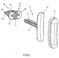
- Fig. 5 illustrates in an exploded view the Construction of the adjusting device (10) and the support element (13).
- the support element (13) has a support plate (27) onto which the Forehead pad (14) is attached.
- the clamping webs (23) with locking projections (28) are provided, which engage in the detents (24) can.
- the clamping webs (23) are the locking projections (28) from the Latch (24) led out.
- Fig. 6 illustrates that the forehead pad (14) in the area an edge (30) provided with a U-profile (31) is that attachable to an edge (32) of the support plate (27) is.
- the forehead pad (14) provides for deployment a sufficient intrinsic stability inner Cross webs (33), which in an embodiment of the forehead pad (14) made of an elastomeric material to a good one Compromise between a sufficient dimensional stability and contribute to sufficient flexibility.
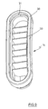
- FIG. 7 The illustration of the support element (13) in FIG. 7 illustrates that by the detent (24) a plurality of Grid compartments are trained, each for recording the locking projections (28) of the clamping webs (23) are provided are. It can also be seen that the support plate (27) slightly curved to adapt to the contour of a to ensure human forehead.
- the Forehead pad (14) has a hood-like cross-sectional design on and off the crossbars (33) are both Long sides of the forehead pad (14) supported relative to each other as well as a stiffening in the area of one the edge (30) turned away final rounding.
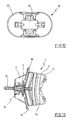
- FIG. 10 shows the adjusting device (10) in greater detail. It can be seen that the base body (21) in essentially consists of two plates (34, 35), between where the clamping webs (23) are arranged.
- Fig. 12 illustrates the combination of the adjusting device (10) with the shaft (12).
- Fig. 13 shows in a another side view as an assembly diagram of the combination the breathing mask (1) with a forehead pad (14), the via a shaft (12) of an adjusting device (10) is fixed in the region of the support leg (7).
- FIGS. 14 and 15 again show the structure of the adjusting device (10). Further illustrations of the adjustment (10) can also be found in Fig. 16 and in Fig. 17.
- Fig. 18 shows in a further perspective view again the support element (13), in particular recognizable in that the shaft (12) is similar to a cross-sectional profile to an I has.
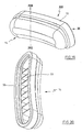
- Fig. 19 and Fig. 20 show again in further perspective views the design the forehead pad (14).
- Fig. 21 illustrates that the forehead pad (14) substantially a symmetrical design to its longitudinal axis having.
- Fig. 22 illustrates the rounded outer Contouring of the forehead cushion (14).
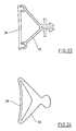
- Fig. 23 shows a modified embodiment in which an elastomeric band (38) from a fork-like mount (39) is positioned.
- the elastomeric band (38) may become Adjust the contour of the forehead and the inclination of the forehead.
- FIG. 24 shows an embodiment modified from FIG. 23, FIG. in which the elastomeric band (38) and the holder (39) are made in one piece.
- a material e.g. Foam or a hollow body can be used.
- a typical adjustment procedure is such that the patient first the breathing mask (1) positioned in the area of his nose and in a first step, an adaptation to the Forehead height by a displacement of the adjustment (10) within the mounting opening (9) in the direction of Longitudinal axis (8) performs.
- About the detent (15) is a supported defined positioning.
- After a suitable Arrangement and locking of the adjusting device (10) within the mounting hole (9) is an adaptation to the Front distance by pulling out of the shaft (12) the guide recess (11) or by a pushing of the shaft (12) in the guide recess (11) performed.
Abstract
Description
- Fig. 1
- Eine perspektivische Darstellung einer Atemmaske mit einem Stützelement, das sowohl in Richtung einer Längsachse eines Halterungsschenkels als auch quer zur Längsachse positionierbar ist,
- Fig. 2
- eine Ansicht gemäß Blickrichtung II in Fig. 1,
- Fig. 3
- eine Ansicht gemäß Blickrichtung III in Fig. 1,
- Fig. 4
- eine perspektivische Darstellung gemäß Blickrichtung IV in Fig. 3,
- Fig. 5
- eine Explosionsdarstellung des Stützelementes mit Stirnpolster und Verstelleinrichtung,
- Fig. 6
- eine Darstellung der Anordnung gemäß Blickrichtung VI in Fig. 5,
- Fig. 7
- eine vergrößerte perspektivische Darstellung des Stützelementes,
- Fig. 8
- eine Seitenansicht des Stützelementes gemäß Blickrichtung VIII in Fig. 7,
- Fig. 9
- eine vergrößerte perspektivische Darstellung des Stirnpolsters,
- Fig. 10
- eine vergrößerte perspektivische Darstellung der Verstelleinrichtung,
- Fig. 11
- eine Darstellung der Verstelleinrichtung gemäß Blickrichtung XI in Fig. 10,
- Fig. 12
- die Verstellvorrichtung gemäß Blickrichtung XII in Fig. 10,
- Fig. 13
- eine Seitenansicht gemäß Blickrichtung XIII in Fig. 1,
- Fig. 14
- eine weitere perspektivische Darstellung der Verstelleinrichtung,
- Fig. 15
- einen Längsschnitt gemäß Schnittlinie XV-XV in Fig. 11 nach einer Drehung um 90°,
- Fig. 16
- eine perspektivische Darstellung der Verstelleinrichtung gemäß Blickrichtung XVI in Fig. 14,
- Fig. 17
- eine weitere perspektivische Darstellung der Verstelleinrichtung,
- Fig. 18
- eine weitere perspektivische Darstellung des Stützelementes,
- Fig. 19
- eine weitere perspektivische Darstellung des Stirnpolsters,
- Fig. 20
- eine perspektivische Darstellung gemäß Blickrichtung XX in Fig. 19 nach einer Drehung um 90°,
- Fig. 21
- eine Ansicht gemäß Blickrichtung XXI in Fig. 19,
- Fig. 22
- einen Querschnitt gemäß Schnittlinie XXII-XXII in Fig. 19,
- Fig. 23
- eine Prinzipdarstellung einer brückenartigen Stirnstütze und
- Fig. 24
- eine gegenüber Fig. 23 abgewandelte Konstruktion einer brückenförmigen Stirnstütze in einteiliger Ausführung.
Claims (16)
- Vorrichtung zur Abstützung einer Atemmaske im Bereich einer Stirn eines Patienten, die mindestens ein im Bereich mindestens eines Halterungsschenkels der Atemmaske angeordnetes und über eine Verstelleinrichtung mit dem Halterungsschenkel verbundenes Stützelement aufweist, dadurch gekennzeichnet, daß das Stirnpolster (14) als ein elastomeres Band (38) ausgebildet ist, das von einer gabelartigen Halterung (39) positioniert ist.
- Vorrichtung nach Anspruch 1, dadurch gekennzeichnet, daß für die Verstelleinrichtung (10) eine Arretierung in Richtung der Längsachse (8) vorgesehen ist.
- Vorrichtung nach Anspruch 1 oder 2, dadurch gekennzeichnet, daß für das Stützelement (13) eine Arretierung quer zur Längsachse (8) vorgesehen ist.
- Vorrichtung nach einem der Ansprüche 1 bis 3, dadurch gekennzeichnet, daß für die Führung der Verstelleinrichtung (10) in Richtung der Längsachse (8) eine Rastung vorgesehen ist.
- Vorrichtung nach einem der Ansprüche 1 bis 3, dadurch gekennzeichnet, daß die Verstelleinrichtung (10) in Richtung der Längsachse (8) stufenlos verstellbar ist.
- Vorrichtung nach einem der Ansprüche 1 bis 5, dadurch gekennzeichnet, daß für die Verstellung des Stützelementes (13) quer zur Längsachse (8) eine Rastung vorgesehen ist.
- Vorrichtung nach einem der Ansprüche 1 bis 5, dadurch gekennzeichnet, daß das Stützelement (13) quer zur Längsachse (8) stufenlos verstellbar ist.
- Vorrichtung nach einem der Ansprüche 1 bis 7, dadurch gekennzeichnet, daß das Stützelement (13) ein Stirnpolster (14) trägt, das als ein Gelkissen ausgebildet ist.
- Vorrichtung nach einem der Ansprüche 1 bis 7, dadurch gekennzeichnet, daß das Stützelement (13) ein Stirnpolster (14) trägt, das als ein elastomeres Polster ausgebildet ist.
- Vorrichtung nach einem der Ansprüche 1 bis 7, dadurch gekennzeichnet, daß das Stützelement (13) ein Stirnpolster (14) trägt, das als ein Schaumpolster ausgebildet ist.
- Vorrichtung nach einem der Ansprüche 1 bis 10, dadurch gekennzeichnet, daß das Stützelement (13) relativ zum Halterungsschenkel (7) verschwenkbar angeordnet ist.
- Vorrichtung nach einem der Ansprüche 1 bis 11, dadurch gekennzeichnet, daß der Halterungsschenkel (7) relativ zu einem Maskengrundkörper (2) der Atemmaske (1) verschwenkbar angeordnet ist.
- Vorrichtung nach einem der Ansprüche 1 bis 12, dadurch gekennzeichnet, daß das Stirnpolster (13) in frontaler Richtung verkippbar angeordnet ist.
- Vorrichtung nach einem der Ansprüche 1 bis 13, dadurch gekennzeichnet, daß das Stirnpolster (14) seitlich kippbar angeordnet ist.
- Vorrichtung zur Abstützung einer Atemmaske im Bereich einer Stirn eines Patienten, die mindestens ein im Bereich mindestens eines Halterungsschenkels der Atemmaske angeordnetes und über eine Verstelleinrichtung mit dem Halterungsschenkel verbundenes Stützelement aufweist, dadurch gekennzeichnet, daß das Stirnpolster (14) als ein elastomeres Band (38) ausgebildet ist, das einteilig mit einer gabelartigen Halterung (39) konstruiert ist.
- Vorrichtung zur Abstützung einer Atemmaske im Bereich einer Stirn eines Patienten, die mindestens ein im Bereich mindestens eines Halterungsschenkels der Atemmaske angeordnetes und über eine Verstelleinrichtung mit dem Halterungsschenkel verbundenes Stützelement aufweist, dadurch gekennzeichnet, daß der Halterungsschenkel (7) relativ zu einem Maskengrundkörper (2) der Atemmaske (1) verschwenkbar angeordnet ist und daß das Stirnpolster (14) als ein elastomeres Band (38) ausgebildet ist, das von einer gabelartigen Halterung (39) in mindestens zwei unterschiedlichen Positionierungen entlang einer Längsachse (8) des Halterungsschenkels (7) arretierbar ist.
Applications Claiming Priority (3)
| Application Number | Priority Date | Filing Date | Title |
|---|---|---|---|
| DE10056331 | 2000-11-14 | ||
| DE10056331 | 2000-11-14 | ||
| EP01126897A EP1205205B1 (de) | 2000-11-14 | 2001-11-12 | Atemmaske mit Stirnstütze |
Related Parent Applications (1)
| Application Number | Title | Priority Date | Filing Date |
|---|---|---|---|
| EP01126897A Division EP1205205B1 (de) | 2000-11-14 | 2001-11-12 | Atemmaske mit Stirnstütze |
Publications (3)
| Publication Number | Publication Date |
|---|---|
| EP1493461A2 true EP1493461A2 (de) | 2005-01-05 |
| EP1493461A3 EP1493461A3 (de) | 2005-01-12 |
| EP1493461B1 EP1493461B1 (de) | 2006-10-04 |
Family
ID=7663217
Family Applications (3)
| Application Number | Title | Priority Date | Filing Date |
|---|---|---|---|
| EP01126897A Expired - Lifetime EP1205205B1 (de) | 2000-11-14 | 2001-11-12 | Atemmaske mit Stirnstütze |
| EP04022931.2A Expired - Lifetime EP1493462B1 (de) | 2000-11-14 | 2001-11-12 | Atemmaske mit Stirnstütze |
| EP04022930A Expired - Lifetime EP1493461B1 (de) | 2000-11-14 | 2001-11-12 | Atemmaske mit einer Stirnstütze |
Family Applications Before (2)
| Application Number | Title | Priority Date | Filing Date |
|---|---|---|---|
| EP01126897A Expired - Lifetime EP1205205B1 (de) | 2000-11-14 | 2001-11-12 | Atemmaske mit Stirnstütze |
| EP04022931.2A Expired - Lifetime EP1493462B1 (de) | 2000-11-14 | 2001-11-12 | Atemmaske mit Stirnstütze |
Country Status (3)
| Country | Link |
|---|---|
| EP (3) | EP1205205B1 (de) |
| AT (2) | ATE297777T1 (de) |
| DE (4) | DE10155152A1 (de) |
Cited By (4)
| Publication number | Priority date | Publication date | Assignee | Title |
|---|---|---|---|---|
| DE102005042180A1 (de) * | 2004-09-03 | 2006-05-04 | Weinmann Geräte für Medizin GmbH & Co. KG | Vorrichtung zur Beatmung |
| WO2010133218A3 (de) * | 2009-05-18 | 2011-03-17 | Weinmann Geräte für Medizin GmbH + Co. KG | Vorrichtung zur beatmung mit einer befestigungseinrichtung |
| CN101472637B (zh) * | 2006-06-16 | 2012-01-11 | 雷斯梅德有限公司 | 面罩的前额支架 |
| WO2012156845A1 (en) * | 2011-05-17 | 2012-11-22 | Koninklijke Philips Electronics N.V. | Adjustable locking forehead support for a patient interface device |
Families Citing this family (32)
| Publication number | Priority date | Publication date | Assignee | Title |
|---|---|---|---|---|
| DE20017940U1 (de) | 2000-10-19 | 2000-12-28 | Map Gmbh | Atemmaske zur Zufuhr eines Atemgases zu einem Maskenanwender sowie Ableitungseinrichtung zur Ableitung von Atemgas |
| DE10201682A1 (de) | 2002-01-17 | 2003-07-31 | Map Medizin Technologie Gmbh | Atemmaskenanordnung |
| DE50214539D1 (de) | 2001-10-22 | 2010-08-26 | Map Medizin Technologie Gmbh | Medizinische Maske |
| DE10151984C5 (de) | 2001-10-22 | 2008-07-17 | Map Medizin-Technologie Gmbh | Applikationsvorrichtung für eine Atemmaskenanordnung |
| CN103143098B (zh) | 2002-09-06 | 2016-03-09 | 瑞思迈有限公司 | 呼吸面罩的前额衬垫 |
| WO2004052438A1 (en) | 2002-12-06 | 2004-06-24 | Fisher & Paykel Healthcare Limited | Mouthpiece |
| US7503327B2 (en) | 2003-04-10 | 2009-03-17 | Resmed Limited | Mask with integral cushion and forehead piece |
| AU2004234183B2 (en) | 2003-05-02 | 2011-01-20 | Resmed Limited | A mask system |
| EP1648543B1 (de) * | 2003-07-30 | 2018-03-28 | Fisher & Paykel Healthcare Limited | Stirnauflage für atemmasken |
| DE102004002870B4 (de) | 2004-01-19 | 2017-01-19 | Löwenstein Medical Technology S.A. | Atemmaske mit Stirnstütze |
| CN106110464B (zh) * | 2004-06-16 | 2019-03-12 | 瑞思迈有限公司 | 呼吸面罩组件的软垫 |
| ES2443959T5 (es) | 2005-01-12 | 2018-04-02 | Resmed Limited | Almohadilla para interfaz con un paciente |
| EP2786775A3 (de) * | 2005-01-12 | 2014-12-17 | ResMed Ltd. | Stirnstützen für Gesichtsmasken |
| US8171934B1 (en) * | 2005-07-15 | 2012-05-08 | Ric Investments, Llc | Forehead pad and forehead support assembly |
| WO2007041751A1 (en) | 2005-10-14 | 2007-04-19 | Resmed Limited | Cushion to frame assembly mechanism |
| NZ701505A (en) | 2005-10-25 | 2016-06-24 | Resmed Ltd | Interchangeable mask assembly |
| US9387301B2 (en) | 2006-12-19 | 2016-07-12 | Koninklijke Philips N.V. | Pad assembly having outer casing and support element |
| US8517023B2 (en) | 2007-01-30 | 2013-08-27 | Resmed Limited | Mask system with interchangeable headgear connectors |
| NZ578334A (en) | 2007-04-19 | 2011-01-28 | Resmed Ltd | Mask frame connected to face cushion via intervening clip |
| US9707367B2 (en) * | 2007-06-21 | 2017-07-18 | Resmed Limited | Auto-adjusting mask stabilizer |
| US11331447B2 (en) | 2008-03-04 | 2022-05-17 | ResMed Pty Ltd | Mask system with snap-fit shroud |
| NZ765880A (en) | 2008-03-04 | 2022-04-29 | ResMed Pty Ltd | Mask system |
| CN102019022B (zh) * | 2009-09-21 | 2013-05-22 | 新广业股份有限公司 | 呼吸面罩 |
| WO2011080605A1 (en) * | 2009-12-28 | 2011-07-07 | Koninklijke Philips Electronics N.V. | Pad assembly having outer casing and support element |
| WO2012127359A1 (en) * | 2011-03-21 | 2012-09-27 | Koninklijke Philips Electronics N.V. | Helical forehead support adjustment mechanism |
| EP2601993B1 (de) * | 2011-12-07 | 2018-02-14 | Löwenstein Medical Technology S.A. | Vorrichtung zur Positionierung eines Patienteninterface |
| CN103182126B (zh) * | 2011-12-29 | 2017-04-12 | 皇家飞利浦电子股份有限公司 | 具有可调节前额支撑件的患者界面系统 |
| EP2872207B1 (de) * | 2012-07-11 | 2019-09-11 | Koninklijke Philips N.V. | Patientenschnittstelle |
| WO2014009838A1 (en) * | 2012-07-11 | 2014-01-16 | Koninklijke Philips N.V. | Patient interface |
| CN103536996B (zh) * | 2013-10-25 | 2015-10-28 | 长沙比扬医疗器械有限公司 | 一种呼吸面罩前额支撑架及具有该支撑架的呼吸面罩 |
| CN103961776B (zh) * | 2014-05-30 | 2017-03-15 | 北京怡和嘉业医疗科技有限公司 | 呼吸面罩、面罩前额支架以及面罩框架 |
| DE102019131147A1 (de) | 2018-11-30 | 2020-06-04 | Löwenstein Medical Technology S.A. | Vorrichtung zur Abstützung einer Atemmaske mit integral ausgeführten Funktionselementen |
Citations (3)
| Publication number | Priority date | Publication date | Assignee | Title |
|---|---|---|---|---|
| US2245658A (en) * | 1937-10-15 | 1941-06-17 | Clarence N Erickson | Inhaling device |
| DE29923126U1 (de) * | 1998-06-17 | 2000-03-30 | Mpv Truma Ges Fuer Medizintech | Nasale Beatmungsmaske und Beatmungsschlauch |
| US6119693A (en) * | 1998-01-16 | 2000-09-19 | Resmed Limited | Forehead support for facial mask |
Family Cites Families (4)
| Publication number | Priority date | Publication date | Assignee | Title |
|---|---|---|---|---|
| US2664084A (en) * | 1951-01-26 | 1953-12-29 | Hammermann Herbert | Anesthetic apparatus |
| US5042478A (en) * | 1988-08-26 | 1991-08-27 | University Technologies International, Inc. | Method of ventilation using nares seal |
| DE9420841U1 (de) * | 1994-12-30 | 1995-03-23 | Mahlo Hans Wolfgang Dr | Atemmaske zur zeitweiligen Anlage an den Nasenbereich eines Patienten |
| AUPP949999A0 (en) * | 1999-03-29 | 1999-04-22 | Resmed Limited | Forehead support for facial mask II |
-
2001
- 2001-11-12 DE DE10155152A patent/DE10155152A1/de not_active Withdrawn
- 2001-11-12 EP EP01126897A patent/EP1205205B1/de not_active Expired - Lifetime
- 2001-11-12 AT AT01126897T patent/ATE297777T1/de not_active IP Right Cessation
- 2001-11-12 EP EP04022931.2A patent/EP1493462B1/de not_active Expired - Lifetime
- 2001-11-12 AT AT04022930T patent/ATE341359T1/de not_active IP Right Cessation
- 2001-11-12 DE DE50111169T patent/DE50111169D1/de not_active Expired - Lifetime
- 2001-11-12 DE DE20122300U patent/DE20122300U1/de not_active Expired - Lifetime
- 2001-11-12 EP EP04022930A patent/EP1493461B1/de not_active Expired - Lifetime
- 2001-11-12 DE DE50106508T patent/DE50106508D1/de not_active Expired - Lifetime
Patent Citations (3)
| Publication number | Priority date | Publication date | Assignee | Title |
|---|---|---|---|---|
| US2245658A (en) * | 1937-10-15 | 1941-06-17 | Clarence N Erickson | Inhaling device |
| US6119693A (en) * | 1998-01-16 | 2000-09-19 | Resmed Limited | Forehead support for facial mask |
| DE29923126U1 (de) * | 1998-06-17 | 2000-03-30 | Mpv Truma Ges Fuer Medizintech | Nasale Beatmungsmaske und Beatmungsschlauch |
Cited By (10)
| Publication number | Priority date | Publication date | Assignee | Title |
|---|---|---|---|---|
| DE102005042180A1 (de) * | 2004-09-03 | 2006-05-04 | Weinmann Geräte für Medizin GmbH & Co. KG | Vorrichtung zur Beatmung |
| CN101472637B (zh) * | 2006-06-16 | 2012-01-11 | 雷斯梅德有限公司 | 面罩的前额支架 |
| WO2010133218A3 (de) * | 2009-05-18 | 2011-03-17 | Weinmann Geräte für Medizin GmbH + Co. KG | Vorrichtung zur beatmung mit einer befestigungseinrichtung |
| US8967148B2 (en) | 2009-05-18 | 2015-03-03 | Weinmann Gerate Fur Medizin Gmbh & Co. Kg | Respiratory device comprising a fastening system |
| EP2716320A3 (de) * | 2009-05-18 | 2018-01-17 | Löwenstein Medical Technology S.A. | Vorrichtung zur Positionierung eines Patienten Interfaces |
| US10046132B2 (en) | 2009-05-18 | 2018-08-14 | Loewenstein Medical Technology S.A. | Respiratory device comprising a fastening system |
| WO2012156845A1 (en) * | 2011-05-17 | 2012-11-22 | Koninklijke Philips Electronics N.V. | Adjustable locking forehead support for a patient interface device |
| JP2014516685A (ja) * | 2011-05-17 | 2014-07-17 | コーニンクレッカ フィリップス エヌ ヴェ | 患者インタフェース装置用の調節可能にロックされる額サポート |
| RU2604700C2 (ru) * | 2011-05-17 | 2016-12-10 | Конинклейке Филипс Н.В. | Регулируемая фиксирующая налобная опора для устройства интерфейса с пациентом |
| US9744326B2 (en) | 2011-05-17 | 2017-08-29 | Koninklijke Philips N.V. | Adjustable locking forehead support for a patient interface device |
Also Published As
| Publication number | Publication date |
|---|---|
| EP1205205B1 (de) | 2005-06-15 |
| EP1493461B1 (de) | 2006-10-04 |
| EP1493461A3 (de) | 2005-01-12 |
| DE50111169D1 (de) | 2006-11-16 |
| DE50106508D1 (de) | 2005-07-21 |
| EP1205205A2 (de) | 2002-05-15 |
| ATE341359T1 (de) | 2006-10-15 |
| DE20122300U1 (de) | 2005-02-03 |
| DE10155152A1 (de) | 2002-06-27 |
| ATE297777T1 (de) | 2005-07-15 |
| EP1493462A3 (de) | 2005-01-12 |
| EP1205205A3 (de) | 2003-12-10 |
| EP1493462B1 (de) | 2019-07-24 |
| EP1493462A2 (de) | 2005-01-05 |
Similar Documents
| Publication | Publication Date | Title |
|---|---|---|
| EP1493462B1 (de) | Atemmaske mit Stirnstütze | |
| DE102010021276B4 (de) | Vorrichtung zur Beatmung mit einer Befestigungseinrichtung | |
| EP0535552B1 (de) | Stirnreif für eine Mess-, Beleuchtungs- oder Beobachtungseinheit | |
| EP1562529B1 (de) | Kopfstütze für patientenlagerfläche | |
| EP1904002A1 (de) | Rumpforthese | |
| DE2502202B2 (de) | Stützmieder | |
| EP1898858B1 (de) | Armstütze | |
| EP3373773A1 (de) | Portable kopfstutze für bauchliegende körperposition. zur selbstanwendung und als therapiehilfe | |
| EP0301369A1 (de) | Cervicalstütze | |
| DE10254399B4 (de) | Kopfbandanordnung zur Applikation einer Atemmaske | |
| EP2783728B1 (de) | Therapiegerät zur Behandlung von Atemwegserkrankungen | |
| DE3900004C2 (de) | Gepolstertes Fixierband für Trachealkanülen | |
| EP1266674B1 (de) | Vorrichtung zur Abstützung | |
| DE19547115A1 (de) | Cervicalstütze | |
| EP2210576B1 (de) | Thorax-Bandage mit mindestens einer Pelotte | |
| DE2556757C2 (de) | Rückenstützbandage mit einer Pelotte | |
| WO1986005091A1 (en) | Back support for use in physiotherapy in spinal disorders | |
| DE102020120889A1 (de) | Vorrichtung zur Vermeidung einer Verengung oder eines Verschlusses des Atemweges einer schlafenden Person | |
| EP0578224B1 (de) | Operationstischplatte | |
| DE2555487A1 (de) | Extensionsgeraet | |
| DE10245977C2 (de) | Beckenfixierung für einen Sitz einer körperbehinderten Person | |
| DE102019212410A1 (de) | Orthese zur Erzeugung einer Supination und/oder Pronation | |
| DE1589524A1 (de) | Vorrichtung zum Anlegen von Elektroden an den Kopf eines Patienten | |
| DE202019005461U1 (de) | Anpassbares flexibles Materialteil für eine Helminnenausstattung und System aus einem solchen Materialteil und einem Helm | |
| WO1993007838A1 (de) | Vorrichtung zur externen fixierung und/oder extension und justierung der oberen brustwirbelsäule und der halswirbelsäule unter gleichzeitiger fixierung des kopfes |
Legal Events
| Date | Code | Title | Description |
|---|---|---|---|
| PUAI | Public reference made under article 153(3) epc to a published international application that has entered the european phase |
Free format text: ORIGINAL CODE: 0009012 |
|
| PUAL | Search report despatched |
Free format text: ORIGINAL CODE: 0009013 |
|
| 17P | Request for examination filed |
Effective date: 20040927 |
|
| AC | Divisional application: reference to earlier application |
Ref document number: 1205205 Country of ref document: EP Kind code of ref document: P |
|
| AK | Designated contracting states |
Kind code of ref document: A2 Designated state(s): AT BE CH CY DE DK ES FI FR GB GR IE IT LI LU MC NL PT SE TR |
|
| AK | Designated contracting states |
Kind code of ref document: A3 Designated state(s): AT BE CH CY DE DK ES FI FR GB GR IE IT LI LU MC NL PT SE TR |
|
| RIN1 | Information on inventor provided before grant (corrected) |
Inventor name: SCHULZ, GERD Inventor name: EIFLER, MARTIN |
|
| AKX | Designation fees paid |
Designated state(s): AT BE CH CY DE DK ES FI FR GB GR IE IT LI LU MC NL PT SE TR |
|
| RTI1 | Title (correction) |
Free format text: BREATHING MASK WITH A FOREHEAD SUPPORT |
|
| GRAP | Despatch of communication of intention to grant a patent |
Free format text: ORIGINAL CODE: EPIDOSNIGR1 |
|
| GRAS | Grant fee paid |
Free format text: ORIGINAL CODE: EPIDOSNIGR3 |
|
| GRAA | (expected) grant |
Free format text: ORIGINAL CODE: 0009210 |
|
| AC | Divisional application: reference to earlier application |
Ref document number: 1205205 Country of ref document: EP Kind code of ref document: P |
|
| AK | Designated contracting states |
Kind code of ref document: B1 Designated state(s): AT BE CH CY DE DK ES FI FR GB GR IE IT LI LU MC NL PT SE TR |
|
| PG25 | Lapsed in a contracting state [announced via postgrant information from national office to epo] |
Ref country code: FI Free format text: LAPSE BECAUSE OF FAILURE TO SUBMIT A TRANSLATION OF THE DESCRIPTION OR TO PAY THE FEE WITHIN THE PRESCRIBED TIME-LIMIT Effective date: 20061004 Ref country code: NL Free format text: LAPSE BECAUSE OF FAILURE TO SUBMIT A TRANSLATION OF THE DESCRIPTION OR TO PAY THE FEE WITHIN THE PRESCRIBED TIME-LIMIT Effective date: 20061004 Ref country code: IE Free format text: LAPSE BECAUSE OF FAILURE TO SUBMIT A TRANSLATION OF THE DESCRIPTION OR TO PAY THE FEE WITHIN THE PRESCRIBED TIME-LIMIT Effective date: 20061004 Ref country code: IT Free format text: LAPSE BECAUSE OF FAILURE TO SUBMIT A TRANSLATION OF THE DESCRIPTION OR TO PAY THE FEE WITHIN THE PRESCRIBED TIME-LIMIT;WARNING: LAPSES OF ITALIAN PATENTS WITH EFFECTIVE DATE BEFORE 2007 MAY HAVE OCCURRED AT ANY TIME BEFORE 2007. THE CORRECT EFFECTIVE DATE MAY BE DIFFERENT FROM THE ONE RECORDED. Effective date: 20061004 |
|
| REG | Reference to a national code |
Ref country code: GB Ref legal event code: FG4D Free format text: NOT ENGLISH |
|
| REG | Reference to a national code |
Ref country code: CH Ref legal event code: EP |
|
| REG | Reference to a national code |
Ref country code: IE Ref legal event code: FG4D Free format text: LANGUAGE OF EP DOCUMENT: GERMAN |
|
| REF | Corresponds to: |
Ref document number: 50111169 Country of ref document: DE Date of ref document: 20061116 Kind code of ref document: P |
|
| PG25 | Lapsed in a contracting state [announced via postgrant information from national office to epo] |
Ref country code: CH Free format text: LAPSE BECAUSE OF NON-PAYMENT OF DUE FEES Effective date: 20061130 Ref country code: BE Free format text: LAPSE BECAUSE OF NON-PAYMENT OF DUE FEES Effective date: 20061130 Ref country code: LI Free format text: LAPSE BECAUSE OF NON-PAYMENT OF DUE FEES Effective date: 20061130 Ref country code: MC Free format text: LAPSE BECAUSE OF NON-PAYMENT OF DUE FEES Effective date: 20061130 |
|
| PG25 | Lapsed in a contracting state [announced via postgrant information from national office to epo] |
Ref country code: SE Free format text: LAPSE BECAUSE OF FAILURE TO SUBMIT A TRANSLATION OF THE DESCRIPTION OR TO PAY THE FEE WITHIN THE PRESCRIBED TIME-LIMIT Effective date: 20070104 Ref country code: DK Free format text: LAPSE BECAUSE OF FAILURE TO SUBMIT A TRANSLATION OF THE DESCRIPTION OR TO PAY THE FEE WITHIN THE PRESCRIBED TIME-LIMIT Effective date: 20070104 |
|
| PG25 | Lapsed in a contracting state [announced via postgrant information from national office to epo] |
Ref country code: ES Free format text: LAPSE BECAUSE OF FAILURE TO SUBMIT A TRANSLATION OF THE DESCRIPTION OR TO PAY THE FEE WITHIN THE PRESCRIBED TIME-LIMIT Effective date: 20070115 |
|
| PG25 | Lapsed in a contracting state [announced via postgrant information from national office to epo] |
Ref country code: PT Free format text: LAPSE BECAUSE OF FAILURE TO SUBMIT A TRANSLATION OF THE DESCRIPTION OR TO PAY THE FEE WITHIN THE PRESCRIBED TIME-LIMIT Effective date: 20070316 |
|
| NLV1 | Nl: lapsed or annulled due to failure to fulfill the requirements of art. 29p and 29m of the patents act | ||
| ET | Fr: translation filed | ||
| GBV | Gb: ep patent (uk) treated as always having been void in accordance with gb section 77(7)/1977 [no translation filed] |
Effective date: 20061004 |
|
| REG | Reference to a national code |
Ref country code: IE Ref legal event code: FD4D |
|
| REG | Reference to a national code |
Ref country code: CH Ref legal event code: PL |
|
| PLBE | No opposition filed within time limit |
Free format text: ORIGINAL CODE: 0009261 |
|
| STAA | Information on the status of an ep patent application or granted ep patent |
Free format text: STATUS: NO OPPOSITION FILED WITHIN TIME LIMIT |
|
| 26N | No opposition filed |
Effective date: 20070705 |
|
| PG25 | Lapsed in a contracting state [announced via postgrant information from national office to epo] |
Ref country code: GB Free format text: LAPSE BECAUSE OF FAILURE TO SUBMIT A TRANSLATION OF THE DESCRIPTION OR TO PAY THE FEE WITHIN THE PRESCRIBED TIME-LIMIT Effective date: 20061004 |
|
| REG | Reference to a national code |
Ref country code: FR Ref legal event code: ST Effective date: 20071030 |
|
| BERE | Be: lapsed |
Owner name: WEINMANN GERATE FUR MEDIZIN G.M.B.H. & CO. KG Effective date: 20061130 |
|
| REG | Reference to a national code |
Ref country code: FR Ref legal event code: RN |
|
| PG25 | Lapsed in a contracting state [announced via postgrant information from national office to epo] |
Ref country code: AT Free format text: LAPSE BECAUSE OF NON-PAYMENT OF DUE FEES Effective date: 20061112 |
|
| REG | Reference to a national code |
Ref country code: FR Ref legal event code: FC |
|
| PG25 | Lapsed in a contracting state [announced via postgrant information from national office to epo] |
Ref country code: FR Free format text: LAPSE BECAUSE OF NON-PAYMENT OF DUE FEES Effective date: 20061130 Ref country code: GR Free format text: LAPSE BECAUSE OF FAILURE TO SUBMIT A TRANSLATION OF THE DESCRIPTION OR TO PAY THE FEE WITHIN THE PRESCRIBED TIME-LIMIT Effective date: 20070105 |
|
| PG25 | Lapsed in a contracting state [announced via postgrant information from national office to epo] |
Ref country code: TR Free format text: LAPSE BECAUSE OF FAILURE TO SUBMIT A TRANSLATION OF THE DESCRIPTION OR TO PAY THE FEE WITHIN THE PRESCRIBED TIME-LIMIT Effective date: 20061004 Ref country code: LU Free format text: LAPSE BECAUSE OF NON-PAYMENT OF DUE FEES Effective date: 20061112 |
|
| PG25 | Lapsed in a contracting state [announced via postgrant information from national office to epo] |
Ref country code: CY Free format text: LAPSE BECAUSE OF FAILURE TO SUBMIT A TRANSLATION OF THE DESCRIPTION OR TO PAY THE FEE WITHIN THE PRESCRIBED TIME-LIMIT Effective date: 20061004 |
|
| PGFP | Annual fee paid to national office [announced via postgrant information from national office to epo] |
Ref country code: FR Payment date: 20081127 Year of fee payment: 8 |
|
| PGRI | Patent reinstated in contracting state [announced from national office to epo] |
Ref country code: FR Effective date: 20100203 |
|
| REG | Reference to a national code |
Ref country code: FR Ref legal event code: ST Effective date: 20100730 |
|
| PGRI | Patent reinstated in contracting state [announced from national office to epo] |
Ref country code: FR Effective date: 20100203 |
|
| REG | Reference to a national code |
Ref country code: DE Ref legal event code: R081 Ref document number: 50111169 Country of ref document: DE Owner name: LOEWENSTEIN MEDICAL TECHNOLOGY S.A., LU Free format text: FORMER OWNER: WEINMANN GERAETE FUER MEDIZIN GMBH & CO. KG, 22525 HAMBURG, DE Ref country code: DE Ref legal event code: R082 Ref document number: 50111169 Country of ref document: DE Representative=s name: MARX, THOMAS, DR., DE |
|
| PGFP | Annual fee paid to national office [announced via postgrant information from national office to epo] |
Ref country code: DE Payment date: 20201125 Year of fee payment: 20 Ref country code: IT Payment date: 20201130 Year of fee payment: 20 |
|
| REG | Reference to a national code |
Ref country code: DE Ref legal event code: R071 Ref document number: 50111169 Country of ref document: DE |