EP1493461A2 - Forehead support for breathing mask - Google Patents
Forehead support for breathing mask Download PDFInfo
- Publication number
- EP1493461A2 EP1493461A2 EP04022930A EP04022930A EP1493461A2 EP 1493461 A2 EP1493461 A2 EP 1493461A2 EP 04022930 A EP04022930 A EP 04022930A EP 04022930 A EP04022930 A EP 04022930A EP 1493461 A2 EP1493461 A2 EP 1493461A2
- Authority
- EP
- European Patent Office
- Prior art keywords
- support
- forehead
- support element
- longitudinal axis
- pad
- Prior art date
- Legal status (The legal status is an assumption and is not a legal conclusion. Google has not performed a legal analysis and makes no representation as to the accuracy of the status listed.)
- Granted
Links
Images


Classifications
-
- A—HUMAN NECESSITIES
- A61—MEDICAL OR VETERINARY SCIENCE; HYGIENE
- A61M—DEVICES FOR INTRODUCING MEDIA INTO, OR ONTO, THE BODY; DEVICES FOR TRANSDUCING BODY MEDIA OR FOR TAKING MEDIA FROM THE BODY; DEVICES FOR PRODUCING OR ENDING SLEEP OR STUPOR
- A61M16/00—Devices for influencing the respiratory system of patients by gas treatment, e.g. mouth-to-mouth respiration; Tracheal tubes
- A61M16/06—Respiratory or anaesthetic masks
- A61M16/0605—Means for improving the adaptation of the mask to the patient
- A61M16/0633—Means for improving the adaptation of the mask to the patient with forehead support
- A61M16/0638—Means for improving the adaptation of the mask to the patient with forehead support in the form of a pivot
-
- A—HUMAN NECESSITIES
- A61—MEDICAL OR VETERINARY SCIENCE; HYGIENE
- A61M—DEVICES FOR INTRODUCING MEDIA INTO, OR ONTO, THE BODY; DEVICES FOR TRANSDUCING BODY MEDIA OR FOR TAKING MEDIA FROM THE BODY; DEVICES FOR PRODUCING OR ENDING SLEEP OR STUPOR
- A61M16/00—Devices for influencing the respiratory system of patients by gas treatment, e.g. mouth-to-mouth respiration; Tracheal tubes
- A61M16/06—Respiratory or anaesthetic masks
- A61M16/0605—Means for improving the adaptation of the mask to the patient
- A61M16/0633—Means for improving the adaptation of the mask to the patient with forehead support
- A61M16/0644—Means for improving the adaptation of the mask to the patient with forehead support having the means for adjusting its position
- A61M16/0655—Means for improving the adaptation of the mask to the patient with forehead support having the means for adjusting its position in the form of a linear or curvilinear slide
Definitions
- the invention relates to a device for supporting a Respiratory mask in the area of a forehead of a patient who at least one in the region of at least one support leg the breathing mask arranged and an adjusting device a support member connected to the support leg having.
- Such support elements with adjusting serve to one to a respective facial geometry of the patient adapted support of a breathing mask in the region of a forehead of the patient.
- the known forehead supports point either an adjustment to an adjustment to make substantially perpendicular to the forehead and thereby changing the effective frontal distance, or around an adjustment substantially parallel to the facial surface make an adjustment to the respective Forehead height perform.
- Mechanical Adjustments or the targeted installation of elements with a relative to each other different suitable Dimensioning are known for this purpose.
- a forehead support with an adjustment for specification an effective frontal distance is for example in the US-PS 61 19 693 described. It becomes a bridge-like one here Forehead support disclosed, which has two support arms with the Respiratory mask is connected.
- a cross member of the support element which carries two forehead pads, points in the area of his Low support facing extension detents.
- the hitherto known devices can with regard to their ease of adjustment and their usability not all Meet requirements resulting from use by result in the patient himself.
- Object of the present invention is therefore an apparatus of the type mentioned in the opening paragraph, that a versatile adjustability at the same time simple operation is provided.
- the Forehead pad is formed as an elastomeric band, the is positioned by a fork-like holder.
- a detent is provided for the guidance of the adjusting device in the direction of the longitudinal axis .
- a further ease of operation can be achieved be that for the adjustment of the support element transversely to Longitudinal axis a detent is provided.
- a soft padding of the forehead can be done by that the support element carries a forehead pad, as a Gelkissen is formed.
- the support element a Forehead pad wearing, which is designed as an elastomeric pad is.
- the support element is a forehead pad carries, which is designed as a foam pad.
- a further increase of the adjustment flexibility can thereby be achieved, that the support element relative to Holding leg is arranged pivotably.
- frontal pad in frontal Direction is arranged tilted.
- a further increased ease of use can be achieved be that the forehead pad tiltably arranged laterally is.
- a particularly good adaptation to a front contour is characterized assists that the forehead pad as an elastomeric Band is formed by a fork-like bracket is positioned.
- the forehead pad is formed as an elastomeric band which is constructed in one piece with a fork-like mount is.
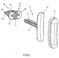
- Fig. 1 shows a perspective view of a breathing mask (1), which consists essentially of a mask body (2) made of a solid material and a mask cushion (3) made of a soft material.
- the mask cushion (3) can on a pad base (4) on an edge of the mask body (2) be plugged.
- the mask cushion (3) limited with sealing lips (5) a breathing opening (6), in when used by a patient, a nose of the Patients is introduced.
- a support leg (7) is attached, with a longitudinal axis (8) substantially parallel to one of the breathing opening (6) spanned Plane extends.
- the support leg (7) has a mounting opening (9) into which an adjusting device (10) is used.
- the adjusting device (10) has transversely to Longitudinal axis (8) has a guide recess (11) into which a Shank (12) of a support element (13) is inserted.
- the Support element (13) carries a forehead pad (14).
- the Forehead pad (14) substantially transverse to the longitudinal axis (8) extends.
- the mounting hole (9) is formed similar to a longitudinal slot, the extends in the direction of the longitudinal axis (8).
- Fig. 2 illustrates also that on the mask body (2) laterally two flanges (16) are formed, each with slit-shaped Recesses (17) are provided.
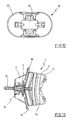
- adjusting device (10) with a base body (21) through the mounting opening (9) protrudes and with a plate (22) on the support leg (7).
- the main body (21) has resilient mounted clamping webs (23) on the shaft (12) of the Support element (13) within the guide recess (11) fix the adjusting device (10).
- FIG. 4 illustrates that the shank (12) in the region of its clamping webs (23) facing sides with a detent (24) is provided to Here, too, a defined and gradual positioning to allow the support element (13).
- Fig. 4 also illustrates that the support leg (7) essentially of a leg plate (25) as well Support webs (26), which is substantially perpendicular to Leg plate (25) are arranged and raised to an Flexural rigidity contribute. Rejuvenate the support webs (26) in a direction away from the mask body (2) and are in the area of their thickened ends on the mask body (2) molded.
- Fig. 5 illustrates in an exploded view the Construction of the adjusting device (10) and the support element (13).
- the support element (13) has a support plate (27) onto which the Forehead pad (14) is attached.
- the clamping webs (23) with locking projections (28) are provided, which engage in the detents (24) can.
- the clamping webs (23) are the locking projections (28) from the Latch (24) led out.
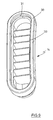
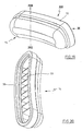
- Fig. 6 illustrates that the forehead pad (14) in the area an edge (30) provided with a U-profile (31) is that attachable to an edge (32) of the support plate (27) is.
- the forehead pad (14) provides for deployment a sufficient intrinsic stability inner Cross webs (33), which in an embodiment of the forehead pad (14) made of an elastomeric material to a good one Compromise between a sufficient dimensional stability and contribute to sufficient flexibility.
- FIG. 7 The illustration of the support element (13) in FIG. 7 illustrates that by the detent (24) a plurality of Grid compartments are trained, each for recording the locking projections (28) of the clamping webs (23) are provided are. It can also be seen that the support plate (27) slightly curved to adapt to the contour of a to ensure human forehead.
- the Forehead pad (14) has a hood-like cross-sectional design on and off the crossbars (33) are both Long sides of the forehead pad (14) supported relative to each other as well as a stiffening in the area of one the edge (30) turned away final rounding.
- FIG. 10 shows the adjusting device (10) in greater detail. It can be seen that the base body (21) in essentially consists of two plates (34, 35), between where the clamping webs (23) are arranged.
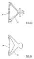
- Fig. 12 illustrates the combination of the adjusting device (10) with the shaft (12).
- Fig. 13 shows in a another side view as an assembly diagram of the combination the breathing mask (1) with a forehead pad (14), the via a shaft (12) of an adjusting device (10) is fixed in the region of the support leg (7).
- FIGS. 14 and 15 again show the structure of the adjusting device (10). Further illustrations of the adjustment (10) can also be found in Fig. 16 and in Fig. 17.
- Fig. 18 shows in a further perspective view again the support element (13), in particular recognizable in that the shaft (12) is similar to a cross-sectional profile to an I has.
- Fig. 19 and Fig. 20 show again in further perspective views the design the forehead pad (14).
- Fig. 21 illustrates that the forehead pad (14) substantially a symmetrical design to its longitudinal axis having.
- Fig. 22 illustrates the rounded outer Contouring of the forehead cushion (14).
- Fig. 23 shows a modified embodiment in which an elastomeric band (38) from a fork-like mount (39) is positioned.
- the elastomeric band (38) may become Adjust the contour of the forehead and the inclination of the forehead.
- FIG. 24 shows an embodiment modified from FIG. 23, FIG. in which the elastomeric band (38) and the holder (39) are made in one piece.
- a material e.g. Foam or a hollow body can be used.
- a typical adjustment procedure is such that the patient first the breathing mask (1) positioned in the area of his nose and in a first step, an adaptation to the Forehead height by a displacement of the adjustment (10) within the mounting opening (9) in the direction of Longitudinal axis (8) performs.
- About the detent (15) is a supported defined positioning.
- After a suitable Arrangement and locking of the adjusting device (10) within the mounting hole (9) is an adaptation to the Front distance by pulling out of the shaft (12) the guide recess (11) or by a pushing of the shaft (12) in the guide recess (11) performed.
Abstract
Description
Die Erfindung betrifft eine Vorrichtung zur Abstützung einer Atemmaske im Bereich einer Stirn eines Patienten, die mindestens ein im Bereich mindestens eines Halterungsschenkels der Atemmaske angeordnetes und über eine Verstelleinrichtung ein mit dem Halterungsschenkel verbundenes Stützelement aufweist.The invention relates to a device for supporting a Respiratory mask in the area of a forehead of a patient who at least one in the region of at least one support leg the breathing mask arranged and an adjusting device a support member connected to the support leg having.
Derartige Stützelemente mit Verstelleinrichtung dienen dazu, eine an eine jeweilige Gesichtsgeometrie des Patienten angepaßte Abstützung einer Atemmaske im Bereich einer Stirn des Patienten vorzunehmen. Die bekannten Stirnstützen weisen entweder eine Verstellmöglichkeit auf, um eine Verstellung im wesentlichen senkrecht zur Stirn vorzunehmen und hierdurch den wirksamen Stirnabstand zu verändern, oder um eine Verstellung im wesentlichen parallel zur Gesichtsfläche vorzunehmen und hierdurch eine Anpassung an die jeweilige Stirnhöhe durchzuführen. Bekannt sind hierzu mechanische Verstellungen oder der gezielte Einbau von Elementen mit einer relativ zueinander unterschiedlichen geeigneten Dimensionierung.Such support elements with adjusting serve to one to a respective facial geometry of the patient adapted support of a breathing mask in the region of a forehead of the patient. The known forehead supports point either an adjustment to an adjustment to make substantially perpendicular to the forehead and thereby changing the effective frontal distance, or around an adjustment substantially parallel to the facial surface make an adjustment to the respective Forehead height perform. Are known for this purpose mechanical Adjustments or the targeted installation of elements with a relative to each other different suitable Dimensioning.
Eine Stirnstütze mit einer Verstelleinrichtung zur Vorgabe eines wirksamen Stirnabstandes ist beispielsweise in der US-PS 61 19 693 beschrieben. Es wird hier eine brückenartige Stirnstütze offenbart, die über zwei Tragarme mit der Atemmaske verbunden ist. Ein Querträger des Stützelementes, der zwei Stirnpolster trägt, weist im Bereich seiner den Stützarmen zugewandten Ausdehnung Rastungen auf. Durch eine Arretierung der Stützarme in unterschiedlichen Rastungen wird ein unterschiedlicher Abstand des Querträgers zur Atemmaske und damit ein unterschiedlich wirksamer Stirnabstand vorgegeben.A forehead support with an adjustment for specification an effective frontal distance is for example in the US-PS 61 19 693 described. It becomes a bridge-like one here Forehead support disclosed, which has two support arms with the Respiratory mask is connected. A cross member of the support element, which carries two forehead pads, points in the area of his Low support facing extension detents. By a Locking of the support arms in different detents is a different distance of the cross member to Respiratory mask and thus a different effective frontal distance specified.
Die bislang bekannten Vorrichtungen können im Hinblick auf ihren Einstellkomfort und ihre Bedienbarkeit noch nicht alle Anforderungen erfüllen, die aus einer Verwendung durch den Patienten selbst resultieren.The hitherto known devices can with regard to their ease of adjustment and their usability not all Meet requirements resulting from use by result in the patient himself.
Aufgabe der vorliegenden Erfindung ist es daher, eine Vorrichtung der einleitend genannten Art derart zu konstruieren, daß eine vielseitige Einstellbarkeit bei gleichzeitig einfacher Bedienung bereit gestellt wird.Object of the present invention is therefore an apparatus of the type mentioned in the opening paragraph, that a versatile adjustability at the same time simple operation is provided.
Diese Aufgabe wird erfindungsgemäß dadurch gelöst, daß das Stirnpolster als ein elastomeres Band ausgebildet ist, das von einer gabelartigen Halterung positioniert ist. This object is achieved in that the Forehead pad is formed as an elastomeric band, the is positioned by a fork-like holder.
Zur Fixierung einer Adaption an eine jeweilige Stirnhöhe wird vorgeschlagen, daß für die Verstelleinrichtung eine Arretierung in Richtung der Längsachse vorgesehen ist.For fixing an adaptation to a respective frontal height It is proposed that for the adjusting a Arresting is provided in the direction of the longitudinal axis.
Zur Fixierung einer Adaption an einen jeweiligen Stirnabstand wird vorgeschlagen, daß für das Stützelement eine Arretierung quer zur Längsachse vorgesehen ist.For fixing an adaptation to a respective frontal distance It is proposed that for the support element a lock is provided transversely to the longitudinal axis.
Zur Erleichterung einer Einstellung ist vorgesehen, daß für die Führung der Verstelleinrichtung in Richtung der Längsachse eine Rastung vorgesehen ist.To facilitate a setting is provided that for the guidance of the adjusting device in the direction of the longitudinal axis a detent is provided.
Darüber hinaus ist auch daran gedacht, daß die Verstelleinrichtung in Richtung der Längsachse stufenlos verstellbar ist.In addition, it is also thought that the adjustment infinitely adjustable in the direction of the longitudinal axis is.
Eine weitere Bedienungserleichterung kann dadurch erreicht werden, daß für die Verstellung des Stützelementes quer zur Längsachse eine Rastung vorgesehen ist.A further ease of operation can be achieved be that for the adjustment of the support element transversely to Longitudinal axis a detent is provided.
Auch im Hinblick auf diese Verstellmöglichkeit ist daran gedacht, daß das Stützelement quer zur Längsachse stufenlos verstellbar ist.Also with regard to this adjustment is it thought that the support element transversely to the longitudinal axis stepless is adjustable.
Eine weiche Abpolsterung der Stirn kann dadurch erfolgen, daß das Stützelement ein Stirnpolster trägt, das als ein Gelkissen ausgebildet ist.A soft padding of the forehead can be done by that the support element carries a forehead pad, as a Gelkissen is formed.
Darüber hinaus ist daran gedacht, daß das Stützelement ein Stirnpolster trägt, das als ein elastomeres Polster ausgebildet ist.In addition, it is thought that the support element a Forehead pad wearing, which is designed as an elastomeric pad is.
Ebenfalls ist es möglich, daß das Stützelement ein Stirnpolster trägt, das als ein Schaumpolster ausgebildet ist. It is also possible that the support element is a forehead pad carries, which is designed as a foam pad.
Eine weitere Erhöhung der Einstellungsflexibilität kann dadurch erreicht werden, daß das Stützelement relativ zum Halterungsschenkel verschwenkbar angeordnet ist.A further increase of the adjustment flexibility can thereby be achieved, that the support element relative to Holding leg is arranged pivotably.
Ebenfalls ist daran gedacht, daß der Halterungsschenkel relativ zu einem Maskengrundkörper der Atemmaske verschwenkbar angeordnet ist.It is also thought that the support leg relative pivotable to a mask body of the breathing mask is arranged.
Eine weitere Anpassung an einen individuellen Patienten kann dadurch erreicht werden, daß das Stirnpolster in frontaler Richtung verkippbar angeordnet ist.Another adaptation to an individual patient can be achieved by the frontal pad in frontal Direction is arranged tilted.
Ein weiter gesteigerter Benutzungskomfort kann dadurch erreicht werden, daß das Stirnpolster seitlich kippbar angeordnet ist.A further increased ease of use can be achieved be that the forehead pad tiltably arranged laterally is.
Eine besonders gute Anpassung an eine Stirnkontur wird dadurch unterstützt, daß das Stirnpolster als ein elastomeres Band ausgebildet ist, das von einer gabelartigen Halterung positioniert ist.A particularly good adaptation to a front contour is characterized assists that the forehead pad as an elastomeric Band is formed by a fork-like bracket is positioned.
Gemäß einer weiteren Ausführungsvariante ist daran gedacht, daß das Stirnpolster als ein elastomeres Band ausgebildet ist, das einteilig mit einer gabelartigen Halterung konstruiert ist.According to a further embodiment, it is intended that the forehead pad is formed as an elastomeric band which is constructed in one piece with a fork-like mount is.
In den Zeichnungen sind Ausführungsbeispiele der Erfindung schematisch dargestellt. Es zeigen:
- Fig. 1
- Eine perspektivische Darstellung einer Atemmaske mit einem Stützelement, das sowohl in Richtung einer Längsachse eines Halterungsschenkels als auch quer zur Längsachse positionierbar ist,
- Fig. 2
- eine Ansicht gemäß Blickrichtung II in Fig. 1,
- Fig. 3
- eine Ansicht gemäß Blickrichtung III in Fig. 1,
- Fig. 4
- eine perspektivische Darstellung gemäß Blickrichtung IV in Fig. 3,
- Fig. 5
- eine Explosionsdarstellung des Stützelementes mit Stirnpolster und Verstelleinrichtung,
- Fig. 6
- eine Darstellung der Anordnung gemäß Blickrichtung VI in Fig. 5,
- Fig. 7
- eine vergrößerte perspektivische Darstellung des Stützelementes,
- Fig. 8
- eine Seitenansicht des Stützelementes gemäß Blickrichtung VIII in Fig. 7,
- Fig. 9
- eine vergrößerte perspektivische Darstellung des Stirnpolsters,
- Fig. 10
- eine vergrößerte perspektivische Darstellung der Verstelleinrichtung,
- Fig. 11
- eine Darstellung der Verstelleinrichtung gemäß Blickrichtung XI in Fig. 10,
- Fig. 12
- die Verstellvorrichtung gemäß Blickrichtung XII in Fig. 10,
- Fig. 13
- eine Seitenansicht gemäß Blickrichtung XIII in Fig. 1,
- Fig. 14
- eine weitere perspektivische Darstellung der Verstelleinrichtung,
- Fig. 15
- einen Längsschnitt gemäß Schnittlinie XV-XV in Fig. 11 nach einer Drehung um 90°,
- Fig. 16
- eine perspektivische Darstellung der Verstelleinrichtung gemäß Blickrichtung XVI in Fig. 14,
- Fig. 17
- eine weitere perspektivische Darstellung der Verstelleinrichtung,
- Fig. 18
- eine weitere perspektivische Darstellung des Stützelementes,
- Fig. 19
- eine weitere perspektivische Darstellung des Stirnpolsters,
- Fig. 20
- eine perspektivische Darstellung gemäß Blickrichtung XX in Fig. 19 nach einer Drehung um 90°,
- Fig. 21
- eine Ansicht gemäß Blickrichtung XXI in Fig. 19,
- Fig. 22
- einen Querschnitt gemäß Schnittlinie XXII-XXII in Fig. 19,
- Fig. 23
- eine Prinzipdarstellung einer brückenartigen Stirnstütze und
- Fig. 24
- eine gegenüber Fig. 23 abgewandelte Konstruktion einer brückenförmigen Stirnstütze in einteiliger Ausführung.
- Fig. 1
- A perspective view of a breathing mask with a support element, which can be positioned both in the direction of a longitudinal axis of a support leg and transversely to the longitudinal axis,
- Fig. 2
- a view according to the viewing direction II in Fig. 1,
- Fig. 3
- a view according to the viewing direction III in Fig. 1,
- Fig. 4
- a perspective view according to viewing direction IV in Fig. 3,
- Fig. 5
- an exploded view of the support element with forehead cushion and adjustment,
- Fig. 6
- a representation of the arrangement according to viewing direction VI in Fig. 5,
- Fig. 7
- an enlarged perspective view of the support element,
- Fig. 8
- a side view of the support element according to viewing direction VIII in Fig. 7,
- Fig. 9
- an enlarged perspective view of the forehead pad,
- Fig. 10
- an enlarged perspective view of the adjusting device,
- Fig. 11
- a representation of the adjusting device according to the viewing direction XI in Fig. 10,
- Fig. 12
- the adjusting device according to the viewing direction XII in Fig. 10,
- Fig. 13
- a side view according to the viewing direction XIII in Fig. 1,
- Fig. 14
- another perspective view of the adjustment,
- Fig. 15
- a longitudinal section along section line XV-XV in Figure 11 after a rotation of 90 °,
- Fig. 16
- 3 is a perspective view of the adjusting device according to the viewing direction XVI in FIG. 14,
- Fig. 17
- another perspective view of the adjustment,
- Fig. 18
- another perspective view of the support element,
- Fig. 19
- another perspective view of the forehead pad,
- Fig. 20
- a perspective view according to viewing direction XX in FIG. 19 after a rotation through 90 °,
- Fig. 21
- a view according to the viewing direction XXI in Fig. 19,
- Fig. 22
- a cross section according to section line XXII-XXII in Fig. 19,
- Fig. 23
- a schematic diagram of a bridge-like forehead support and
- Fig. 24
- a comparison with Fig. 23 modified construction of a bridge-shaped forehead support in one-piece design.
Fig. 1 zeigt eine perspektivische Darstellung einer Atemmaske (1), die im wesentlichen aus einem Maskengrundkörper (2) aus einem festen Material und einem Maskenpolster (3) aus einem weichen Material besteht. Das Maskenpolster (3) kann über einen Polstersockel (4) auf einen Rand des Maskengrundkörpers (2) aufgesteckt sein. Das Maskenpolster (3) begrenzt mit Dichtungslippen (5) eine Atemöffnung (6), in die bei einer Benutzung durch einen Patienten eine Nase des Patienten eingeführt wird.Fig. 1 shows a perspective view of a breathing mask (1), which consists essentially of a mask body (2) made of a solid material and a mask cushion (3) made of a soft material. The mask cushion (3) can on a pad base (4) on an edge of the mask body (2) be plugged. The mask cushion (3) limited with sealing lips (5) a breathing opening (6), in when used by a patient, a nose of the Patients is introduced.
Am Maskengrundkörper (2) ist ein Halterungsschenkel (7) befestigt, der sich mit einer Längsachse (8) im wesentlichen parallel zu einer von der Atemöffnung (6) aufgespannten Ebene erstreckt. Der Halterungsschenkel (7) weist eine Montageöffnung (9) auf, in die eine Verstelleinrichtung (10) eingesetzt ist. Die Verstelleinrichtung (10) weist quer zur Längsachse (8) eine Führungsausnehmung (11) auf, in die ein Schaft (12) eines Stützelementes (13) eingeführt ist. Das Stützelement (13) trägt ein Stirnpolster (14).On the mask body (2) a support leg (7) is attached, with a longitudinal axis (8) substantially parallel to one of the breathing opening (6) spanned Plane extends. The support leg (7) has a mounting opening (9) into which an adjusting device (10) is used. The adjusting device (10) has transversely to Longitudinal axis (8) has a guide recess (11) into which a Shank (12) of a support element (13) is inserted. The Support element (13) carries a forehead pad (14).
Aus der Darstellung in Fig. 2 ist erkennbar, daß sich das Stirnpolster (14) im wesentlichen quer zur Längsachse (8) erstreckt. Ebenfalls ist zu erkennen, daß die Montageöffnung (9) ähnlich zu einem Längsschlitz ausgebildet ist, der sich in Richtung der Längsachse (8) erstreckt. Gemäß der Ausführungsform in Fig. 1 und Fig. 2 weist die Montageöffnung (9) mehrere Rastungen (15) auf, um eine stufenweise definierte Positionierung der Verstelleinrichtung (10) in Richtung der Längsachse (8) zu unterstützen. Fig. 2 veranschaulicht ebenfalls, daß am Maskengrundkörper (2) seitlich zwei Flansche (16) angeformt sind, die jeweils mit schlitzförmigen Ausnehmungen (17) versehen sind. From the illustration in Fig. 2 it can be seen that the Forehead pad (14) substantially transverse to the longitudinal axis (8) extends. It can also be seen that the mounting hole (9) is formed similar to a longitudinal slot, the extends in the direction of the longitudinal axis (8). According to the Embodiment in Fig. 1 and Fig. 2 has the mounting hole (9) a plurality of notches (15) to a stepwise defined positioning of the adjusting device (10) in Support direction of the longitudinal axis (8). Fig. 2 illustrates also that on the mask body (2) laterally two flanges (16) are formed, each with slit-shaped Recesses (17) are provided.
Alternativ zu einer Verwendung von Rastungen (15) ist es auch denkbar, für die Positionierung der Verstelleinrichtung (10) in Richtung der Längsachse (8) mehrere Aufnahmen im Bereich des Halterungsschenkels (7) anzuordnen und die Verstelleinrichtung (10) jeweils in eine dieser Aufnahmen einzusetzen.Alternatively to a use of detents (15) it is also conceivable for the positioning of the adjusting device (10) in the direction of the longitudinal axis (8) several shots to arrange in the region of the support leg (7) and the Adjustment (10) each in one of these shots use.
Im Bereich des Halterungsschenkels (7) sind seitlich zwei Ausnehmungen (18) und im Bereich eines Endsegmentes (19) ist eine hufeisenartige Ausnehmung (20) angeordnet.In the region of the support leg (7) are two laterally Recesses (18) and in the region of an end segment (19) a horseshoe-like recess (20) is arranged.
Aus Fig. 3 ist erkennbar, daß die Verstelleinrichtung (10) mit einem Grundkörper (21) durch die Montageöffnung (9) hindurchragt und mit einer Platte (22) auf dem Halterungsschenkel (7) aufliegt. Der Grundkörper (21) weist federnd gelagerte Klemmstege (23) auf, die den Schaft (12) des Stützelementes (13) innerhalb der Führungsausnehmung (11) der Verstelleinrichtung (10) fixieren.From Fig. 3 it can be seen that the adjusting device (10) with a base body (21) through the mounting opening (9) protrudes and with a plate (22) on the support leg (7). The main body (21) has resilient mounted clamping webs (23) on the shaft (12) of the Support element (13) within the guide recess (11) fix the adjusting device (10).
Die perspektivische Darstellung in Fig. 4 veranschaulicht, daß der Schaft (12) im Bereich seiner den Klemmstegen (23) zugewandten Seiten mit einer Rastung (24) versehen ist, um auch hier eine definierte und schrittweise Positionierung des Stützelementes (13) zu ermöglichen.The perspective view in FIG. 4 illustrates that the shank (12) in the region of its clamping webs (23) facing sides with a detent (24) is provided to Here, too, a defined and gradual positioning to allow the support element (13).
Fig. 4 veranschaulicht ebenfalls, daß der Halterungsschenkel (7) im wesentlichen aus einer Schenkelplatte (25) sowie Stützstegen (26) besteht, die im wesentlichen senkrecht zur Schenkelplatte (25) angeordnet sind und zu einer erhöhten Biegesteifigkeit beitragen. Die Stützstege (26) verjüngen sich in eine dem Maskengrundkörper (2) abgewandte Richtung und sind im Bereich ihrer verdickten Enden am Maskengrundkörper (2) angeformt. Fig. 4 also illustrates that the support leg (7) essentially of a leg plate (25) as well Support webs (26), which is substantially perpendicular to Leg plate (25) are arranged and raised to an Flexural rigidity contribute. Rejuvenate the support webs (26) in a direction away from the mask body (2) and are in the area of their thickened ends on the mask body (2) molded.
Fig. 5 veranschaulicht in einer Explosionsdarstellung die Konstruktion der Verstelleinrichtung (10) und des Stützelementes (13). Insbesondere ist erkennbar, daß das Stützelement (13) eine Stützplatte (27) aufweist, auf die das Stirnpolster (14) aufgesteckt wird. Ebenfalls ist aus Fig. 5 zu erkennen, daß die Klemmstege (23) mit Rastvorsprüngen (28) versehen sind, die in die Rastungen (24) eingreifen können. Bei einem manuellen Druck auf Bedienflächen (29) der Klemmstege (23) werden die Rastvorsprünge (28) aus der Rastung (24) herausgeführt.Fig. 5 illustrates in an exploded view the Construction of the adjusting device (10) and the support element (13). In particular, it can be seen that the support element (13) has a support plate (27) onto which the Forehead pad (14) is attached. Also, from FIG. 5 to recognize that the clamping webs (23) with locking projections (28) are provided, which engage in the detents (24) can. When manually pressing on control surfaces (29) the clamping webs (23) are the locking projections (28) from the Latch (24) led out.
Fig. 6 veranschaulicht, daß das Stirnpolster (14) im Bereich eines Randes (30) mit einem U-Profil (31) versehen ist, das auf einen Rand (32) der Stützplatte (27) aufsteckbar ist. Darüber hinaus weist das Stirnpolster (14) zur Bereitstellung einer ausreichenden Eigenstabilität innere Querstege (33) auf, die bei einer Ausbildung des Stirnpolsters (14) aus einem elastomeren Material zu einem guten Kompromiß zwischen einer ausreichenden Formstabilität und einer ausreichenden Nachgiebigkeit beitragen.Fig. 6 illustrates that the forehead pad (14) in the area an edge (30) provided with a U-profile (31) is that attachable to an edge (32) of the support plate (27) is. In addition, the forehead pad (14) provides for deployment a sufficient intrinsic stability inner Cross webs (33), which in an embodiment of the forehead pad (14) made of an elastomeric material to a good one Compromise between a sufficient dimensional stability and contribute to sufficient flexibility.
Die Darstellung des Stützelementes (13) in Fig. 7 veranschaulicht, daß durch die Rastung (24) eine Vielzahl von Rasterfächern ausgebildet werden, die jeweils zur Aufnahme der Rastvorsprünge (28) der Klemmstege (23) vorgesehen sind. Ebenfalls ist erkennbar, daß die Stützplatte (27) leicht gewölbt ist, um eine Anpassung an die Kontur einer menschlichen Stirn zu gewährleisten.The illustration of the support element (13) in FIG. 7 illustrates that by the detent (24) a plurality of Grid compartments are trained, each for recording the locking projections (28) of the clamping webs (23) are provided are. It can also be seen that the support plate (27) slightly curved to adapt to the contour of a to ensure human forehead.
Die Wölbung der Stützplatte (27) sowie die Anordnung der Rastung (24) entlang der Längserstreckung des Schaftes (12) wird in Fig. 8 noch einmal veranschaulicht. The curvature of the support plate (27) and the arrangement of Detent (24) along the longitudinal extent of the shaft (12) is illustrated once again in FIG.
Aus der Darstellung in Fig. 9 ist der Aufbau des Stirnpolsters (14) in größerer Detailliertheit zu erkennen. Das Stirnpolster (14) weist eine haubenartige Querschnittgestaltung auf und von den Querstegen (33) werden sowohl Längsseiten des Stirnpolsters (14) relativ zueinander abgestützt als auch eine Versteifung im Bereich einer dem Rand (30) abgewandten Abschlußrundung hervorgerufen.From the illustration in Fig. 9 is the structure of the forehead pad (14) to recognize in greater detail. The Forehead pad (14) has a hood-like cross-sectional design on and off the crossbars (33) are both Long sides of the forehead pad (14) supported relative to each other as well as a stiffening in the area of one the edge (30) turned away final rounding.
Die vergrößerte perspektivische Darstellung in Fig. 10 zeigt die Verstelleinrichtung (10) in stärkerer Detailliertheit. Es ist zu erkennen, daß der Grundkörper (21) im wesentlichen aus zwei Platten (34, 35) besteht, zwischen denen die Klemmstege (23) angeordnet sind.The enlarged perspective view in FIG. 10 shows the adjusting device (10) in greater detail. It can be seen that the base body (21) in essentially consists of two plates (34, 35), between where the clamping webs (23) are arranged.
Aus Fig. 11 ist zu erkennen, daß an den Platten (34, 35) Querstege (36, 37) angeordnet sind, die sich in Richtung auf die Klemmstege (23) erstrecken.From Fig. 11 it can be seen that on the plates (34, 35) Transverse webs (36, 37) are arranged, extending in the direction extend to the clamping webs (23).
Fig. 12 veranschaulicht die Kombination der Verstelleinrichtung (10) mit dem Schaft (12). Fig. 13 zeigt in einer weiteren Seitenansicht als Zusammenbaudarstellung die Kombination der Atemmaske (1) mit einem Stirnpolster (14), das über einen Schaft (12) von einer Verstelleinrichtung (10) im Bereich des Halterungsschenkels (7) fixiert ist.Fig. 12 illustrates the combination of the adjusting device (10) with the shaft (12). Fig. 13 shows in a another side view as an assembly diagram of the combination the breathing mask (1) with a forehead pad (14), the via a shaft (12) of an adjusting device (10) is fixed in the region of the support leg (7).
Fig. 14 und Fig. 15 zeigen nochmals den Aufbau der Verstelleinrichtung (10). Weitere Darstellungen der Verstelleinrichtung (10) finden sich auch in Fig. 16 und in Fig. 17.FIGS. 14 and 15 again show the structure of the adjusting device (10). Further illustrations of the adjustment (10) can also be found in Fig. 16 and in Fig. 17.
Fig. 18 zeigt in einer weiteren perspektivischen Darstellung nochmals das Stützelement (13), wobei insbesondere erkennbar ist, daß der Schaft (12) ein Querschnittprofil ähnlich zu einem I aufweist. Fig. 19 und Fig. 20 zeigen nochmals in weiteren perspektivischen Darstellungen die Gestaltung des Stirnpolsters (14).Fig. 18 shows in a further perspective view again the support element (13), in particular recognizable in that the shaft (12) is similar to a cross-sectional profile to an I has. Fig. 19 and Fig. 20 show again in further perspective views the design the forehead pad (14).
Fig. 21 veranschaulicht, daß das Stirnpolster (14) im wesentlichen eine symmetrische Gestaltung zu seiner Längsachse aufweist. Fig. 22 veranschaulicht die gerundete äußere Konturierung des Stirnpolsters (14).Fig. 21 illustrates that the forehead pad (14) substantially a symmetrical design to its longitudinal axis having. Fig. 22 illustrates the rounded outer Contouring of the forehead cushion (14).
Fig. 23 zeigt eine modifizierte Ausführungsform, bei der ein elastomeres Band (38) von einer gabelartigen Halterung (39) positioniert ist. Das elastomere Band (38) kann sich der Stirnkontur und der Stirnneigung anpassen.Fig. 23 shows a modified embodiment in which an elastomeric band (38) from a fork-like mount (39) is positioned. The elastomeric band (38) may become Adjust the contour of the forehead and the inclination of the forehead.
Fig. 24 zeigt eine zur Fig. 23 modifizierte Ausführungsform, bei der das elastomere Band (38) und die Halterung (39) einteilig ausgeführt sind. Als Werkstoff kann z.B. Schaum oder ein Hohlkörper verwendet werden.FIG. 24 shows an embodiment modified from FIG. 23, FIG. in which the elastomeric band (38) and the holder (39) are made in one piece. As a material, e.g. Foam or a hollow body can be used.
Ein typischer Einstellvorgang erfolgt derart, daß der Patient zunächst die Atemmaske (1) im Bereich seiner Nase positioniert und in einem ersten Schritt eine Anpassung an die Stirnhöhe durch eine Verschiebung der Verstelleinrichtung (10) innerhalb der Montageöffnung (9) in Richtung der Längsachse (8) durchführt. Über die Rastung (15) wird eine definierte Positionierung unterstützt. Nach einer geeigneten Anordnung und Arretierung der Verstelleinrichtung (10) innerhalb der Montageöffnung (9) wird eine Anpassung an den Stirnabstand durch ein Herausziehen des Schaftes (12) aus der Führungsausnehmung (11) bzw. durch ein Hineinschieben des Schaftes (12) in die Führungsausnehmung (11) durchgeführt. Vor dieser Positionierung werden durch einen Druck auf die Bedienflächen (29) der Klemmstege (23) die Rastvorsprünge (28) aus den Vertiefungen der Rastung (24) herausgeschwenkt. Nach einer geeigneten Positionierung des Schaftes (12) des Stützelementes (13) werden die Bedienflächen (29) losgelassen und die Rastvorsprünge (28) federn in die Rastung (24) zurück. Hierdurch ist das Stützelement (13) in seiner aktuellen Positionierung arretiert.A typical adjustment procedure is such that the patient first the breathing mask (1) positioned in the area of his nose and in a first step, an adaptation to the Forehead height by a displacement of the adjustment (10) within the mounting opening (9) in the direction of Longitudinal axis (8) performs. About the detent (15) is a supported defined positioning. After a suitable Arrangement and locking of the adjusting device (10) within the mounting hole (9) is an adaptation to the Front distance by pulling out of the shaft (12) the guide recess (11) or by a pushing of the shaft (12) in the guide recess (11) performed. Prior to this positioning are by a pressure on the control surfaces (29) of the clamping webs (23), the latching projections (28) from the recesses of the detent (24) swung out. After a suitable positioning of the shaft (12) of the support element (13) are the control surfaces (29) released and the latching projections (28) spring into the Latch (24) back. As a result, the support element (13) in its current positioning locked.
Sollte eine nachträgliche Veränderung der gewählten Positionierungen erforderlich sein, so kann sowohl eine Änderung der Stirnhöheneinstellung als auch eine Änderung der Stirnabstandseinstellung ohne Rückwirkung auf die jeweils andere Einstellung erfolgen. Die erläuterten Arretierungen vermeiden eine ungewollte Veränderung der Positionierung des Stützelementes (13) während der Benutzung.Should a subsequent change in the selected positions may be required, so can be both a change the forehead height adjustment as well as a change of the Front distance adjustment without retroacting on each other setting done. The explained detents avoid an unwanted change of positioning the support element (13) during use.
Claims (16)
Applications Claiming Priority (3)
| Application Number | Priority Date | Filing Date | Title |
|---|---|---|---|
| DE10056331 | 2000-11-14 | ||
| DE10056331 | 2000-11-14 | ||
| EP01126897A EP1205205B1 (en) | 2000-11-14 | 2001-11-12 | Respiratory mask with forehead support |
Related Parent Applications (1)
| Application Number | Title | Priority Date | Filing Date |
|---|---|---|---|
| EP01126897A Division EP1205205B1 (en) | 2000-11-14 | 2001-11-12 | Respiratory mask with forehead support |
Publications (3)
| Publication Number | Publication Date |
|---|---|
| EP1493461A2 true EP1493461A2 (en) | 2005-01-05 |
| EP1493461A3 EP1493461A3 (en) | 2005-01-12 |
| EP1493461B1 EP1493461B1 (en) | 2006-10-04 |
Family
ID=7663217
Family Applications (3)
| Application Number | Title | Priority Date | Filing Date |
|---|---|---|---|
| EP04022931.2A Expired - Lifetime EP1493462B1 (en) | 2000-11-14 | 2001-11-12 | Respiratory mask with forehead support |
| EP01126897A Expired - Lifetime EP1205205B1 (en) | 2000-11-14 | 2001-11-12 | Respiratory mask with forehead support |
| EP04022930A Expired - Lifetime EP1493461B1 (en) | 2000-11-14 | 2001-11-12 | Breathing mask with a forehead support |
Family Applications Before (2)
| Application Number | Title | Priority Date | Filing Date |
|---|---|---|---|
| EP04022931.2A Expired - Lifetime EP1493462B1 (en) | 2000-11-14 | 2001-11-12 | Respiratory mask with forehead support |
| EP01126897A Expired - Lifetime EP1205205B1 (en) | 2000-11-14 | 2001-11-12 | Respiratory mask with forehead support |
Country Status (3)
| Country | Link |
|---|---|
| EP (3) | EP1493462B1 (en) |
| AT (2) | ATE341359T1 (en) |
| DE (4) | DE50111169D1 (en) |
Cited By (4)
| Publication number | Priority date | Publication date | Assignee | Title |
|---|---|---|---|---|
| DE102005042180A1 (en) * | 2004-09-03 | 2006-05-04 | Weinmann Geräte für Medizin GmbH & Co. KG | Respiratory device for use by patient, is formed as part of user interface, where two components of interface are connected together by manually detachable interlock and interface is formed as respiratory mask |
| WO2010133218A3 (en) * | 2009-05-18 | 2011-03-17 | Weinmann Geräte für Medizin GmbH + Co. KG | Respiratory device comprising a fastening system |
| CN101472637B (en) * | 2006-06-16 | 2012-01-11 | 雷斯梅德有限公司 | Forehead supports for facial masks |
| WO2012156845A1 (en) * | 2011-05-17 | 2012-11-22 | Koninklijke Philips Electronics N.V. | Adjustable locking forehead support for a patient interface device |
Families Citing this family (32)
| Publication number | Priority date | Publication date | Assignee | Title |
|---|---|---|---|---|
| DE20017940U1 (en) | 2000-10-19 | 2000-12-28 | Map Gmbh | Breathing mask for supplying a breathing gas to a mask user and a derivation device for deriving breathing gas |
| DE10201682A1 (en) | 2002-01-17 | 2003-07-31 | Map Medizin Technologie Gmbh | The breathing mask arrangement |
| DE10151984C5 (en) | 2001-10-22 | 2008-07-17 | Map Medizin-Technologie Gmbh | Application device for a breathing mask arrangement |
| JP4430935B2 (en) | 2001-10-22 | 2010-03-10 | エムアーペー メディツィンテクノロジー ゲゼルシャフト・ミット・ベシュレンクテル・ハフツング | Respirator apparatus, wearing device for respirator apparatus, and forehead support |
| JP4434961B2 (en) | 2002-09-06 | 2010-03-17 | レスメド・リミテッド | Forehead pad for respirator |
| WO2004052438A1 (en) | 2002-12-06 | 2004-06-24 | Fisher & Paykel Healthcare Limited | Mouthpiece |
| US7503327B2 (en) | 2003-04-10 | 2009-03-17 | Resmed Limited | Mask with integral cushion and forehead piece |
| AU2004234183B2 (en) | 2003-05-02 | 2011-01-20 | Resmed Limited | A mask system |
| WO2005009521A1 (en) | 2003-07-30 | 2005-02-03 | Fisher & Paykel Healthcare Limited | Forehead rest for respiratory masks |
| DE102004002870B4 (en) | 2004-01-19 | 2017-01-19 | Löwenstein Medical Technology S.A. | Respiratory mask with forehead support |
| NZ608551A (en) | 2004-06-16 | 2014-10-31 | Resmed Ltd | Cushion for a respiratory mask assembly |
| EP1841481B1 (en) | 2005-01-12 | 2015-12-02 | ResMed Limited | Cushion for patient interface |
| CN103007406B (en) * | 2005-01-12 | 2016-09-14 | 瑞思迈有限公司 | The forehead supports of facial masks |
| US8171934B1 (en) * | 2005-07-15 | 2012-05-08 | Ric Investments, Llc | Forehead pad and forehead support assembly |
| US8397728B2 (en) | 2005-10-14 | 2013-03-19 | Resmed Limited | Cushion to frame assembly mechanism |
| US20090126739A1 (en) | 2005-10-25 | 2009-05-21 | Resmed Limited | Interchangeable Mask Assembly |
| US9387301B2 (en) | 2006-12-19 | 2016-07-12 | Koninklijke Philips N.V. | Pad assembly having outer casing and support element |
| US8517023B2 (en) | 2007-01-30 | 2013-08-27 | Resmed Limited | Mask system with interchangeable headgear connectors |
| NZ589685A (en) | 2007-04-19 | 2012-06-29 | Resmed Ltd | Cushion for patient breathing interface with variable density foam supported membrane |
| US9707367B2 (en) * | 2007-06-21 | 2017-07-18 | Resmed Limited | Auto-adjusting mask stabilizer |
| US11331447B2 (en) | 2008-03-04 | 2022-05-17 | ResMed Pty Ltd | Mask system with snap-fit shroud |
| NZ792157A (en) | 2008-03-04 | 2022-11-25 | ResMed Pty Ltd | Mask system |
| CN102019022B (en) * | 2009-09-21 | 2013-05-22 | 新广业股份有限公司 | Breathing mask |
| WO2011080605A1 (en) * | 2009-12-28 | 2011-07-07 | Koninklijke Philips Electronics N.V. | Pad assembly having outer casing and support element |
| WO2012127359A1 (en) * | 2011-03-21 | 2012-09-27 | Koninklijke Philips Electronics N.V. | Helical forehead support adjustment mechanism |
| EP2601993B1 (en) * | 2011-12-07 | 2018-02-14 | Löwenstein Medical Technology S.A. | Device for positioning a patient interface |
| CN203107935U (en) * | 2011-12-29 | 2013-08-07 | 皇家飞利浦电子股份有限公司 | Patient interface system with adjustable forehead supporting part |
| RU2649462C2 (en) * | 2012-07-11 | 2018-04-03 | Конинклейке Филипс Н.В. | Patient interface |
| US9775961B2 (en) | 2012-07-11 | 2017-10-03 | Koninklijke Philips N.V. | Patient interface |
| CN103536996B (en) * | 2013-10-25 | 2015-10-28 | 长沙比扬医疗器械有限公司 | A kind of breathing mask forehead support frame and there is the breathing mask of this bracing frame |
| CN103961776B (en) * | 2014-05-30 | 2017-03-15 | 北京怡和嘉业医疗科技有限公司 | Breathing mask, mask forehead support and mask frame |
| DE102019131147A1 (en) | 2018-11-30 | 2020-06-04 | Löwenstein Medical Technology S.A. | Device for supporting a breathing mask with integral functional elements |
Citations (3)
| Publication number | Priority date | Publication date | Assignee | Title |
|---|---|---|---|---|
| US2245658A (en) * | 1937-10-15 | 1941-06-17 | Clarence N Erickson | Inhaling device |
| DE29923126U1 (en) * | 1998-06-17 | 2000-03-30 | Mpv Truma Ges Fuer Medizintech | Nasal breathing mask and breathing tube |
| US6119693A (en) * | 1998-01-16 | 2000-09-19 | Resmed Limited | Forehead support for facial mask |
Family Cites Families (4)
| Publication number | Priority date | Publication date | Assignee | Title |
|---|---|---|---|---|
| US2664084A (en) * | 1951-01-26 | 1953-12-29 | Hammermann Herbert | Anesthetic apparatus |
| US5042478A (en) * | 1988-08-26 | 1991-08-27 | University Technologies International, Inc. | Method of ventilation using nares seal |
| DE9420841U1 (en) * | 1994-12-30 | 1995-03-23 | Mahlo Hans Wolfgang Dr | Breathing mask for temporary contact with the nose area of a patient |
| AUPP949999A0 (en) * | 1999-03-29 | 1999-04-22 | Resmed Limited | Forehead support for facial mask II |
-
2001
- 2001-11-12 DE DE50111169T patent/DE50111169D1/en not_active Expired - Lifetime
- 2001-11-12 EP EP04022931.2A patent/EP1493462B1/en not_active Expired - Lifetime
- 2001-11-12 EP EP01126897A patent/EP1205205B1/en not_active Expired - Lifetime
- 2001-11-12 DE DE50106508T patent/DE50106508D1/en not_active Expired - Lifetime
- 2001-11-12 AT AT04022930T patent/ATE341359T1/en not_active IP Right Cessation
- 2001-11-12 DE DE20122300U patent/DE20122300U1/en not_active Expired - Lifetime
- 2001-11-12 DE DE10155152A patent/DE10155152A1/en not_active Withdrawn
- 2001-11-12 AT AT01126897T patent/ATE297777T1/en not_active IP Right Cessation
- 2001-11-12 EP EP04022930A patent/EP1493461B1/en not_active Expired - Lifetime
Patent Citations (3)
| Publication number | Priority date | Publication date | Assignee | Title |
|---|---|---|---|---|
| US2245658A (en) * | 1937-10-15 | 1941-06-17 | Clarence N Erickson | Inhaling device |
| US6119693A (en) * | 1998-01-16 | 2000-09-19 | Resmed Limited | Forehead support for facial mask |
| DE29923126U1 (en) * | 1998-06-17 | 2000-03-30 | Mpv Truma Ges Fuer Medizintech | Nasal breathing mask and breathing tube |
Cited By (10)
| Publication number | Priority date | Publication date | Assignee | Title |
|---|---|---|---|---|
| DE102005042180A1 (en) * | 2004-09-03 | 2006-05-04 | Weinmann Geräte für Medizin GmbH & Co. KG | Respiratory device for use by patient, is formed as part of user interface, where two components of interface are connected together by manually detachable interlock and interface is formed as respiratory mask |
| CN101472637B (en) * | 2006-06-16 | 2012-01-11 | 雷斯梅德有限公司 | Forehead supports for facial masks |
| WO2010133218A3 (en) * | 2009-05-18 | 2011-03-17 | Weinmann Geräte für Medizin GmbH + Co. KG | Respiratory device comprising a fastening system |
| US8967148B2 (en) | 2009-05-18 | 2015-03-03 | Weinmann Gerate Fur Medizin Gmbh & Co. Kg | Respiratory device comprising a fastening system |
| EP2716320A3 (en) * | 2009-05-18 | 2018-01-17 | Löwenstein Medical Technology S.A. | Device for positioning a patient interface |
| US10046132B2 (en) | 2009-05-18 | 2018-08-14 | Loewenstein Medical Technology S.A. | Respiratory device comprising a fastening system |
| WO2012156845A1 (en) * | 2011-05-17 | 2012-11-22 | Koninklijke Philips Electronics N.V. | Adjustable locking forehead support for a patient interface device |
| JP2014516685A (en) * | 2011-05-17 | 2014-07-17 | コーニンクレッカ フィリップス エヌ ヴェ | Adjustable locked forehead support for patient interface devices |
| RU2604700C2 (en) * | 2011-05-17 | 2016-12-10 | Конинклейке Филипс Н.В. | Adjustable locking forehead support for a patient interface device |
| US9744326B2 (en) | 2011-05-17 | 2017-08-29 | Koninklijke Philips N.V. | Adjustable locking forehead support for a patient interface device |
Also Published As
| Publication number | Publication date |
|---|---|
| ATE341359T1 (en) | 2006-10-15 |
| DE10155152A1 (en) | 2002-06-27 |
| EP1205205A2 (en) | 2002-05-15 |
| EP1205205B1 (en) | 2005-06-15 |
| EP1493462A2 (en) | 2005-01-05 |
| DE50106508D1 (en) | 2005-07-21 |
| EP1205205A3 (en) | 2003-12-10 |
| ATE297777T1 (en) | 2005-07-15 |
| EP1493462A3 (en) | 2005-01-12 |
| EP1493462B1 (en) | 2019-07-24 |
| DE50111169D1 (en) | 2006-11-16 |
| DE20122300U1 (en) | 2005-02-03 |
| EP1493461A3 (en) | 2005-01-12 |
| EP1493461B1 (en) | 2006-10-04 |
Similar Documents
| Publication | Publication Date | Title |
|---|---|---|
| EP1493462B1 (en) | Respiratory mask with forehead support | |
| EP2716320B1 (en) | Device for positioning a patient interface | |
| EP0535552B1 (en) | Headband for measuring, lighting or viewing device | |
| EP1562529B1 (en) | Headrest for a patient-bearing surface | |
| EP1904002A1 (en) | Trunk orthosis | |
| DE2502202B2 (en) | Support bodice | |
| EP0301368A1 (en) | Cervical support | |
| EP1898858B1 (en) | Arm rest | |
| EP3373773A1 (en) | Portable headrest for body positions lying on the stomach, for self-application and as an therapeutic aid | |
| EP0301369A1 (en) | Cervical support | |
| DE10254399B4 (en) | Headband assembly for applying a breathing mask | |
| EP2783728B1 (en) | Therapy device for the treatment of respiratory diseases | |
| DE3900004C2 (en) | Padded fixation tape for tracheostomy tubes | |
| EP1266674B1 (en) | Support device | |
| DE19547115A1 (en) | Collar for neck support | |
| DE2556757C2 (en) | Back support bandage with a pad | |
| DE102020132128A1 (en) | Back orthosis and kit for a back orthosis | |
| WO1986005091A1 (en) | Back support for use in physiotherapy in spinal disorders | |
| DE102020120889A1 (en) | Device for avoiding narrowing or obstruction of a sleeping person's airway | |
| EP0578224B1 (en) | Operating platform | |
| DE2555487A1 (en) | Spinal traction therapy system - has twin section jaw support and rear support connected to main traction cable through ring and cord system | |
| DE10245977C2 (en) | Pelvic fixation for a seat of a physically handicapped person | |
| DE102019212410A1 (en) | Orthosis for producing supination and / or pronation | |
| DE60016711T2 (en) | exercise machine | |
| DE1589524A1 (en) | Device for applying electrodes to the head of a patient |
Legal Events
| Date | Code | Title | Description |
|---|---|---|---|
| PUAI | Public reference made under article 153(3) epc to a published international application that has entered the european phase |
Free format text: ORIGINAL CODE: 0009012 |
|
| PUAL | Search report despatched |
Free format text: ORIGINAL CODE: 0009013 |
|
| 17P | Request for examination filed |
Effective date: 20040927 |
|
| AC | Divisional application: reference to earlier application |
Ref document number: 1205205 Country of ref document: EP Kind code of ref document: P |
|
| AK | Designated contracting states |
Kind code of ref document: A2 Designated state(s): AT BE CH CY DE DK ES FI FR GB GR IE IT LI LU MC NL PT SE TR |
|
| AK | Designated contracting states |
Kind code of ref document: A3 Designated state(s): AT BE CH CY DE DK ES FI FR GB GR IE IT LI LU MC NL PT SE TR |
|
| RIN1 | Information on inventor provided before grant (corrected) |
Inventor name: SCHULZ, GERD Inventor name: EIFLER, MARTIN |
|
| AKX | Designation fees paid |
Designated state(s): AT BE CH CY DE DK ES FI FR GB GR IE IT LI LU MC NL PT SE TR |
|
| RTI1 | Title (correction) |
Free format text: BREATHING MASK WITH A FOREHEAD SUPPORT |
|
| GRAP | Despatch of communication of intention to grant a patent |
Free format text: ORIGINAL CODE: EPIDOSNIGR1 |
|
| GRAS | Grant fee paid |
Free format text: ORIGINAL CODE: EPIDOSNIGR3 |
|
| GRAA | (expected) grant |
Free format text: ORIGINAL CODE: 0009210 |
|
| AC | Divisional application: reference to earlier application |
Ref document number: 1205205 Country of ref document: EP Kind code of ref document: P |
|
| AK | Designated contracting states |
Kind code of ref document: B1 Designated state(s): AT BE CH CY DE DK ES FI FR GB GR IE IT LI LU MC NL PT SE TR |
|
| PG25 | Lapsed in a contracting state [announced via postgrant information from national office to epo] |
Ref country code: FI Free format text: LAPSE BECAUSE OF FAILURE TO SUBMIT A TRANSLATION OF THE DESCRIPTION OR TO PAY THE FEE WITHIN THE PRESCRIBED TIME-LIMIT Effective date: 20061004 Ref country code: NL Free format text: LAPSE BECAUSE OF FAILURE TO SUBMIT A TRANSLATION OF THE DESCRIPTION OR TO PAY THE FEE WITHIN THE PRESCRIBED TIME-LIMIT Effective date: 20061004 Ref country code: IE Free format text: LAPSE BECAUSE OF FAILURE TO SUBMIT A TRANSLATION OF THE DESCRIPTION OR TO PAY THE FEE WITHIN THE PRESCRIBED TIME-LIMIT Effective date: 20061004 Ref country code: IT Free format text: LAPSE BECAUSE OF FAILURE TO SUBMIT A TRANSLATION OF THE DESCRIPTION OR TO PAY THE FEE WITHIN THE PRESCRIBED TIME-LIMIT;WARNING: LAPSES OF ITALIAN PATENTS WITH EFFECTIVE DATE BEFORE 2007 MAY HAVE OCCURRED AT ANY TIME BEFORE 2007. THE CORRECT EFFECTIVE DATE MAY BE DIFFERENT FROM THE ONE RECORDED. Effective date: 20061004 |
|
| REG | Reference to a national code |
Ref country code: GB Ref legal event code: FG4D Free format text: NOT ENGLISH |
|
| REG | Reference to a national code |
Ref country code: CH Ref legal event code: EP |
|
| REG | Reference to a national code |
Ref country code: IE Ref legal event code: FG4D Free format text: LANGUAGE OF EP DOCUMENT: GERMAN |
|
| REF | Corresponds to: |
Ref document number: 50111169 Country of ref document: DE Date of ref document: 20061116 Kind code of ref document: P |
|
| PG25 | Lapsed in a contracting state [announced via postgrant information from national office to epo] |
Ref country code: CH Free format text: LAPSE BECAUSE OF NON-PAYMENT OF DUE FEES Effective date: 20061130 Ref country code: BE Free format text: LAPSE BECAUSE OF NON-PAYMENT OF DUE FEES Effective date: 20061130 Ref country code: LI Free format text: LAPSE BECAUSE OF NON-PAYMENT OF DUE FEES Effective date: 20061130 Ref country code: MC Free format text: LAPSE BECAUSE OF NON-PAYMENT OF DUE FEES Effective date: 20061130 |
|
| PG25 | Lapsed in a contracting state [announced via postgrant information from national office to epo] |
Ref country code: SE Free format text: LAPSE BECAUSE OF FAILURE TO SUBMIT A TRANSLATION OF THE DESCRIPTION OR TO PAY THE FEE WITHIN THE PRESCRIBED TIME-LIMIT Effective date: 20070104 Ref country code: DK Free format text: LAPSE BECAUSE OF FAILURE TO SUBMIT A TRANSLATION OF THE DESCRIPTION OR TO PAY THE FEE WITHIN THE PRESCRIBED TIME-LIMIT Effective date: 20070104 |
|
| PG25 | Lapsed in a contracting state [announced via postgrant information from national office to epo] |
Ref country code: ES Free format text: LAPSE BECAUSE OF FAILURE TO SUBMIT A TRANSLATION OF THE DESCRIPTION OR TO PAY THE FEE WITHIN THE PRESCRIBED TIME-LIMIT Effective date: 20070115 |
|
| PG25 | Lapsed in a contracting state [announced via postgrant information from national office to epo] |
Ref country code: PT Free format text: LAPSE BECAUSE OF FAILURE TO SUBMIT A TRANSLATION OF THE DESCRIPTION OR TO PAY THE FEE WITHIN THE PRESCRIBED TIME-LIMIT Effective date: 20070316 |
|
| NLV1 | Nl: lapsed or annulled due to failure to fulfill the requirements of art. 29p and 29m of the patents act | ||
| ET | Fr: translation filed | ||
| GBV | Gb: ep patent (uk) treated as always having been void in accordance with gb section 77(7)/1977 [no translation filed] |
Effective date: 20061004 |
|
| REG | Reference to a national code |
Ref country code: IE Ref legal event code: FD4D |
|
| REG | Reference to a national code |
Ref country code: CH Ref legal event code: PL |
|
| PLBE | No opposition filed within time limit |
Free format text: ORIGINAL CODE: 0009261 |
|
| STAA | Information on the status of an ep patent application or granted ep patent |
Free format text: STATUS: NO OPPOSITION FILED WITHIN TIME LIMIT |
|
| 26N | No opposition filed |
Effective date: 20070705 |
|
| PG25 | Lapsed in a contracting state [announced via postgrant information from national office to epo] |
Ref country code: GB Free format text: LAPSE BECAUSE OF FAILURE TO SUBMIT A TRANSLATION OF THE DESCRIPTION OR TO PAY THE FEE WITHIN THE PRESCRIBED TIME-LIMIT Effective date: 20061004 |
|
| REG | Reference to a national code |
Ref country code: FR Ref legal event code: ST Effective date: 20071030 |
|
| BERE | Be: lapsed |
Owner name: WEINMANN GERATE FUR MEDIZIN G.M.B.H. & CO. KG Effective date: 20061130 |
|
| REG | Reference to a national code |
Ref country code: FR Ref legal event code: RN |
|
| PG25 | Lapsed in a contracting state [announced via postgrant information from national office to epo] |
Ref country code: AT Free format text: LAPSE BECAUSE OF NON-PAYMENT OF DUE FEES Effective date: 20061112 |
|
| REG | Reference to a national code |
Ref country code: FR Ref legal event code: FC |
|
| PG25 | Lapsed in a contracting state [announced via postgrant information from national office to epo] |
Ref country code: FR Free format text: LAPSE BECAUSE OF NON-PAYMENT OF DUE FEES Effective date: 20061130 Ref country code: GR Free format text: LAPSE BECAUSE OF FAILURE TO SUBMIT A TRANSLATION OF THE DESCRIPTION OR TO PAY THE FEE WITHIN THE PRESCRIBED TIME-LIMIT Effective date: 20070105 |
|
| PG25 | Lapsed in a contracting state [announced via postgrant information from national office to epo] |
Ref country code: TR Free format text: LAPSE BECAUSE OF FAILURE TO SUBMIT A TRANSLATION OF THE DESCRIPTION OR TO PAY THE FEE WITHIN THE PRESCRIBED TIME-LIMIT Effective date: 20061004 Ref country code: LU Free format text: LAPSE BECAUSE OF NON-PAYMENT OF DUE FEES Effective date: 20061112 |
|
| PG25 | Lapsed in a contracting state [announced via postgrant information from national office to epo] |
Ref country code: CY Free format text: LAPSE BECAUSE OF FAILURE TO SUBMIT A TRANSLATION OF THE DESCRIPTION OR TO PAY THE FEE WITHIN THE PRESCRIBED TIME-LIMIT Effective date: 20061004 |
|
| PGFP | Annual fee paid to national office [announced via postgrant information from national office to epo] |
Ref country code: FR Payment date: 20081127 Year of fee payment: 8 |
|
| PGRI | Patent reinstated in contracting state [announced from national office to epo] |
Ref country code: FR Effective date: 20100203 |
|
| REG | Reference to a national code |
Ref country code: FR Ref legal event code: ST Effective date: 20100730 |
|
| PGRI | Patent reinstated in contracting state [announced from national office to epo] |
Ref country code: FR Effective date: 20100203 |
|
| REG | Reference to a national code |
Ref country code: DE Ref legal event code: R081 Ref document number: 50111169 Country of ref document: DE Owner name: LOEWENSTEIN MEDICAL TECHNOLOGY S.A., LU Free format text: FORMER OWNER: WEINMANN GERAETE FUER MEDIZIN GMBH & CO. KG, 22525 HAMBURG, DE Ref country code: DE Ref legal event code: R082 Ref document number: 50111169 Country of ref document: DE Representative=s name: MARX, THOMAS, DR., DE |
|
| PGFP | Annual fee paid to national office [announced via postgrant information from national office to epo] |
Ref country code: DE Payment date: 20201125 Year of fee payment: 20 Ref country code: IT Payment date: 20201130 Year of fee payment: 20 |
|
| REG | Reference to a national code |
Ref country code: DE Ref legal event code: R071 Ref document number: 50111169 Country of ref document: DE |