EP1492679B2 - Sicherheitselement mit mikro- und makrostrukturen - Google Patents
Sicherheitselement mit mikro- und makrostrukturen Download PDFInfo
- Publication number
- EP1492679B2 EP1492679B2 EP03714917.6A EP03714917A EP1492679B2 EP 1492679 B2 EP1492679 B2 EP 1492679B2 EP 03714917 A EP03714917 A EP 03714917A EP 1492679 B2 EP1492679 B2 EP 1492679B2
- Authority
- EP
- European Patent Office
- Prior art keywords
- security element
- function
- diffraction structure
- relief profile
- diffraction
- Prior art date
- Legal status (The legal status is an assumption and is not a legal conclusion. Google has not performed a legal analysis and makes no representation as to the accuracy of the status listed.)
- Expired - Lifetime
Links
Images
Classifications
-
- B—PERFORMING OPERATIONS; TRANSPORTING
- B42—BOOKBINDING; ALBUMS; FILES; SPECIAL PRINTED MATTER
- B42D—BOOKS; BOOK COVERS; LOOSE LEAVES; PRINTED MATTER CHARACTERISED BY IDENTIFICATION OR SECURITY FEATURES; PRINTED MATTER OF SPECIAL FORMAT OR STYLE NOT OTHERWISE PROVIDED FOR; DEVICES FOR USE THEREWITH AND NOT OTHERWISE PROVIDED FOR; MOVABLE-STRIP WRITING OR READING APPARATUS
- B42D25/00—Information-bearing cards or sheet-like structures characterised by identification or security features; Manufacture thereof
- B42D25/30—Identification or security features, e.g. for preventing forgery
- B42D25/328—Diffraction gratings; Holograms
Definitions
- the invention relates to a security element according to the preamble of claim 1.
- Such security elements consist of a thin composite layer of plastic, wherein at least relief structures from the group of diffraction structures, light-scattering structures and planar mirror surfaces are embedded in the layer composite.
- the cut from the thin layer composite security elements are glued to objects to authenticate the authenticity of the objects.
- the structure of the thin layer composite and the materials used for this purpose are, for example, in US 4,856,857 described. From the GB 2 129 739 A is also known to apply the thin layer composite with the aid of a carrier film on the object.
- An arrangement of the type mentioned is from the EP 0 429 782 B1 known.
- the glued on a document security element has a example of the EP 0 105 099 A1 known, optically variable surface pattern of mosaic-like arranged surface parts with known diffraction structures. So that a forged document can not be provided with a counterfeit document cut out of a genuine document or detached from a genuine document in order to simulate an apparent authenticity, security profiles are embossed in the security element and in adjacent parts of the document.
- the real document is distinguished by the security profiles that extend seamlessly from the security element to adjacent parts of the document. The impressing of the security profiles interferes with the recognition of the optically variable area pattern. In particular, the position of the die on the security element varies from copy to copy of the document.
- the WO 01/80175 A1 describes a diffractive surface pattern formed as a visible mosaic composed of surface parts in a laminate of plastic. At least in one surface part, a "zero order microstructure" with a modulated lattice profile is formed whose spatial frequency f multiplied by a predetermined cutoff wavelength of the visible spectrum yields a product greater than or equal to one.
- the invention has for its object to provide a cost-effective, novel security element, which has a high resistance to counterfeiting attempts, e.g. by means of a holographic copying method.
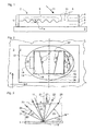
- FIG. 1 3 denotes a layer composite, 2 a security element, 3 a substrate, 4 a cover layer, 5 an impression layer, 6 a protective layer, 7 an adhesive layer, 8 a reflective interface, 9 an optically active structure and 10 a transparent location in the reflective interface 8.
- the composite layer 1 consists of several layers of different, successively applied to a carrier film not shown here plastic layers and comprises in the order typically the cover layer 4, the impression layer 5, the protective layer 6 and the adhesive layer 7.
- the cover layer 4 and the impression layer 5 are transparent to incident light 11. If the protective layer 6 and the adhesive layer 7 are also transparent, indicia (not shown here, attached to the surface of the substrate 3) can be seen through the transparent location 10.
- the common contact area between the impression layer 5 and the protective layer 6 is the interface 8.
- the optically active structures 9 having a structure height H St of an optically variable pattern are formed in the impression layer 5. Since the protective layer 6 fills the valleys of the optically active structures 9, the interface 8 has the shape of the optically active structures 9.
- the interface 8 is provided with a metal coating, preferably from the elements of Table 5 of the aforementioned US 4,856,857 , in particular aluminum, silver, gold, copper, chromium, tantalum, etc., which separates the impression layer 5 and the protective layer 6 as a reflection layer.
- the electrical conductivity of the metal coating causes a high reflectivity for visible incident light 11 at the interface 8.
- one or more layers of one of the known, transparent inorganic dielectrics are suitable instead of Metallbelags US 4,856,857 or the reflective layer has a multi-layered interference layer, such as a two-layered metal-dielectric combination or a metal-dielectric-metal combination.
- the reflection layer is structured in one embodiment, ie it covers the interface 8 only partially and in predetermined zones of the interface 8.
- the composite layer 1 is produced as a plastic laminate in the form of a long film web with a multiplicity of juxtaposed copies of the optically variable pattern.
- the security elements 2 are cut out of the film web and joined to a substrate 3 by means of the adhesive layer 7.
- the substrate 3 usually in the form of a document, a banknote, a bank card, a passport or other important or valuable object, is provided with the security element 2 in order to authenticate the authenticity of the object.
- FIG. 2 shows a section of the substrate 3 with the security element 2.
- cover layer 4 FIG. Fig. 1
- impression layer 5 Fig. 1
- the surface pattern 12 lies in a plane spanned by the coordinate axes x, y and contains a security feature 16 of at least one surface part 13, 14, 15 easily recognizable in the contour with the naked eye, ie the dimensions of the surface part are greater than in at least one direction 0.4 mm.
- the security feature 16 is in the drawing of FIG. 2 double framed for illustrative reasons.
- the optically active structures 9 such as microscopically fine diffractive gratings, microscopically fine, light-scattering relief structures or even mirror surfaces in the interface 8 (FIG. Fig. 1 ) molded.
- incident light 11 is reflected by the optically active structure 9 and deflected in a predetermined manner.
- the incident light 11 falls in the diffraction plane 20 which is perpendicular to the surface of the layer composite 1 with the security element 2 (FIG. Fig. 1 ) and contains a surface normal 21, on the optically active structure 9 in the composite layer 1 a.
- the incident light 11 is a parallel bundle of light rays and includes with the surface normal 21 the angle of incidence ⁇ .
- the optically effective structure 9 is one of the known grids, the grating deflects the incident light 11 into different diffraction orders 23 to 25 determined by the spatial frequency f of the grating, provided that the grating vector describing the grating lies in the diffraction plane 20 , The wavelengths ⁇ contained in the incident light 11 are deflected at the predetermined angles into the different diffraction orders 23 to 25.
- the polychromatic incident light 11 is fanned out due to the diffraction at the grating in the light rays of the different wavelengths ⁇ of the incident light 11, ie the visible part of the spectrum extends in the region between the violet light beam (arrow 26 and 27 and 28) and the red light beam (arrow 29 or 30 or 31) in each diffraction order 23, 24 and 25, respectively.
- the light diffracted into the zeroth diffraction order is the light 22 reflected by the angle of reflection ⁇ .
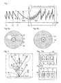
- FIG. 4 shows a in the surface elements 17 ( Fig. 2 ) until 19 ( Fig. 2 ) shaped diffraction grating 32, the microscopically fine relief profile R (x, y), for example, has a sinusoidal, periodic profile cross section of constant profile height h and with the spatial frequency f.
- the averaged relief of the diffraction grating 32 defines a central surface 33 arranged parallel to the cover layer 4.
- the parallel incident light 11 penetrates the cover layer 4 and the impression layer 5 and is applied to the optically effective structure 9 (FIG. Fig. 1 ) of the diffraction grating 32 deflected.
- the parallel diffracted light beams 34 of the wavelength ⁇ leave the security element 2 in the line of sight of an observer 35, who in the illumination of the surface pattern 12 (FIG. Fig. 2 ) with the parallel incident light 11, the colored, brightly radiating surface elements 17, 18, 19 sees.
- FIG. 5 lies the diffraction plane 20 in the plane of the drawing.
- a diffraction structure S (x, y) is formed, the central surface 33 of which is arched or inclined locally to the surface of the layer composite 1.
- the diffraction structure S (x, y) is a function of the coordinates x and y in the plane of the surface pattern 12 parallel to the surface of the layer composite 1 (FIG. Fig. 2 ), in which the surface parts 13, 14 ( Fig. 2 ), 15 lie.
- the relief profile R (x, y) generates the periodic diffraction grating 32 with the profile of one of the known sinusoidal, asymmetrical or symmetrical sawtooth or rectangular shapes.
- the microscopically fine relief profile R (x, y) of the diffraction structure S (x, y) is a matte structure instead of the periodic diffraction grating 32.
- the matte structure is a microscopically fine stochastic structure having a predetermined scattering characteristic for the incident light 11, wherein in an anisotropic matt structure instead of the grid vector, a preferred direction occurs.
- the matte structures scatter the perpendicularly incident light into a scattering cone having an aperture angle predetermined by the scattering power of the matte structure and the direction of the reflected light 22 as the cone axis.
- the intensity of the scattered light is e.g.
- the cross section of the scattering cone perpendicular to the cone axis is rotationally symmetric in a matt structure referred to here as "isotropic".
- the matte structure is here called "anisotropic".
- the profile height h ( Fig. 4 ) of the relief profile R (x, y) in the region of the overlay function M (x, y) is not changed, ie the relief profile R (x; y) follows the overlay function M (x, y).
- the uniquely defined superimposition function M (x, y) is at least piecewise differentiable and curved at least in partial areas, ie ⁇ M (x, y) ⁇ 0, periodic or aperiodic and is not a periodic triangular or rectangular function.
- the periodic superposition functions M (x, y) have a spatial frequency F of at most 20 lines / mm.
- links between two adjacent extreme values of the overlay functions M (x, y) are at least 0.025 mm long.
- the preferred values for the spatial frequency F are limited to at most 10 lines / mm and the preferred values for the distance between adjacent extreme values are at least 0.05 mm.
- the superimposition function M (x, y) thus varies as a macroscopic function in the continuous range slowly compared to the relief profile R (x, y).
- the superimposition function M (x, y) has a gradient 38, grad (M (x, y)) at each point P (x, y) on the sections lying parallel to the track 36 with continuous sections.
- the gradient 38 means the component of the degree (M (x, y)) in the diffraction plane 20, since the observer 35 defines the optically effective diffraction plane 20.
- the diffraction grating 32 has, in each point of the surface part 13, 14, 15, a gradient ⁇ predetermined by the gradient 38 of the superposition function M (x, y).
- the deformation of the central surface 33 causes a new, advantageous optical effect. This effect is explained by the diffraction behavior at transmission points A, B, C of the surface normal 21 and normal 21 ', 21 "to the central surface 33, eg along the track 36.
- the refraction of the incident light 11, the reflected light 22 and the diffracted light Light rays 34 at the boundary surfaces of the layer composite 1 is the sake of simplicity in the drawing of FIG. 5 not shown and not included in the following calculations.
- the inclination ⁇ is determined by the gradient 38.
- the normals 21 'and 21 ", the grating vector of the diffraction grating 32 ( Fig.
- the angle of incidence ⁇ ( Fig. 3 ), which are enclosed by the dashed lines 21, 21 ', 21 "and the white, parallel incident light 11.
- This also changes the wavelength ⁇ of the diffracted light beams 34 deflected in a predetermined viewing direction 39 to the observer 35. If the normal 21' tilted away by the viewer 35, the wavelength ⁇ of the diffracted light beams 34 is greater than when the normal 21 "to the observer 35 is tilted.
- the color bands of the spectrum can be seen by the observer 35 at a distance of 30 cm, at least 2 mm in length or more must be selected for the distance between the throughput points A and C.
- the surface of the surface part 13, 14, 15 has a faint gray.
- the angle of incidence ⁇ changes.
- the visible color bands of the spectra shift continuously in the region of the overlay function M (x, y) along the track 36.
- the color of the diffracted light beam 34 changes in the piercing point A ins Yellow-green, the color of the diffracted light beam 34 in the piercing point B to the blue and the color of the diffracted light beam 34 in the piercing point C in violet.
- the observer 35 perceives the change in the colors of the diffracted light 34 as migration of the color bands in a continuous manner over the surface part 13, 14, 15.
- the number of color bands of how many diffraction orders the observer sees on the surface part 13, 14, 15 simultaneously depends on the spatial frequency of the diffraction grating 32 and the number of periods and the amplitude of the superposition function M (x, y) within the surface part 13, 14, 15 from.
- the observer 35 sees in the direction of the reflected light 22 only a bright, white-gray band instead of the ribbons.
- the bright, whitish-gray band is visible to the observer 35 as a function of the scattering power of the matt structure, even if the color band is flat over the surface of the surface part 13, 14, 15 Viewing direction 39 is oblique to the diffraction plane 20.
- strip 40 ( Fig. 6a ) meant both the color bands of a diffraction order 23, 24, 25 and the bright white-gray band produced by the matt structure.
- Fig. 6a is the displacement of the strip from the observer 35 (FIG. Fig. 5 ) easier to recognize when a reference to the security feature 16 is present.
- a reference to the security feature 16 Serve as a reference on the surface portion 13, 14, 15, for example, on the central surface portion 14, arranged identification marks 37 ( Fig. 2 ) and / or a predetermined boundary shape of the surface part 13, 14, 15.
- the reference specifies a predetermined viewing condition, which is determined by tilting the layer composite 1 (FIG. Fig. 1 ) is adjustable so that the strip 40 is positioned predetermined against the reference.
- the optically active structure 9 (FIG. Fig. 1 ) of the interface 8 ( Fig.
- a light-absorbing imprint on the security feature 16 can also be used as a reference for the movement of the strip 40, or the identification mark 37 is produced by means of the structured reflection layer.
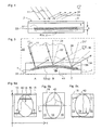
- the security feature 16 serve the adjacent on both sides of the central surface portion 14, adjacent surface portions 13 and 15 as a mutual reference.
- the adjacent surface parts 13 and 15 both have a diffraction structure S * (x, y).
- the security feature 16 along the coordinate axis y or the track 36 has a dimension of at least 5 mm, preferably more than 10 mm.
- the dimensions along the coordinate axis x are more than 0.25 mm, but preferably at least 1 mm.
- the oval surface part 14 has the diffraction structure S (y) dependent only on the coordinate y, while the surface parts 13 and 15 with the diffraction structure S * (y) dependent only on the coordinate y on both sides of the oval surface part 14 along the coordinate y extend.
- the gradient 38 ( Fig. 5 ) and the grating vector of the diffraction grating 32 (FIG. Fig. 4 ) or the preferred direction of the "anisotropic" matt structure are aligned substantially parallel or anti-parallel to the direction of the coordinate y.
- the azimuth ⁇ of the grating vector or the preferred direction of the matt structure is related to a gradient plane which is determined by the gradient 38 and the surface normal 21.
- the azimuth ⁇ is not limited to the said preferred values.
- the strip 40 is in the drawing of FIGS. 6a to 6c Narrow drawn to clearly show the movement effect.
- the width of the strips 40 in the direction of the unsigned arrows depends on the diffraction structure S (y). Particularly in the case of the color bands, the spectral color gradient extends over a larger part of the surface part 13, 14, 15, so that the movement of the strips 40 can be observed on the basis of the wandering of a detail in the visible spectrum, for example the red color band.
- FIG. 6b shows the security feature 16 after rotation about the tilting axis 41 in a predetermined tilt angle, below which the strips 40 of the two outer surface portions 13, 15 and the central surface portion 14 lie on a line parallel to the tilting axis 41.
- This predetermined tilt angle is determined by the choice of the overlay structure M (x, y).
- the security element 2 ( Fig. 2 ) is on the surface pattern 12 ( Fig. 2 ) to see a predetermined pattern only when in the security feature 16, the strip or strips 40 occupy a predetermined position, ie when the observer 35 views the security element 2 under the viewing conditions determined by the predetermined tilt angle.
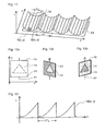
- FIG. 7 shows a cross section along the track 36 ( Fig. 2 ) through the layer composite 1, for example in the region of the surface part 14 (FIG. Fig. 2 ). So that the layer composite 1 is not too thick and thus difficult to manufacture or use, the structural height H St ( Fig. 1 ) of the diffraction structure S (x; y).
- the overlay function M (y) 0.5 • y 2 • K left of the coordinate axis z, in which the height of the layer composite 1 expands, shown in section alone.
- the superposition function M (y) on a discontinuity point at which on the side remote from the point P 0 the value of the overlay function M (y) is reduced by the value H to the height z 0 , that is in the diffraction structure
- the function C (x; y) is limited in terms of amount to a range of values, for example to half the value of the structure height H ST .
- the discontinuities of the function ⁇ M (x; y) + C (x; y) ⁇ modulo Hub H-C (x; y) generated for technical reasons are not to be counted as extreme values of the superposition function M (x; y).
- the values for the hub H may be locally smaller.
- the locally varying stroke H is determined by the distance between two consecutive points of discontinuity P n not exceeding a predetermined value in the range from 40 ⁇ m to 300 ⁇ m.
- the diffraction structure S (x, y) extends on both sides of the coordinate axis z and not only as in the drawing of FIG FIG. 7 is shown, to the right of the coordinate axis z.
- the structure height H St is the sum of the stroke H and the profile height h (FIG. Fig. 4 ) and equal to the value of the diffraction structure S (x, y) at point P (x; y).
- the structure height H St is advantageously less than 40 ⁇ m, preferred values of the structure height H St being ⁇ 5 ⁇ m.
- M x ⁇ y 0 . 5 • x 2 + y 2 • K .
- M x ⁇ y a • 1 + sin 2 ⁇ ⁇ F x • x • sin 2 ⁇ ⁇ F y • y .
- the overlay functions M (x, y) are periodically composed of a predetermined section of another function and have one or more periods along the track 36.
- the observer 35 detects in daylight according to the viewing direction 39 ( Fig. 5 ), a bright white-gray spot 42 against a dark gray background 43, wherein the position of the spot 42 in the surface part 14 with respect to the identification mark 37 and the contrast between the spot 42 and the background 43 are dependent on the viewing direction 39.
- the extent of the stain 42 is determined by the scattering power of the matte structure and the curvature of the superposition function M (x, y).
- the security element 2 ( Fig. 2 ) is, for example, by tilting about the tilting axis 41 (FIG. Fig. 5 ) and / or rotating about the surface normal 21 (FIG. Fig. 5 ) of the layer composite 1 ( Fig. 5 ) like in the FIG. 8b in such a way to align the predetermined viewing direction 39, that the spot 42 is located within the identification mark 37, which is arranged for example in the center of the circularly surrounded surface portion 14.
- the FIG. 9 shows the diffractive effect of the diffraction structure S (x, y) ( Fig. 7 ) in the diffraction plane 20.
- the relief structure R (x, y) ( Fig. 4 ) is the diffraction grating 32 (FIG. Fig. 4 ) with an eg sinusoidal profile and with a spatial frequency f less than 2400 lines / mm.
- the grating vector of the relief structure R (x, y) lies in the diffraction plane 20.
- first beams 44 having the wavelength ⁇ 1 with the incident light 11 include the viewing angle ⁇ and second beams 45 having the wavelength ⁇ 2 include the viewing angle - ⁇ .
- the observer 35 sees the surface portion 13, 14, 15 at the viewing angle ⁇ in the color with the wavelength ⁇ 1 .
- the observer 35 sees the surface part 13, 14, 15 at the viewing angle - ⁇ in the color of the wavelength ⁇ 2 .
- Equation (1) is easy to deduce for other atomic numbers m.
- the ordinal numbers m and the viewing angle ⁇ for a particular observable color are determined by the spatial frequency f.
- FIG. 10a and 10b is an example of an embodiment of the security feature 16, wherein in the FIG. 10a the security element 2 against the security element 2 in the FIG. 10b rotated in its plane by 180 °.
- the diffraction plane 20 ( Fig. 9 ) is shown with its track 36.
- a background field 46 adjoins at least one surface part 13, 14, 15 and has the diffraction grating 32 (FIG. Fig. 4 ) with the same relief profile R (x, y) and the background field 46 own Spatialfrequenz f.
- the grating vector of the relief profile R (x, y) is aligned parallel to the track 36 in the surface parts 13, 14, 15 and in the background field 46.
- white light 11 shine in the security feature 16 in the orientation of the FIG. 10a under the viewing angle + ⁇
- the surface parts 13, 14, 15 and the background field 46 in the same color
- the observer 35 (FIG. Fig. 5 ) the security feature 16 appears to illuminate without contrast in a uniform color, for example, the deflected first beams 44 (FIG. Fig. 9 ) the wavelength ⁇ 1 , eg 680 nm (red), on.
- the entire security feature 16 is observed under the viewing angle - ⁇ .
- the middle surface 33 (FIG. Fig. 9 ) of the diffraction grating 32 ( Fig. 4 ) the inclination ⁇ ( Fig.
- the advantage of this embodiment is the conspicuous optical behavior of the security feature 16, namely the color contrast visible under a single predetermined orientation of the security element 2 after a 180 ° rotation of the security element 2 around the surface normal 21 (FIG. Fig. 3 ) changes or disappears.
- the security feature 16 thus serves to define a predetermined orientation of the security element 2 with the non-holographically copied security feature 16.
- each surface part 13, 14, 15 has a section of the superimposition function M (x, y), so that the inclination ⁇ in the surface part 13, 14, 15 continuously changes in a predetermined direction and the wavelengths of the second rays 45 out an area on both sides of the wavelength ⁇ k originate.
- the similarly limited surface portions 13, 14, 15 form a plurality of arranged on the background field 46 surface portions 13, 14, 15 a logo, a lettering, etc.
- the eg rectangular surface part 13, 14 (FIG. Fig. 10 ), 15 ( Fig. 10 ) is aligned with its longitudinal side parallel to the coordinate x and divided into narrow sub-areas 47 of the width b, whose longitudinal sides are aligned parallel to the coordinate axis y.
- Each period 1 / F x of the overlay structure M (x; y) extends over a number t of the partial surfaces 47, eg the number t is in the value range from 5 to 10.
- the width b should not fall below 10 ⁇ m, since otherwise the diffraction structure S (x, y) is not defined enough on the partial surface 47.
- the diffraction structures S (x, y) of the adjacent sub-areas 47 differ in the summands, the relief profile R (x, y) and the section of the superimposition function M (x, y) assigned to the subarea 47.
- the relief profile R i (x, y) of the i-th partial surface 47 differs from the two relief profiles R i + 1 (x, y) and R i-1 (x, y) of the adjacent partial surfaces 47 by at least one lattice parameter, such as Azimuth, spatial frequency, profile h ( Fig. 4 ), etc. If the spatial frequency F x or F y is at most 10 lines / mm but not less than 2.5 lines / mm, the observer 35 (FIG. Fig.
- the relief profile R (x, y) changes continuously as a function of the phase angle of the periodic overlay function M (x, y).
- the in the FIG. 11 shown diffraction structures S (x, y) are in the embodiment of the in Figures 12 shown security feature 16 deployed, which unfolds a novel, optical effect in the illumination with white light 11 when the security feature 16 is tilted about the coordinate axis y parallel to the tilting axis 41.
- the security feature 16 comprises the triangular first surface part 14, which is arranged in the rectangular second surface part 13.
- the diffraction structure S (x, y) is characterized in that the spatial frequency f of the relief profile R (x, y) in the direction of the coordinate axis x within each period of the superposition function M (x, y) is gradual or continuous a predetermined Spatialfrequenz- area changed ⁇ f, wherein the spatial frequency f i in the ith subarea 47 ( Fig. 7 ) is greater than the spatial frequency f i-1 in the preceding (i-1) -th sub-area 47.
- the first sub-area 47 has the spatial frequency f with the value f A.
- the diffraction structure S (x, y) is characterized in that the spatial frequency f of the relief profile R (x, y) in the direction of the coordinate axis x within a period of the superimposition function M (x, y) of the one face 47 to the next stepwise or continuously reduced.
- the grating vectors and the track 36 (FIG. Fig. 11 ) of the diffraction plane 20 ( Fig. 9 ) are aligned in two surface portions 13, 14 substantially parallel to the tilting axis 41.
- the gradient 38 is substantially parallel to the plane spanned by the coordinate axes x and z.
- the security feature 16 lies in the x - y plane spanned by the coordinate axes x and y, the viewing direction 39 (FIG. Fig. 5 ) forms a right angle with the coordinate axis x.
- the partial areas 47 are illuminated in the region of the minima of the superposition function M (x, y). Since these partial surfaces 47 in both diffraction structures S (x, y), S ** (x, y) have the same relief profile R (x, y) and the same inclination ⁇ ⁇ 0 °, the two surface parts 13, 14 in the viewing direction 39 diffracted light beams 34 ( Fig.
- FIG. 12c is the security feature 1 of the in the FIG. 12a shown tilted position about the tilting axis 41 to the right. Even when tilting to the right, the color contrast is clear, but with reversed colors.
- the color of the first surface part 14 shifts in the direction of blue, since the partial surfaces 47 become effective, in which the spatial frequency f of the relief profile R (x, y) is greater than the value f M , while the color of the second surface part 13 in the direction Red shifts because the faces 47 ( Fig. 11 ), in which the spatial frequency f of the relief profile R (x, y) of the diffraction structure S ** (x, y) decreases with respect to the value f M.
- the relief profile R (x, y) in the sub-areas 47 of each period 1 / F x has the same spatial frequency f, but the relief profile R (x, y) differs from sub-area 47 to sub-area 47 by its azimuth angle ⁇ of the grid vector relative to the coordinate axis y.
- the azimuth angle ⁇ is dependent on the local inclination ⁇ ( Fig.
- the second surface part 13 (12a) in which the mirrored diffraction structure S ** (x, y) is formed is ejected only at a single predetermined tilt angle in the predetermined color, for example, in a mixed color generated from the green region. lights. At other angles of tilt, the second surface part 13 is dark gray.
- the overlay function M (x, y) employed in the diffraction structure S (x, y) is an asymmetric function in the coordinate axis x direction.
- the spatial frequency F x or F y is in the range of 2.5 lines / mm to and 10 lines / mm. Not shown are the points of discontinuity caused by Operation Modulo Hub H ( Fig. 7 ) arise.
- FIGS. 12a to 12c For example, instead of a single triangular first surface part 14 on the second surface part 13, a plurality of the first surface parts 14 may be arranged, which form a logo, a lettering, etc.
- relief images are also used as at least piecewise continuous superimposition function M (x, y) in the diffraction structure S (x, y), wherein advantageously the relief profile R (x, y) is an "isotropic" matte structure.
- the observer of the security element 2 in this embodiment receives the impression of a three-dimensional image with a characteristic surface structure. When rotating and tilting the security element 2, the brightness distribution in the image changes according to the expectation in a true relief image, but projecting elements do not cast a shadow.
- all diffraction structures S are in their structural height to the value H St ( Fig. 1 ), as indicated by the FIG. 7 was explained.
- the relief profiles R (x, y) and overlay functions M (x, y) used in the special embodiments described above can be combined as desired to form other diffraction structures S (x, y).
- the use of the security features 16 described above in the security element 2 has the advantage that the security feature 16 forms an effective barrier against attempts to holographically copy the security element 2.
- the positional shifts or color shifts on the surface of the security feature 16 can be recognized only in a modified form.
Landscapes
- Diffracting Gratings Or Hologram Optical Elements (AREA)
- Credit Cards Or The Like (AREA)
- Road Signs Or Road Markings (AREA)
- Burglar Alarm Systems (AREA)
- Memory System Of A Hierarchy Structure (AREA)
- Materials For Medical Uses (AREA)
- Developing Agents For Electrophotography (AREA)
Applications Claiming Priority (3)
| Application Number | Priority Date | Filing Date | Title |
|---|---|---|---|
| DE10216562 | 2002-04-05 | ||
| DE10216562A DE10216562C1 (de) | 2002-04-05 | 2002-04-05 | Sicherheitselement mit Mikro- und Makrostrukturen |
| PCT/EP2003/003482 WO2003084764A2 (de) | 2002-04-05 | 2003-04-03 | Sicherheitselement mit mikro- und makrostrukturen |
Publications (3)
| Publication Number | Publication Date |
|---|---|
| EP1492679A2 EP1492679A2 (de) | 2005-01-05 |
| EP1492679B1 EP1492679B1 (de) | 2010-11-10 |
| EP1492679B2 true EP1492679B2 (de) | 2014-06-25 |
Family
ID=28685061
Family Applications (1)
| Application Number | Title | Priority Date | Filing Date |
|---|---|---|---|
| EP03714917.6A Expired - Lifetime EP1492679B2 (de) | 2002-04-05 | 2003-04-03 | Sicherheitselement mit mikro- und makrostrukturen |
Country Status (11)
| Country | Link |
|---|---|
| US (1) | US7680274B2 (zh) |
| EP (1) | EP1492679B2 (zh) |
| JP (2) | JP2005528633A (zh) |
| CN (1) | CN100537267C (zh) |
| AT (1) | ATE487611T1 (zh) |
| AU (1) | AU2003219126A1 (zh) |
| DE (2) | DE10216562C1 (zh) |
| ES (1) | ES2356227T5 (zh) |
| PL (1) | PL206879B1 (zh) |
| RU (1) | RU2311304C2 (zh) |
| WO (1) | WO2003084764A2 (zh) |
Families Citing this family (24)
| Publication number | Priority date | Publication date | Assignee | Title |
|---|---|---|---|---|
| DE10318105B4 (de) * | 2003-03-21 | 2007-09-20 | Ovd Kinegram Ag | Verfahren zur Herstellung von Mikrostrukturen |
| ATE371200T1 (de) | 2003-03-21 | 2007-09-15 | Ovd Kinegram Ag | Verfahren zur herstellung von zwei überlagernden mikrostrukturen |
| DE102004003340A1 (de) * | 2004-01-22 | 2005-08-18 | Fraunhofer-Gesellschaft zur Förderung der angewandten Forschung e.V. | Flächensubstrat mit einer Makro- und Mikrostrukturen aufweisenden Substratoberfläche sowie Verfahren zur Herstellung eines derartigen Flächensubstrates |
| BRPI0513694A (pt) * | 2004-07-21 | 2008-05-13 | Rolic Ag | dispositivos ópticos anisotrópicos e método para produção do mesmo |
| DE102005006231B4 (de) * | 2005-02-10 | 2007-09-20 | Ovd Kinegram Ag | Verfahren zur Herstellung eines Mehrschichtkörpers |
| DE102005017169B4 (de) | 2005-04-13 | 2023-06-22 | Ovd Kinegram Ag | Transferfolie |
| DE102005017170B4 (de) * | 2005-04-13 | 2010-07-01 | Ovd Kinegram Ag | Transferfolie, Verfahren zu deren Herstellung sowie Mehrschichtkörper und dessen Verwendung |
| RU2443004C2 (ru) † | 2006-05-02 | 2012-02-20 | Холограм Индастрис | Защитный маркировочный оптический элемент, способ изготовления такого элемента, система, содержащая такой элемент, и считывающее устройство для проверки такого элемента |
| US8133638B2 (en) * | 2006-05-30 | 2012-03-13 | Brady Worldwide, Inc. | All-polymer grating microstructure |
| EP1889732A1 (en) * | 2006-08-18 | 2008-02-20 | Setec Oy | Method of superimposing an image onto another, method of personalizing a data carrier using the the method |
| CA2708526C (en) | 2008-04-18 | 2012-02-21 | Toppan Printing Co., Ltd. | Display and labeled article |
| DE102008028187A1 (de) * | 2008-06-12 | 2009-12-17 | Giesecke & Devrient Gmbh | Sicherheitselement mit optisch variablem Element. |
| JP5470794B2 (ja) * | 2008-09-30 | 2014-04-16 | 凸版印刷株式会社 | 表示体、粘着ラベル、転写箔及びラベル付き物品 |
| FR2959830B1 (fr) | 2010-05-07 | 2013-05-17 | Hologram Ind | Composant optique d'authentification et procede de fabrication dudit composant |
| EA017829B1 (ru) * | 2011-09-26 | 2013-03-29 | Общество С Ограниченной Ответственностью "Центр Компьютерной Голографии" | Микрооптическая система для визуального контроля аутентичности изделий |
| EA018164B1 (ru) * | 2011-09-26 | 2013-05-30 | Общество С Ограниченной Ответственностью "Центр Компьютерной Голографии" | Микрооптическая система формирования изображений для визуального контроля подлинности изделий |
| DE102012015900A1 (de) | 2012-08-10 | 2014-03-06 | Giesecke & Devrient Gmbh | Sicherheitselement mit farbeffekterzeugendem Gitter |
| EP2974879B1 (en) | 2013-03-12 | 2018-09-05 | Toppan Printing Co., Ltd. | Display body |
| DE102013105246B4 (de) * | 2013-05-22 | 2017-03-23 | Leonhard Kurz Stiftung & Co. Kg | Optisch variables Element |
| RU2544772C1 (ru) * | 2014-04-07 | 2015-03-20 | федеральное государственное бюджетное образовательное учреждение высшего профессионального образования "Московский государственный университет печати имени Ивана Федорова" (МГУП имени Ивана Федорова) | Способ контроля подлинности многоцветной печатной продукции |
| CN105403947A (zh) * | 2015-12-29 | 2016-03-16 | 上海宏盾防伪材料有限公司 | 一种具有全息图像的安全层结构 |
| GB2572745B (en) | 2018-03-22 | 2021-06-09 | De La Rue Int Ltd | Security elements and methods of manufacture thereof |
| JP7159631B2 (ja) * | 2018-06-14 | 2022-10-25 | 大日本印刷株式会社 | 情報記録媒体 |
| FR3121629B1 (fr) * | 2021-04-09 | 2023-04-07 | Surys | Composants optiques de sécurité visibles en réflexion, fabrication de tels composants et documents sécurisés équipé de tels composants |
Citations (4)
| Publication number | Priority date | Publication date | Assignee | Title |
|---|---|---|---|---|
| DE2701176B1 (de) † | 1976-12-21 | 1977-12-08 | Landis & Gyr Ag | Dokument und verfahren zu seiner herstellung |
| JPS6366300U (zh) † | 1986-10-22 | 1988-05-02 | ||
| WO2000061386A1 (de) † | 1999-04-09 | 2000-10-19 | Ovd Kinegram Ag | Dekorationsfolie |
| WO2003043832A1 (de) † | 2001-11-23 | 2003-05-30 | Ovd Kinegram Ag | Sicherheitselement mit beugungsstrukturen |
Family Cites Families (28)
| Publication number | Priority date | Publication date | Assignee | Title |
|---|---|---|---|---|
| CH659433A5 (de) | 1982-10-04 | 1987-01-30 | Landis & Gyr Ag | Dokument mit einem beugungsoptischen sicherheitselement. |
| JPS5988780A (ja) | 1982-11-08 | 1984-05-22 | アメリカン・バンク・ノ−ト・カムパニ− | 光回折記録体及び光回折パタ−ンを作る方法 |
| DE3650027T2 (de) | 1985-05-07 | 1995-01-26 | Dainippon Printing Co Ltd | Artikel mit transparentem Hologramm. |
| WO1988005387A1 (en) | 1987-01-13 | 1988-07-28 | Mancuso Robert J | Variable color print and method of making same |
| DE3717289A1 (de) | 1987-05-22 | 1988-12-01 | Karlsruhe Wiederaufarbeit | Behaelter zur aufnahme von feststoffhaltigen suspensionen |
| JPH0439040Y2 (zh) * | 1987-06-22 | 1992-09-11 | ||
| US4874213A (en) * | 1987-08-10 | 1989-10-17 | Polaroid Corporation | Method of forming volume phase reflection holograms |
| ATE69407T1 (de) * | 1988-03-03 | 1991-11-15 | Landis & Gyr Betriebs Ag | Dokument. |
| US5161057A (en) | 1988-09-12 | 1992-11-03 | Johnson Kenneth C | Dispersion-compensated fresnel lens |
| ATE98795T1 (de) | 1988-09-30 | 1994-01-15 | Landis & Gyr Business Support | Beugungselement. |
| EP0429782B1 (de) | 1989-12-01 | 1994-05-18 | Landis & Gyr Technology Innovation AG | Anordnung zur Verbesserung der Fälschungssicherheit eines Wertdokumentes |
| JP2543180Y2 (ja) * | 1991-11-05 | 1997-08-06 | 帝人株式会社 | パウチフイルム |
| US5561558A (en) | 1993-10-18 | 1996-10-01 | Matsushita Electric Industrial Co., Ltd. | Diffractive optical device |
| JP3392500B2 (ja) | 1994-02-28 | 2003-03-31 | 凸版印刷株式会社 | 回折格子パターンを有するディスプレイ |
| FR2726660B1 (fr) | 1994-11-03 | 1997-01-10 | Bernard Sermage | Reseau reflechissant de diffraction optique et procedes de fabrication |
| JP3556324B2 (ja) | 1995-06-16 | 2004-08-18 | 凸版印刷株式会社 | ホログラム検査装置及び方法 |
| US6130777A (en) | 1996-05-16 | 2000-10-10 | Dai Nippon Printing Co., Ltd. | Lenticular lens sheet with both a base sheet having lenticular elements and a surface diffusing part having elements of elementary shape smaller than lenticular elements |
| US6060143A (en) * | 1996-11-14 | 2000-05-09 | Ovd Kinegram Ag | Optical information carrier |
| WO1998026373A1 (de) | 1996-12-12 | 1998-06-18 | Landis & Gyr Technology Innovation Ag | Flächenmuster |
| JPH11160509A (ja) * | 1997-11-27 | 1999-06-18 | Toppan Printing Co Ltd | 回折格子パターンを有するディスプレイ |
| CH693427A5 (de) | 1998-01-27 | 2003-07-31 | Ovd Kinegram Ag | Flächenmuster. |
| JPH11224050A (ja) * | 1998-02-05 | 1999-08-17 | Toppan Printing Co Ltd | 偽造防止媒体、シール及び転写箔 |
| US6324004B1 (en) * | 1999-01-21 | 2001-11-27 | Ovd Kingegram Ag | Planar patterns with superimposed diffraction gratings |
| DE10028426A1 (de) * | 1999-06-10 | 2001-04-12 | Fraunhofer Ges Forschung | Verfahren zur Herstellung einer dreidimensionalen Struktur |
| DE19963849A1 (de) * | 1999-12-30 | 2001-07-12 | Giesecke & Devrient Gmbh | Datenträger mit gedrucktem Sicherheitselement |
| RU2250500C2 (ru) * | 2000-04-15 | 2005-04-20 | Овд Кинеграм Аг | Элемент наборного орнамента |
| GB0015873D0 (en) * | 2000-06-28 | 2000-08-23 | Rue De Int Ltd | Optically variable security device |
| DE10216561B4 (de) | 2002-04-05 | 2010-01-07 | Ovd Kinegram Ag | Sicherheitselement mit Makrostrukturen |
-
2002
- 2002-04-05 DE DE10216562A patent/DE10216562C1/de not_active Expired - Lifetime
-
2003
- 2003-04-03 ES ES03714917.6T patent/ES2356227T5/es not_active Expired - Lifetime
- 2003-04-03 AU AU2003219126A patent/AU2003219126A1/en not_active Abandoned
- 2003-04-03 PL PL371208A patent/PL206879B1/pl unknown
- 2003-04-03 AT AT03714917T patent/ATE487611T1/de active
- 2003-04-03 JP JP2003581986A patent/JP2005528633A/ja active Pending
- 2003-04-03 EP EP03714917.6A patent/EP1492679B2/de not_active Expired - Lifetime
- 2003-04-03 WO PCT/EP2003/003482 patent/WO2003084764A2/de active Application Filing
- 2003-04-03 RU RU2004132228/12A patent/RU2311304C2/ru not_active IP Right Cessation
- 2003-04-03 CN CNB038079321A patent/CN100537267C/zh not_active Expired - Fee Related
- 2003-04-03 DE DE50313255T patent/DE50313255D1/de not_active Expired - Lifetime
- 2003-04-03 US US10/510,395 patent/US7680274B2/en not_active Expired - Fee Related
-
2010
- 2010-07-16 JP JP2010161408A patent/JP5695357B2/ja not_active Expired - Fee Related
Patent Citations (4)
| Publication number | Priority date | Publication date | Assignee | Title |
|---|---|---|---|---|
| DE2701176B1 (de) † | 1976-12-21 | 1977-12-08 | Landis & Gyr Ag | Dokument und verfahren zu seiner herstellung |
| JPS6366300U (zh) † | 1986-10-22 | 1988-05-02 | ||
| WO2000061386A1 (de) † | 1999-04-09 | 2000-10-19 | Ovd Kinegram Ag | Dekorationsfolie |
| WO2003043832A1 (de) † | 2001-11-23 | 2003-05-30 | Ovd Kinegram Ag | Sicherheitselement mit beugungsstrukturen |
Also Published As
| Publication number | Publication date |
|---|---|
| ES2356227T3 (es) | 2011-04-06 |
| RU2004132228A (ru) | 2005-04-10 |
| WO2003084764A3 (de) | 2004-02-05 |
| DE50313255D1 (de) | 2010-12-23 |
| JP2011008273A (ja) | 2011-01-13 |
| JP5695357B2 (ja) | 2015-04-01 |
| ES2356227T5 (es) | 2014-10-10 |
| JP2005528633A (ja) | 2005-09-22 |
| CN100537267C (zh) | 2009-09-09 |
| US7680274B2 (en) | 2010-03-16 |
| PL371208A1 (en) | 2005-06-13 |
| RU2311304C2 (ru) | 2007-11-27 |
| EP1492679A2 (de) | 2005-01-05 |
| AU2003219126A8 (en) | 2003-10-20 |
| US20050082819A1 (en) | 2005-04-21 |
| WO2003084764A2 (de) | 2003-10-16 |
| EP1492679B1 (de) | 2010-11-10 |
| CN1646331A (zh) | 2005-07-27 |
| AU2003219126A1 (en) | 2003-10-20 |
| ATE487611T1 (de) | 2010-11-15 |
| PL206879B1 (pl) | 2010-09-30 |
| DE10216562C1 (de) | 2003-12-11 |
Similar Documents
| Publication | Publication Date | Title |
|---|---|---|
| EP1492679B2 (de) | Sicherheitselement mit mikro- und makrostrukturen | |
| DE3206062C2 (zh) | ||
| EP1458578B1 (de) | Diffraktives sicherheitselement | |
| EP1275084B1 (de) | Flächenmuster | |
| EP1446294B1 (de) | Sicherheitselement mit beugungsstrukturen | |
| EP2632739B1 (de) | Sicherheitselement mit optisch variablem flächenmuster | |
| DE102008046128B4 (de) | Optisch variables Sicherheitselement mit Mattbereich | |
| EP1492678B1 (de) | Sicherheitselement mit makrostrukturen | |
| DE102004044458A1 (de) | Sicherheitsdokument | |
| DE112016000297T5 (de) | Anzeigekörper und Artikel | |
| DE10328760A1 (de) | Optisches Sicherheitselement | |
| WO1998026373A1 (de) | Flächenmuster | |
| EP1051647B1 (de) | Flächenmuster | |
| EP2126615B1 (de) | Gitterbild | |
| EP2853411B1 (de) | Sicherheitselement mit Linsenrasterbild | |
| EP2874820B1 (de) | Sicherheitselement für sicherheitspapiere, wertdokumente oder dergleichen | |
| DE102004003984A1 (de) | Gitterbild mit einem oder mehreren Gitterfeldern | |
| EP2889152A1 (de) | Sicherheitselement zur Darstellung zumindest einer optisch variablen Information | |
| WO2016110493A1 (de) | Verfahren zur herstellung von sicherheitselementen sowie sicherheitselemente | |
| EP2029371B1 (de) | Refraktives durchsichtssicherheitselement | |
| DE10216563B4 (de) | Sicherheitselement als Photokopierschutz | |
| DE102017106433A1 (de) | Sicherheitselement und Verfahren zur Herstellung eines Sicherheitselements | |
| EP3648983B1 (de) | Optisch variable sicherheitsanordnung |
Legal Events
| Date | Code | Title | Description |
|---|---|---|---|
| PUAI | Public reference made under article 153(3) epc to a published international application that has entered the european phase |
Free format text: ORIGINAL CODE: 0009012 |
|
| 17P | Request for examination filed |
Effective date: 20040910 |
|
| AK | Designated contracting states |
Kind code of ref document: A2 Designated state(s): AT BE BG CH CY CZ DE DK EE ES FI FR GB GR HU IE IT LI LU MC NL PT RO SE SI SK TR |
|
| AX | Request for extension of the european patent |
Extension state: AL LT LV MK |
|
| GRAP | Despatch of communication of intention to grant a patent |
Free format text: ORIGINAL CODE: EPIDOSNIGR1 |
|
| GRAS | Grant fee paid |
Free format text: ORIGINAL CODE: EPIDOSNIGR3 |
|
| GRAA | (expected) grant |
Free format text: ORIGINAL CODE: 0009210 |
|
| AK | Designated contracting states |
Kind code of ref document: B1 Designated state(s): AT BE BG CH CY CZ DE DK EE ES FI FR GB GR HU IE IT LI LU MC NL PT RO SE SI SK TR |
|
| REG | Reference to a national code |
Ref country code: GB Ref legal event code: FG4D Free format text: NOT ENGLISH |
|
| REG | Reference to a national code |
Ref country code: CH Ref legal event code: EP Ref country code: CH Ref legal event code: NV Representative=s name: FIAMMENGHI-FIAMMENGHI |
|
| REG | Reference to a national code |
Ref country code: IE Ref legal event code: FG4D Free format text: LANGUAGE OF EP DOCUMENT: GERMAN |
|
| REF | Corresponds to: |
Ref document number: 50313255 Country of ref document: DE Date of ref document: 20101223 Kind code of ref document: P |
|
| REG | Reference to a national code |
Ref country code: NL Ref legal event code: T3 |
|
| REG | Reference to a national code |
Ref country code: SE Ref legal event code: TRGR |
|
| REG | Reference to a national code |
Ref country code: ES Ref legal event code: FG2A Ref document number: 2356227 Country of ref document: ES Kind code of ref document: T3 Effective date: 20110406 |
|
| PG25 | Lapsed in a contracting state [announced via postgrant information from national office to epo] |
Ref country code: PT Free format text: LAPSE BECAUSE OF FAILURE TO SUBMIT A TRANSLATION OF THE DESCRIPTION OR TO PAY THE FEE WITHIN THE PRESCRIBED TIME-LIMIT Effective date: 20110310 Ref country code: CY Free format text: LAPSE BECAUSE OF FAILURE TO SUBMIT A TRANSLATION OF THE DESCRIPTION OR TO PAY THE FEE WITHIN THE PRESCRIBED TIME-LIMIT Effective date: 20101110 Ref country code: SI Free format text: LAPSE BECAUSE OF FAILURE TO SUBMIT A TRANSLATION OF THE DESCRIPTION OR TO PAY THE FEE WITHIN THE PRESCRIBED TIME-LIMIT Effective date: 20101110 |
|
| REG | Reference to a national code |
Ref country code: IE Ref legal event code: FD4D |
|
| PG25 | Lapsed in a contracting state [announced via postgrant information from national office to epo] |
Ref country code: GR Free format text: LAPSE BECAUSE OF FAILURE TO SUBMIT A TRANSLATION OF THE DESCRIPTION OR TO PAY THE FEE WITHIN THE PRESCRIBED TIME-LIMIT Effective date: 20110211 |
|
| PG25 | Lapsed in a contracting state [announced via postgrant information from national office to epo] |
Ref country code: IE Free format text: LAPSE BECAUSE OF FAILURE TO SUBMIT A TRANSLATION OF THE DESCRIPTION OR TO PAY THE FEE WITHIN THE PRESCRIBED TIME-LIMIT Effective date: 20101110 Ref country code: EE Free format text: LAPSE BECAUSE OF FAILURE TO SUBMIT A TRANSLATION OF THE DESCRIPTION OR TO PAY THE FEE WITHIN THE PRESCRIBED TIME-LIMIT Effective date: 20101110 |
|
| PLBI | Opposition filed |
Free format text: ORIGINAL CODE: 0009260 |
|
| PG25 | Lapsed in a contracting state [announced via postgrant information from national office to epo] |
Ref country code: DK Free format text: LAPSE BECAUSE OF FAILURE TO SUBMIT A TRANSLATION OF THE DESCRIPTION OR TO PAY THE FEE WITHIN THE PRESCRIBED TIME-LIMIT Effective date: 20101110 Ref country code: SK Free format text: LAPSE BECAUSE OF FAILURE TO SUBMIT A TRANSLATION OF THE DESCRIPTION OR TO PAY THE FEE WITHIN THE PRESCRIBED TIME-LIMIT Effective date: 20101110 Ref country code: RO Free format text: LAPSE BECAUSE OF FAILURE TO SUBMIT A TRANSLATION OF THE DESCRIPTION OR TO PAY THE FEE WITHIN THE PRESCRIBED TIME-LIMIT Effective date: 20101110 |
|
| PLAX | Notice of opposition and request to file observation + time limit sent |
Free format text: ORIGINAL CODE: EPIDOSNOBS2 |
|
| 26 | Opposition filed |
Opponent name: GIESECKE & DEVRIENT GMBH Effective date: 20110810 |
|
| BERE | Be: lapsed |
Owner name: OVD KINEGRAM A.G. Effective date: 20110430 |
|
| REG | Reference to a national code |
Ref country code: DE Ref legal event code: R026 Ref document number: 50313255 Country of ref document: DE Effective date: 20110810 |
|
| PG25 | Lapsed in a contracting state [announced via postgrant information from national office to epo] |
Ref country code: MC Free format text: LAPSE BECAUSE OF NON-PAYMENT OF DUE FEES Effective date: 20110430 |
|
| PLAF | Information modified related to communication of a notice of opposition and request to file observations + time limit |
Free format text: ORIGINAL CODE: EPIDOSCOBS2 |
|
| PG25 | Lapsed in a contracting state [announced via postgrant information from national office to epo] |
Ref country code: BE Free format text: LAPSE BECAUSE OF NON-PAYMENT OF DUE FEES Effective date: 20110430 |
|
| PLBB | Reply of patent proprietor to notice(s) of opposition received |
Free format text: ORIGINAL CODE: EPIDOSNOBS3 |
|
| PG25 | Lapsed in a contracting state [announced via postgrant information from national office to epo] |
Ref country code: LU Free format text: LAPSE BECAUSE OF NON-PAYMENT OF DUE FEES Effective date: 20110403 |
|
| PG25 | Lapsed in a contracting state [announced via postgrant information from national office to epo] |
Ref country code: HU Free format text: LAPSE BECAUSE OF FAILURE TO SUBMIT A TRANSLATION OF THE DESCRIPTION OR TO PAY THE FEE WITHIN THE PRESCRIBED TIME-LIMIT Effective date: 20101110 |
|
| PUAH | Patent maintained in amended form |
Free format text: ORIGINAL CODE: 0009272 |
|
| STAA | Information on the status of an ep patent application or granted ep patent |
Free format text: STATUS: PATENT MAINTAINED AS AMENDED |
|
| 27A | Patent maintained in amended form |
Effective date: 20140625 |
|
| AK | Designated contracting states |
Kind code of ref document: B2 Designated state(s): AT BE BG CH CY CZ DE DK EE ES FI FR GB GR HU IE IT LI LU MC NL PT RO SE SI SK TR |
|
| REG | Reference to a national code |
Ref country code: DE Ref legal event code: R102 Ref document number: 50313255 Country of ref document: DE |
|
| RIC2 | Information provided on ipc code assigned after grant |
Ipc: B42D 15/00 20060101AFI20140522BHEP |
|
| REG | Reference to a national code |
Ref country code: CH Ref legal event code: AELC |
|
| REG | Reference to a national code |
Ref country code: DE Ref legal event code: R102 Ref document number: 50313255 Country of ref document: DE Effective date: 20140625 |
|
| REG | Reference to a national code |
Ref country code: SE Ref legal event code: RPEO |
|
| REG | Reference to a national code |
Ref country code: ES Ref legal event code: DC2A Ref document number: 2356227 Country of ref document: ES Kind code of ref document: T5 Effective date: 20141010 |
|
| REG | Reference to a national code |
Ref country code: NL Ref legal event code: T3 |
|
| REG | Reference to a national code |
Ref country code: FR Ref legal event code: PLFP Year of fee payment: 14 |
|
| REG | Reference to a national code |
Ref country code: FR Ref legal event code: PLFP Year of fee payment: 15 |
|
| REG | Reference to a national code |
Ref country code: FR Ref legal event code: PLFP Year of fee payment: 16 |
|
| PGFP | Annual fee paid to national office [announced via postgrant information from national office to epo] |
Ref country code: SE Payment date: 20180424 Year of fee payment: 16 |
|
| REG | Reference to a national code |
Ref country code: SE Ref legal event code: EUG |
|
| PG25 | Lapsed in a contracting state [announced via postgrant information from national office to epo] |
Ref country code: SE Free format text: LAPSE BECAUSE OF NON-PAYMENT OF DUE FEES Effective date: 20190404 |
|
| PGFP | Annual fee paid to national office [announced via postgrant information from national office to epo] |
Ref country code: ES Payment date: 20200516 Year of fee payment: 18 Ref country code: FI Payment date: 20200417 Year of fee payment: 18 Ref country code: NL Payment date: 20200420 Year of fee payment: 18 Ref country code: CH Payment date: 20200423 Year of fee payment: 18 |
|
| PGFP | Annual fee paid to national office [announced via postgrant information from national office to epo] |
Ref country code: CZ Payment date: 20210324 Year of fee payment: 19 |
|
| PGFP | Annual fee paid to national office [announced via postgrant information from national office to epo] |
Ref country code: TR Payment date: 20210325 Year of fee payment: 19 |
|
| PGFP | Annual fee paid to national office [announced via postgrant information from national office to epo] |
Ref country code: IT Payment date: 20210430 Year of fee payment: 19 |
|
| PGFP | Annual fee paid to national office [announced via postgrant information from national office to epo] |
Ref country code: AT Payment date: 20210420 Year of fee payment: 19 Ref country code: GB Payment date: 20210422 Year of fee payment: 19 Ref country code: BG Payment date: 20210505 Year of fee payment: 19 |
|
| REG | Reference to a national code |
Ref country code: FI Ref legal event code: MAE |
|
| REG | Reference to a national code |
Ref country code: NL Ref legal event code: MM Effective date: 20210501 |
|
| PG25 | Lapsed in a contracting state [announced via postgrant information from national office to epo] |
Ref country code: LI Free format text: LAPSE BECAUSE OF NON-PAYMENT OF DUE FEES Effective date: 20210430 Ref country code: CH Free format text: LAPSE BECAUSE OF NON-PAYMENT OF DUE FEES Effective date: 20210430 Ref country code: FI Free format text: LAPSE BECAUSE OF NON-PAYMENT OF DUE FEES Effective date: 20210403 |
|
| PG25 | Lapsed in a contracting state [announced via postgrant information from national office to epo] |
Ref country code: NL Free format text: LAPSE BECAUSE OF NON-PAYMENT OF DUE FEES Effective date: 20210501 |
|
| REG | Reference to a national code |
Ref country code: ES Ref legal event code: FD2A Effective date: 20220629 |
|
| PG25 | Lapsed in a contracting state [announced via postgrant information from national office to epo] |
Ref country code: ES Free format text: LAPSE BECAUSE OF NON-PAYMENT OF DUE FEES Effective date: 20210404 |
|
| PGFP | Annual fee paid to national office [announced via postgrant information from national office to epo] |
Ref country code: DE Payment date: 20220331 Year of fee payment: 20 Ref country code: FR Payment date: 20220420 Year of fee payment: 20 |
|
| PG25 | Lapsed in a contracting state [announced via postgrant information from national office to epo] |
Ref country code: CZ Free format text: LAPSE BECAUSE OF NON-PAYMENT OF DUE FEES Effective date: 20220403 |
|
| REG | Reference to a national code |
Ref country code: AT Ref legal event code: MM01 Ref document number: 487611 Country of ref document: AT Kind code of ref document: T Effective date: 20220403 |
|
| GBPC | Gb: european patent ceased through non-payment of renewal fee |
Effective date: 20220403 |
|
| PG25 | Lapsed in a contracting state [announced via postgrant information from national office to epo] |
Ref country code: GB Free format text: LAPSE BECAUSE OF NON-PAYMENT OF DUE FEES Effective date: 20220403 Ref country code: AT Free format text: LAPSE BECAUSE OF NON-PAYMENT OF DUE FEES Effective date: 20220403 |
|
| REG | Reference to a national code |
Ref country code: DE Ref legal event code: R071 Ref document number: 50313255 Country of ref document: DE |
|
| PG25 | Lapsed in a contracting state [announced via postgrant information from national office to epo] |
Ref country code: IT Free format text: LAPSE BECAUSE OF NON-PAYMENT OF DUE FEES Effective date: 20220403 |