EP1492679B2 - Security element comprising micro- and macrostructures - Google Patents
Security element comprising micro- and macrostructures Download PDFInfo
- Publication number
- EP1492679B2 EP1492679B2 EP03714917.6A EP03714917A EP1492679B2 EP 1492679 B2 EP1492679 B2 EP 1492679B2 EP 03714917 A EP03714917 A EP 03714917A EP 1492679 B2 EP1492679 B2 EP 1492679B2
- Authority
- EP
- European Patent Office
- Prior art keywords
- security element
- function
- diffraction structure
- relief profile
- diffraction
- Prior art date
- Legal status (The legal status is an assumption and is not a legal conclusion. Google has not performed a legal analysis and makes no representation as to the accuracy of the status listed.)
- Expired - Lifetime
Links
Images
Classifications
-
- B—PERFORMING OPERATIONS; TRANSPORTING
- B42—BOOKBINDING; ALBUMS; FILES; SPECIAL PRINTED MATTER
- B42D—BOOKS; BOOK COVERS; LOOSE LEAVES; PRINTED MATTER CHARACTERISED BY IDENTIFICATION OR SECURITY FEATURES; PRINTED MATTER OF SPECIAL FORMAT OR STYLE NOT OTHERWISE PROVIDED FOR; DEVICES FOR USE THEREWITH AND NOT OTHERWISE PROVIDED FOR; MOVABLE-STRIP WRITING OR READING APPARATUS
- B42D25/00—Information-bearing cards or sheet-like structures characterised by identification or security features; Manufacture thereof
- B42D25/30—Identification or security features, e.g. for preventing forgery
- B42D25/328—Diffraction gratings; Holograms
Definitions
- the invention relates to a security element according to the preamble of claim 1.
- Such security elements consist of a thin composite layer of plastic, wherein at least relief structures from the group of diffraction structures, light-scattering structures and planar mirror surfaces are embedded in the layer composite.
- the cut from the thin layer composite security elements are glued to objects to authenticate the authenticity of the objects.
- the structure of the thin layer composite and the materials used for this purpose are, for example, in US 4,856,857 described. From the GB 2 129 739 A is also known to apply the thin layer composite with the aid of a carrier film on the object.
- An arrangement of the type mentioned is from the EP 0 429 782 B1 known.
- the glued on a document security element has a example of the EP 0 105 099 A1 known, optically variable surface pattern of mosaic-like arranged surface parts with known diffraction structures. So that a forged document can not be provided with a counterfeit document cut out of a genuine document or detached from a genuine document in order to simulate an apparent authenticity, security profiles are embossed in the security element and in adjacent parts of the document.
- the real document is distinguished by the security profiles that extend seamlessly from the security element to adjacent parts of the document. The impressing of the security profiles interferes with the recognition of the optically variable area pattern. In particular, the position of the die on the security element varies from copy to copy of the document.
- the WO 01/80175 A1 describes a diffractive surface pattern formed as a visible mosaic composed of surface parts in a laminate of plastic. At least in one surface part, a "zero order microstructure" with a modulated lattice profile is formed whose spatial frequency f multiplied by a predetermined cutoff wavelength of the visible spectrum yields a product greater than or equal to one.
- the invention has for its object to provide a cost-effective, novel security element, which has a high resistance to counterfeiting attempts, e.g. by means of a holographic copying method.
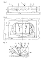
- FIG. 1 3 denotes a layer composite, 2 a security element, 3 a substrate, 4 a cover layer, 5 an impression layer, 6 a protective layer, 7 an adhesive layer, 8 a reflective interface, 9 an optically active structure and 10 a transparent location in the reflective interface 8.
- the composite layer 1 consists of several layers of different, successively applied to a carrier film not shown here plastic layers and comprises in the order typically the cover layer 4, the impression layer 5, the protective layer 6 and the adhesive layer 7.
- the cover layer 4 and the impression layer 5 are transparent to incident light 11. If the protective layer 6 and the adhesive layer 7 are also transparent, indicia (not shown here, attached to the surface of the substrate 3) can be seen through the transparent location 10.
- the common contact area between the impression layer 5 and the protective layer 6 is the interface 8.
- the optically active structures 9 having a structure height H St of an optically variable pattern are formed in the impression layer 5. Since the protective layer 6 fills the valleys of the optically active structures 9, the interface 8 has the shape of the optically active structures 9.
- the interface 8 is provided with a metal coating, preferably from the elements of Table 5 of the aforementioned US 4,856,857 , in particular aluminum, silver, gold, copper, chromium, tantalum, etc., which separates the impression layer 5 and the protective layer 6 as a reflection layer.
- the electrical conductivity of the metal coating causes a high reflectivity for visible incident light 11 at the interface 8.
- one or more layers of one of the known, transparent inorganic dielectrics are suitable instead of Metallbelags US 4,856,857 or the reflective layer has a multi-layered interference layer, such as a two-layered metal-dielectric combination or a metal-dielectric-metal combination.
- the reflection layer is structured in one embodiment, ie it covers the interface 8 only partially and in predetermined zones of the interface 8.
- the composite layer 1 is produced as a plastic laminate in the form of a long film web with a multiplicity of juxtaposed copies of the optically variable pattern.
- the security elements 2 are cut out of the film web and joined to a substrate 3 by means of the adhesive layer 7.
- the substrate 3 usually in the form of a document, a banknote, a bank card, a passport or other important or valuable object, is provided with the security element 2 in order to authenticate the authenticity of the object.
- FIG. 2 shows a section of the substrate 3 with the security element 2.
- cover layer 4 FIG. Fig. 1
- impression layer 5 Fig. 1
- the surface pattern 12 lies in a plane spanned by the coordinate axes x, y and contains a security feature 16 of at least one surface part 13, 14, 15 easily recognizable in the contour with the naked eye, ie the dimensions of the surface part are greater than in at least one direction 0.4 mm.
- the security feature 16 is in the drawing of FIG. 2 double framed for illustrative reasons.
- the optically active structures 9 such as microscopically fine diffractive gratings, microscopically fine, light-scattering relief structures or even mirror surfaces in the interface 8 (FIG. Fig. 1 ) molded.
- incident light 11 is reflected by the optically active structure 9 and deflected in a predetermined manner.
- the incident light 11 falls in the diffraction plane 20 which is perpendicular to the surface of the layer composite 1 with the security element 2 (FIG. Fig. 1 ) and contains a surface normal 21, on the optically active structure 9 in the composite layer 1 a.
- the incident light 11 is a parallel bundle of light rays and includes with the surface normal 21 the angle of incidence ⁇ .
- the optically effective structure 9 is one of the known grids, the grating deflects the incident light 11 into different diffraction orders 23 to 25 determined by the spatial frequency f of the grating, provided that the grating vector describing the grating lies in the diffraction plane 20 , The wavelengths ⁇ contained in the incident light 11 are deflected at the predetermined angles into the different diffraction orders 23 to 25.
- the polychromatic incident light 11 is fanned out due to the diffraction at the grating in the light rays of the different wavelengths ⁇ of the incident light 11, ie the visible part of the spectrum extends in the region between the violet light beam (arrow 26 and 27 and 28) and the red light beam (arrow 29 or 30 or 31) in each diffraction order 23, 24 and 25, respectively.
- the light diffracted into the zeroth diffraction order is the light 22 reflected by the angle of reflection ⁇ .
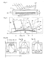
- FIG. 4 shows a in the surface elements 17 ( Fig. 2 ) until 19 ( Fig. 2 ) shaped diffraction grating 32, the microscopically fine relief profile R (x, y), for example, has a sinusoidal, periodic profile cross section of constant profile height h and with the spatial frequency f.
- the averaged relief of the diffraction grating 32 defines a central surface 33 arranged parallel to the cover layer 4.
- the parallel incident light 11 penetrates the cover layer 4 and the impression layer 5 and is applied to the optically effective structure 9 (FIG. Fig. 1 ) of the diffraction grating 32 deflected.
- the parallel diffracted light beams 34 of the wavelength ⁇ leave the security element 2 in the line of sight of an observer 35, who in the illumination of the surface pattern 12 (FIG. Fig. 2 ) with the parallel incident light 11, the colored, brightly radiating surface elements 17, 18, 19 sees.
- FIG. 5 lies the diffraction plane 20 in the plane of the drawing.
- a diffraction structure S (x, y) is formed, the central surface 33 of which is arched or inclined locally to the surface of the layer composite 1.
- the diffraction structure S (x, y) is a function of the coordinates x and y in the plane of the surface pattern 12 parallel to the surface of the layer composite 1 (FIG. Fig. 2 ), in which the surface parts 13, 14 ( Fig. 2 ), 15 lie.
- the relief profile R (x, y) generates the periodic diffraction grating 32 with the profile of one of the known sinusoidal, asymmetrical or symmetrical sawtooth or rectangular shapes.
- the microscopically fine relief profile R (x, y) of the diffraction structure S (x, y) is a matte structure instead of the periodic diffraction grating 32.
- the matte structure is a microscopically fine stochastic structure having a predetermined scattering characteristic for the incident light 11, wherein in an anisotropic matt structure instead of the grid vector, a preferred direction occurs.
- the matte structures scatter the perpendicularly incident light into a scattering cone having an aperture angle predetermined by the scattering power of the matte structure and the direction of the reflected light 22 as the cone axis.
- the intensity of the scattered light is e.g.
- the cross section of the scattering cone perpendicular to the cone axis is rotationally symmetric in a matt structure referred to here as "isotropic".
- the matte structure is here called "anisotropic".
- the profile height h ( Fig. 4 ) of the relief profile R (x, y) in the region of the overlay function M (x, y) is not changed, ie the relief profile R (x; y) follows the overlay function M (x, y).
- the uniquely defined superimposition function M (x, y) is at least piecewise differentiable and curved at least in partial areas, ie ⁇ M (x, y) ⁇ 0, periodic or aperiodic and is not a periodic triangular or rectangular function.
- the periodic superposition functions M (x, y) have a spatial frequency F of at most 20 lines / mm.
- links between two adjacent extreme values of the overlay functions M (x, y) are at least 0.025 mm long.
- the preferred values for the spatial frequency F are limited to at most 10 lines / mm and the preferred values for the distance between adjacent extreme values are at least 0.05 mm.
- the superimposition function M (x, y) thus varies as a macroscopic function in the continuous range slowly compared to the relief profile R (x, y).
- the superimposition function M (x, y) has a gradient 38, grad (M (x, y)) at each point P (x, y) on the sections lying parallel to the track 36 with continuous sections.
- the gradient 38 means the component of the degree (M (x, y)) in the diffraction plane 20, since the observer 35 defines the optically effective diffraction plane 20.
- the diffraction grating 32 has, in each point of the surface part 13, 14, 15, a gradient ⁇ predetermined by the gradient 38 of the superposition function M (x, y).
- the deformation of the central surface 33 causes a new, advantageous optical effect. This effect is explained by the diffraction behavior at transmission points A, B, C of the surface normal 21 and normal 21 ', 21 "to the central surface 33, eg along the track 36.
- the refraction of the incident light 11, the reflected light 22 and the diffracted light Light rays 34 at the boundary surfaces of the layer composite 1 is the sake of simplicity in the drawing of FIG. 5 not shown and not included in the following calculations.
- the inclination ⁇ is determined by the gradient 38.
- the normals 21 'and 21 ", the grating vector of the diffraction grating 32 ( Fig.
- the angle of incidence ⁇ ( Fig. 3 ), which are enclosed by the dashed lines 21, 21 ', 21 "and the white, parallel incident light 11.
- This also changes the wavelength ⁇ of the diffracted light beams 34 deflected in a predetermined viewing direction 39 to the observer 35. If the normal 21' tilted away by the viewer 35, the wavelength ⁇ of the diffracted light beams 34 is greater than when the normal 21 "to the observer 35 is tilted.
- the color bands of the spectrum can be seen by the observer 35 at a distance of 30 cm, at least 2 mm in length or more must be selected for the distance between the throughput points A and C.
- the surface of the surface part 13, 14, 15 has a faint gray.
- the angle of incidence ⁇ changes.
- the visible color bands of the spectra shift continuously in the region of the overlay function M (x, y) along the track 36.
- the color of the diffracted light beam 34 changes in the piercing point A ins Yellow-green, the color of the diffracted light beam 34 in the piercing point B to the blue and the color of the diffracted light beam 34 in the piercing point C in violet.
- the observer 35 perceives the change in the colors of the diffracted light 34 as migration of the color bands in a continuous manner over the surface part 13, 14, 15.
- the number of color bands of how many diffraction orders the observer sees on the surface part 13, 14, 15 simultaneously depends on the spatial frequency of the diffraction grating 32 and the number of periods and the amplitude of the superposition function M (x, y) within the surface part 13, 14, 15 from.
- the observer 35 sees in the direction of the reflected light 22 only a bright, white-gray band instead of the ribbons.
- the bright, whitish-gray band is visible to the observer 35 as a function of the scattering power of the matt structure, even if the color band is flat over the surface of the surface part 13, 14, 15 Viewing direction 39 is oblique to the diffraction plane 20.
- strip 40 ( Fig. 6a ) meant both the color bands of a diffraction order 23, 24, 25 and the bright white-gray band produced by the matt structure.
- Fig. 6a is the displacement of the strip from the observer 35 (FIG. Fig. 5 ) easier to recognize when a reference to the security feature 16 is present.
- a reference to the security feature 16 Serve as a reference on the surface portion 13, 14, 15, for example, on the central surface portion 14, arranged identification marks 37 ( Fig. 2 ) and / or a predetermined boundary shape of the surface part 13, 14, 15.
- the reference specifies a predetermined viewing condition, which is determined by tilting the layer composite 1 (FIG. Fig. 1 ) is adjustable so that the strip 40 is positioned predetermined against the reference.
- the optically active structure 9 (FIG. Fig. 1 ) of the interface 8 ( Fig.
- a light-absorbing imprint on the security feature 16 can also be used as a reference for the movement of the strip 40, or the identification mark 37 is produced by means of the structured reflection layer.
- the security feature 16 serve the adjacent on both sides of the central surface portion 14, adjacent surface portions 13 and 15 as a mutual reference.
- the adjacent surface parts 13 and 15 both have a diffraction structure S * (x, y).
- the security feature 16 along the coordinate axis y or the track 36 has a dimension of at least 5 mm, preferably more than 10 mm.
- the dimensions along the coordinate axis x are more than 0.25 mm, but preferably at least 1 mm.
- the oval surface part 14 has the diffraction structure S (y) dependent only on the coordinate y, while the surface parts 13 and 15 with the diffraction structure S * (y) dependent only on the coordinate y on both sides of the oval surface part 14 along the coordinate y extend.
- the gradient 38 ( Fig. 5 ) and the grating vector of the diffraction grating 32 (FIG. Fig. 4 ) or the preferred direction of the "anisotropic" matt structure are aligned substantially parallel or anti-parallel to the direction of the coordinate y.
- the azimuth ⁇ of the grating vector or the preferred direction of the matt structure is related to a gradient plane which is determined by the gradient 38 and the surface normal 21.
- the azimuth ⁇ is not limited to the said preferred values.
- the strip 40 is in the drawing of FIGS. 6a to 6c Narrow drawn to clearly show the movement effect.
- the width of the strips 40 in the direction of the unsigned arrows depends on the diffraction structure S (y). Particularly in the case of the color bands, the spectral color gradient extends over a larger part of the surface part 13, 14, 15, so that the movement of the strips 40 can be observed on the basis of the wandering of a detail in the visible spectrum, for example the red color band.
- FIG. 6b shows the security feature 16 after rotation about the tilting axis 41 in a predetermined tilt angle, below which the strips 40 of the two outer surface portions 13, 15 and the central surface portion 14 lie on a line parallel to the tilting axis 41.
- This predetermined tilt angle is determined by the choice of the overlay structure M (x, y).
- the security element 2 ( Fig. 2 ) is on the surface pattern 12 ( Fig. 2 ) to see a predetermined pattern only when in the security feature 16, the strip or strips 40 occupy a predetermined position, ie when the observer 35 views the security element 2 under the viewing conditions determined by the predetermined tilt angle.
- FIG. 7 shows a cross section along the track 36 ( Fig. 2 ) through the layer composite 1, for example in the region of the surface part 14 (FIG. Fig. 2 ). So that the layer composite 1 is not too thick and thus difficult to manufacture or use, the structural height H St ( Fig. 1 ) of the diffraction structure S (x; y).
- the overlay function M (y) 0.5 • y 2 • K left of the coordinate axis z, in which the height of the layer composite 1 expands, shown in section alone.
- the superposition function M (y) on a discontinuity point at which on the side remote from the point P 0 the value of the overlay function M (y) is reduced by the value H to the height z 0 , that is in the diffraction structure
- the function C (x; y) is limited in terms of amount to a range of values, for example to half the value of the structure height H ST .
- the discontinuities of the function ⁇ M (x; y) + C (x; y) ⁇ modulo Hub H-C (x; y) generated for technical reasons are not to be counted as extreme values of the superposition function M (x; y).
- the values for the hub H may be locally smaller.
- the locally varying stroke H is determined by the distance between two consecutive points of discontinuity P n not exceeding a predetermined value in the range from 40 ⁇ m to 300 ⁇ m.
- the diffraction structure S (x, y) extends on both sides of the coordinate axis z and not only as in the drawing of FIG FIG. 7 is shown, to the right of the coordinate axis z.
- the structure height H St is the sum of the stroke H and the profile height h (FIG. Fig. 4 ) and equal to the value of the diffraction structure S (x, y) at point P (x; y).
- the structure height H St is advantageously less than 40 ⁇ m, preferred values of the structure height H St being ⁇ 5 ⁇ m.
- M x ⁇ y 0 . 5 • x 2 + y 2 • K .
- M x ⁇ y a • 1 + sin 2 ⁇ ⁇ F x • x • sin 2 ⁇ ⁇ F y • y .
- the overlay functions M (x, y) are periodically composed of a predetermined section of another function and have one or more periods along the track 36.
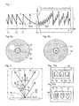
- the observer 35 detects in daylight according to the viewing direction 39 ( Fig. 5 ), a bright white-gray spot 42 against a dark gray background 43, wherein the position of the spot 42 in the surface part 14 with respect to the identification mark 37 and the contrast between the spot 42 and the background 43 are dependent on the viewing direction 39.
- the extent of the stain 42 is determined by the scattering power of the matte structure and the curvature of the superposition function M (x, y).
- the security element 2 ( Fig. 2 ) is, for example, by tilting about the tilting axis 41 (FIG. Fig. 5 ) and / or rotating about the surface normal 21 (FIG. Fig. 5 ) of the layer composite 1 ( Fig. 5 ) like in the FIG. 8b in such a way to align the predetermined viewing direction 39, that the spot 42 is located within the identification mark 37, which is arranged for example in the center of the circularly surrounded surface portion 14.
- the FIG. 9 shows the diffractive effect of the diffraction structure S (x, y) ( Fig. 7 ) in the diffraction plane 20.
- the relief structure R (x, y) ( Fig. 4 ) is the diffraction grating 32 (FIG. Fig. 4 ) with an eg sinusoidal profile and with a spatial frequency f less than 2400 lines / mm.
- the grating vector of the relief structure R (x, y) lies in the diffraction plane 20.
- first beams 44 having the wavelength ⁇ 1 with the incident light 11 include the viewing angle ⁇ and second beams 45 having the wavelength ⁇ 2 include the viewing angle - ⁇ .
- the observer 35 sees the surface portion 13, 14, 15 at the viewing angle ⁇ in the color with the wavelength ⁇ 1 .
- the observer 35 sees the surface part 13, 14, 15 at the viewing angle - ⁇ in the color of the wavelength ⁇ 2 .
- Equation (1) is easy to deduce for other atomic numbers m.
- the ordinal numbers m and the viewing angle ⁇ for a particular observable color are determined by the spatial frequency f.
- FIG. 10a and 10b is an example of an embodiment of the security feature 16, wherein in the FIG. 10a the security element 2 against the security element 2 in the FIG. 10b rotated in its plane by 180 °.
- the diffraction plane 20 ( Fig. 9 ) is shown with its track 36.
- a background field 46 adjoins at least one surface part 13, 14, 15 and has the diffraction grating 32 (FIG. Fig. 4 ) with the same relief profile R (x, y) and the background field 46 own Spatialfrequenz f.
- the grating vector of the relief profile R (x, y) is aligned parallel to the track 36 in the surface parts 13, 14, 15 and in the background field 46.
- white light 11 shine in the security feature 16 in the orientation of the FIG. 10a under the viewing angle + ⁇
- the surface parts 13, 14, 15 and the background field 46 in the same color
- the observer 35 (FIG. Fig. 5 ) the security feature 16 appears to illuminate without contrast in a uniform color, for example, the deflected first beams 44 (FIG. Fig. 9 ) the wavelength ⁇ 1 , eg 680 nm (red), on.
- the entire security feature 16 is observed under the viewing angle - ⁇ .
- the middle surface 33 (FIG. Fig. 9 ) of the diffraction grating 32 ( Fig. 4 ) the inclination ⁇ ( Fig.
- the advantage of this embodiment is the conspicuous optical behavior of the security feature 16, namely the color contrast visible under a single predetermined orientation of the security element 2 after a 180 ° rotation of the security element 2 around the surface normal 21 (FIG. Fig. 3 ) changes or disappears.
- the security feature 16 thus serves to define a predetermined orientation of the security element 2 with the non-holographically copied security feature 16.
- each surface part 13, 14, 15 has a section of the superimposition function M (x, y), so that the inclination ⁇ in the surface part 13, 14, 15 continuously changes in a predetermined direction and the wavelengths of the second rays 45 out an area on both sides of the wavelength ⁇ k originate.
- the similarly limited surface portions 13, 14, 15 form a plurality of arranged on the background field 46 surface portions 13, 14, 15 a logo, a lettering, etc.
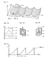
- the eg rectangular surface part 13, 14 (FIG. Fig. 10 ), 15 ( Fig. 10 ) is aligned with its longitudinal side parallel to the coordinate x and divided into narrow sub-areas 47 of the width b, whose longitudinal sides are aligned parallel to the coordinate axis y.
- Each period 1 / F x of the overlay structure M (x; y) extends over a number t of the partial surfaces 47, eg the number t is in the value range from 5 to 10.
- the width b should not fall below 10 ⁇ m, since otherwise the diffraction structure S (x, y) is not defined enough on the partial surface 47.
- the diffraction structures S (x, y) of the adjacent sub-areas 47 differ in the summands, the relief profile R (x, y) and the section of the superimposition function M (x, y) assigned to the subarea 47.
- the relief profile R i (x, y) of the i-th partial surface 47 differs from the two relief profiles R i + 1 (x, y) and R i-1 (x, y) of the adjacent partial surfaces 47 by at least one lattice parameter, such as Azimuth, spatial frequency, profile h ( Fig. 4 ), etc. If the spatial frequency F x or F y is at most 10 lines / mm but not less than 2.5 lines / mm, the observer 35 (FIG. Fig.
- the relief profile R (x, y) changes continuously as a function of the phase angle of the periodic overlay function M (x, y).
- the in the FIG. 11 shown diffraction structures S (x, y) are in the embodiment of the in Figures 12 shown security feature 16 deployed, which unfolds a novel, optical effect in the illumination with white light 11 when the security feature 16 is tilted about the coordinate axis y parallel to the tilting axis 41.
- the security feature 16 comprises the triangular first surface part 14, which is arranged in the rectangular second surface part 13.
- the diffraction structure S (x, y) is characterized in that the spatial frequency f of the relief profile R (x, y) in the direction of the coordinate axis x within each period of the superposition function M (x, y) is gradual or continuous a predetermined Spatialfrequenz- area changed ⁇ f, wherein the spatial frequency f i in the ith subarea 47 ( Fig. 7 ) is greater than the spatial frequency f i-1 in the preceding (i-1) -th sub-area 47.
- the first sub-area 47 has the spatial frequency f with the value f A.
- the diffraction structure S (x, y) is characterized in that the spatial frequency f of the relief profile R (x, y) in the direction of the coordinate axis x within a period of the superimposition function M (x, y) of the one face 47 to the next stepwise or continuously reduced.
- the grating vectors and the track 36 (FIG. Fig. 11 ) of the diffraction plane 20 ( Fig. 9 ) are aligned in two surface portions 13, 14 substantially parallel to the tilting axis 41.
- the gradient 38 is substantially parallel to the plane spanned by the coordinate axes x and z.
- the security feature 16 lies in the x - y plane spanned by the coordinate axes x and y, the viewing direction 39 (FIG. Fig. 5 ) forms a right angle with the coordinate axis x.
- the partial areas 47 are illuminated in the region of the minima of the superposition function M (x, y). Since these partial surfaces 47 in both diffraction structures S (x, y), S ** (x, y) have the same relief profile R (x, y) and the same inclination ⁇ ⁇ 0 °, the two surface parts 13, 14 in the viewing direction 39 diffracted light beams 34 ( Fig.
- FIG. 12c is the security feature 1 of the in the FIG. 12a shown tilted position about the tilting axis 41 to the right. Even when tilting to the right, the color contrast is clear, but with reversed colors.
- the color of the first surface part 14 shifts in the direction of blue, since the partial surfaces 47 become effective, in which the spatial frequency f of the relief profile R (x, y) is greater than the value f M , while the color of the second surface part 13 in the direction Red shifts because the faces 47 ( Fig. 11 ), in which the spatial frequency f of the relief profile R (x, y) of the diffraction structure S ** (x, y) decreases with respect to the value f M.
- the relief profile R (x, y) in the sub-areas 47 of each period 1 / F x has the same spatial frequency f, but the relief profile R (x, y) differs from sub-area 47 to sub-area 47 by its azimuth angle ⁇ of the grid vector relative to the coordinate axis y.
- the azimuth angle ⁇ is dependent on the local inclination ⁇ ( Fig.
- the second surface part 13 (12a) in which the mirrored diffraction structure S ** (x, y) is formed is ejected only at a single predetermined tilt angle in the predetermined color, for example, in a mixed color generated from the green region. lights. At other angles of tilt, the second surface part 13 is dark gray.
- the overlay function M (x, y) employed in the diffraction structure S (x, y) is an asymmetric function in the coordinate axis x direction.
- the spatial frequency F x or F y is in the range of 2.5 lines / mm to and 10 lines / mm. Not shown are the points of discontinuity caused by Operation Modulo Hub H ( Fig. 7 ) arise.
- FIGS. 12a to 12c For example, instead of a single triangular first surface part 14 on the second surface part 13, a plurality of the first surface parts 14 may be arranged, which form a logo, a lettering, etc.
- relief images are also used as at least piecewise continuous superimposition function M (x, y) in the diffraction structure S (x, y), wherein advantageously the relief profile R (x, y) is an "isotropic" matte structure.
- the observer of the security element 2 in this embodiment receives the impression of a three-dimensional image with a characteristic surface structure. When rotating and tilting the security element 2, the brightness distribution in the image changes according to the expectation in a true relief image, but projecting elements do not cast a shadow.
- all diffraction structures S are in their structural height to the value H St ( Fig. 1 ), as indicated by the FIG. 7 was explained.
- the relief profiles R (x, y) and overlay functions M (x, y) used in the special embodiments described above can be combined as desired to form other diffraction structures S (x, y).
- the use of the security features 16 described above in the security element 2 has the advantage that the security feature 16 forms an effective barrier against attempts to holographically copy the security element 2.
- the positional shifts or color shifts on the surface of the security feature 16 can be recognized only in a modified form.
Abstract
Description
Die Erfindung bezieht sich auf ein Sicherheitselement gemäss dem Oberbegriff des Anspruchs 1.The invention relates to a security element according to the preamble of
Solche Sicherheitselemente bestehen aus einem dünnen Schichtverbund aus Kunststoff, wobei in den Schichtverbund wenigstens Reliefstrukturen aus der Gruppe Beugungsstrukturen, Licht streuende Strukturen und ebene Spiegelflächen eingebettet sind. Die aus dem dünnen Schichtverbund geschnittenen Sicherheitselemente werden auf Gegenstände geklebt zum Beglaubigen der Echtheit der Gegenstände.Such security elements consist of a thin composite layer of plastic, wherein at least relief structures from the group of diffraction structures, light-scattering structures and planar mirror surfaces are embedded in the layer composite. The cut from the thin layer composite security elements are glued to objects to authenticate the authenticity of the objects.
Der Aufbau des dünnen Schichtverbunds und die dazu verwendbaren Materialien sind beispielsweise in der
Eine Anordnung der eingangs genannten Art ist aus der
Es ist auch bekannt, die Sicherheitselemente mit Merkmalen auszurüsten, die ein Nachmachen bzw. ein Kopieren mit üblichen holographischen Mitteln erschweren oder gar verunmöglichen. Beispielsweise sind aus der
Die
Die in den beispielhaft genannten Dokumenten
Der Erfindung liegt die Aufgabe zugrunde, ein kostengünstiges, neuartiges Sicherheitselement zu schaffen, das eine hohe Resistenz gegen Fälschungsversuche, z.B. mittels eines holographischen Kopierverfahrens aufweisen soll.The invention has for its object to provide a cost-effective, novel security element, which has a high resistance to counterfeiting attempts, e.g. by means of a holographic copying method.
Diese Aufgabe wird durch ein Sicherheitselement nach Anspruch 1 gelöst.This object is achieved by a security element according to
Vorteilhafte Ausgestaltungen der Erfindung ergeben sich aus den Unteransprüchen.Advantageous embodiments of the invention will become apparent from the dependent claims.
Es zeigen:
Figur 1- ein Sicherheitselement im Querschnitt,
Figur 2- das Sicherheitselement in Draufsicht,
Figur 3- Reflexion und Beugung an einem Gitter,
Figur 4- Beleuchtung und Beobachtung des Sicherheitselements,
- Figur 5
- Reflexion und Beugung an einer Beugungsstruktur,
- Figuren 6
- das Sicherheitsmerkmal unter verschiedenen Kippwinkeln,
- Figur 7
- eine Überlagerungsfunktion und die Beugungsstruktur im Querschnitt,
Figuren 8- das Ausrichten des Sicherheitselements mittels Kennmarken,
Figur 9- einen lokalen Neigungswinkel der Überlagerungsfunktion,
Figuren 10- das Ausrichten des Sicherheitselements mittels Farbkontrast im Sicherheitsmerkmal,
Figur 11- die Beugungsstruktur mit symmetrischer Überlagerungsfunktion,
Figuren 12- das Sicherheitsmerkmal mit Farbumschlag und
Figur 13- eine asymmetrische Überlagerungsfunktion.
- FIG. 1
- a security element in cross section,
- FIG. 2
- the security element in plan view,
- FIG. 3
- Reflection and diffraction on a grid,
- FIG. 4
- Lighting and observation of the security element,
- FIG. 5
- Reflection and diffraction at a diffraction structure,
- FIGS. 6
- the security feature at different tilt angles,
- FIG. 7
- an overlay function and the diffraction structure in cross section,
- FIGS. 8
- the alignment of the security element by means of identification marks,
- FIG. 9
- a local tilt angle of the overlay function,
- Figures 10
- the alignment of the security element by means of color contrast in the security feature,
- FIG. 11
- the diffraction structure with symmetrical overlay function,
- Figures 12
- the security feature with color change and
- FIG. 13
- an asymmetric overlay function.
In der
Die gemeinsame Berührungsfläche zwischen der Abformschicht 5 und der Schutzschicht 6 ist die Grenzfläche 8. In die Abformschicht 5 sind die optisch wirksamen Strukturen 9 mit einer Strukturhöhe HSt eines optisch variablen Musters abgeformt. Da die Schutzschicht 6 die Täler der optisch wirksamen Strukturen 9 verfüllt, weist die Grenzfläche 8 die Form der optisch wirksamen Strukturen 9 auf. Um eine hohe Wirksamkeit der optisch wirksamen Strukturen 9 zu erhalten, ist die Grenzfläche 8 mit einem Metallbelag versehen, vorzugsweise aus den Elementen der Tabelle 5 der eingangs erwähnten
Der Schichtverbund 1 wird als Kunststofflaminat in Form einer langen Folienbahn mit einer Vielzahl von nebeneinander angeordneten Kopien des optisch variablen Musters hergestellt. Aus der Folienbahn werden die Sicherheitselemente 2 beispielsweise ausgeschnitten und mittels der Kleberschicht 7 mit einem Substrat 3 verbunden. Das Substrat 3, meist in Form eines Dokuments, einer Banknote, einer Bankkarte, eines Ausweises oder eines anderen wichtigen bzw. wertvollen Gegenstandes, wird mit dem Sicherheitselement 2 versehen, um die Echtheit des Gegenstandes zu beglaubigen.The
Die
Anhand der
Die
In der
In einer anderen Ausführung ist das mikroskopisch feine Reliefprofil R(x, y) der Beugungsstruktur S(x, y) eine Mattstruktur anstelle des periodischen Beugungsgitters 32. Die Mattstruktur ist eine mikroskopisch feine, stochastische Struktur mit einer vorbestimmten Streucharakteristik für das einfallende Licht 11, wobei bei einer anisotropen Mattstruktur anstelle des Gittervektors eine Vorzugsrichtung tritt. Die Mattstrukturen streuen das senkrecht einfallende Licht in einen Streukegel mit einem durch das Streuvermögen der Mattstruktur vorbestimmten Öffnungswinkel und mit der Richtung des reflektierten Lichts 22 als Kegelachse. Die Intensität des Streulichts ist z.B. auf der Kegelachse am grössten und nimmt mit zunehmendem Abstand zur Kegelachse ab, wobei das in Richtung der Mantellinien des Streukegels abgelenkte Licht für einen Beobachter gerade noch erkennbar ist. Der Querschnitt des Streukegels senkrecht zur Kegelachse ist rotationssymmetrisch bei einer hier "isotrop" genannten Mattstruktur. Ist der Querschnitt in der Vorzugsrichtung hingegen gestaucht d.h. elliptisch verformt mit der kurzen Hauptachse der Ellipse parallel zur Vorzugsrichtung, wird die Mattstruktur hier mit "anisotrop" bezeichnet.In another embodiment, the microscopically fine relief profile R (x, y) of the diffraction structure S (x, y) is a matte structure instead of the
Wegen der additiven bzw. subtraktiven Überlagerung wird die Profilhöhe h (
Eine auf die Ebene des Flächenmusters 12 (
Die Deformation der Mittelfläche 33 bewirkt eine neue, vorteilhafte optische Wirkung. Diese Wirkung wird anhand des Beugungsverhaltens in Durchstosspunkten A, B, C der Flächennormale 21 und Normalen 21', 21" auf die Mittelfläche 33, z.B. längs der Spur 36, erklärt. Die Brechung des einfallenden Lichts 11, des reflektieren Lichts 22 und der gebeugten Lichtstrahlen 34 an den Grenzflächen des Schichtverbunds 1 ist der Einfachheit halber in der Zeichnung der
Diese Überlegung ist für jede Beugungsordnung zutreffend. Wie viele Farbbänder von wie vielen Beugungsordnungen der Beobachter auf dem Flächenteil 13, 14, 15 gleichzeitig erblickt, hängt von der Spatialfrequenz des Beugungsgitters 32 und der Anzahl Perioden und der Amplitude der Überlagerungsfunktion M(x, y) innerhalb des Flächenteils 13, 14, 15 ab.This consideration is true for any diffraction order. The number of color bands of how many diffraction orders the observer sees on the
In einer anderen Ausführung, bei der eine der Mattstrukturen anstelle des Beugungsgitters 32 eingesetzt ist, erblickt der Beobachter 35 in der Richtung des reflektierten Lichts 22 nur ein helles, weissgraues Band anstelle der Farbbänder. Das helle, weissgraue Band wandert beim Kippen wie die Farbbänder kontinuierlich über die Fläche des Flächenteils 13, 14, 15. Im Gegensatz zu den Farbbänder ist das helle, weissgraue Band für den Beobachter 35 in Abhängigkeit vom Streuvermögen der Mattstruktur auch dann sichtbar, wenn seine Betrachtungsrichtung 39 schief zur Beugungsebene 20 ist. Nachstehend ist daher mit "Streifen 40" (
In der
In einer weiteren Ausführung des Sicherheitsmerkmals 16 nach den
In der Ausführung des Sicherheitsmerkmals 16 gemäss den
Im allgemeinen ist der Azimut ϕ des Gittervektors bzw. der Vorzugsrichtung der Mattstruktur auf eine Gradientenebene bezogen, die durch den Gradienten 38 und die Flächennormale 21 bestimmt ist. Die Vorzugswerte des Azimuts ϕ sind 0° und 90°. Dabei sind Abweichungen im Azimutwinkel des Gittervektors bzw. der Vorzugsrichtung von δϕ = ±20° auf den Vorzugswert zulässig, um in diesem Bereich den Gittervektor bzw. die Vorzugsrichtung als im wesentlichen parallel bzw. senkrecht zur Gradientenebene zu betrachten. An sich ist der Azimut ϕ nicht auf die genannten Vorzugswerte beschränkt.In general, the azimuth φ of the grating vector or the preferred direction of the matt structure is related to a gradient plane which is determined by the
Je kleiner die Krümmung K ist, desto höher ist die Geschwindigkeit der Bewegung der Streifen 40 in Richtung der in der Zeichnung der
Die
In der
Selbstverständlich reichen für das Sicherheitsmerkmal 16 in einer anderen Ausführung eine benachbarte Anordnung aus dem mittleren Flächenteil 14 und einem der beiden Flächenteile 13, 15 aus.Of course, sufficient for the
Die ![]()
![]()
Die Funktion C(x; y) ist dabei betragsmässig auf einen Wertebereich beschränkt, beispielsweise auf den halben Wert der Strukturhöhe HST. Die aus technischen Gründen erzeugten Unstetigkeitsstellen der Funktion {M(x; y) + C(x; y)} modulo Hub H - C(x; y) sind nicht als Extremwerte der Überlagerungsfunktion M(x; y) zu zählen. Ebenso können in bestimmten Ausführungen die Werte für den Hub H lokal kleiner sein. In einer Ausführung der Beugungsstruktur S(x; y) ist der lokal variierende Hub H dadurch bestimmt, dass der Abstand zwischen zwei aufeinanderfolgenden Unstetigkeitsstellen Pn einen vorbestimmten Wert aus dem Bereich von 40 µm bis 300 µm nicht überschreitet.The function C (x; y) is limited in terms of amount to a range of values, for example to half the value of the structure height H ST . The discontinuities of the function {M (x; y) + C (x; y)} modulo Hub H-C (x; y) generated for technical reasons are not to be counted as extreme values of the superposition function M (x; y). Likewise, in certain implementations, the values for the hub H may be locally smaller. In one embodiment of the diffraction structure S (x; y), the locally varying stroke H is determined by the distance between two consecutive points of discontinuity P n not exceeding a predetermined value in the range from 40 μm to 300 μm.
In den Flächenteilen 13 (
Weitere Beispiele der Überlagerungsfunktion M(x, y) sind: ![]()
![]()
M(x, y) = a•x1,5 + b•x, M(x, y) = a•{1 + sin(2πFy•y)}, wobei Fx bzw. Fy die Raumfrequenz F der Überlagerungsfunktion M(x, y) in Richtung der Koordinatenachse x bzw. y ist. In einer anderen Ausführung des Sicherheitsmerkmals 16 ist die Überlagerungsfunktionen M(x, y) aus einem vorbestimmten Ausschnitt einer anderen Funktion periodisch zusammengesetzt und weist eine oder mehrere Perioden längs der Spur 36 auf.M (x, y) = a • x 1.5 + b • x, M (x, y) = a • {1 + sin (2πF y • y)}, where F x or F y is the spatial frequency F of the Overlay function M (x, y) in the direction of the coordinate axis x and y, respectively. In another embodiment of the
In der
Die
Wegen ξk = asin(sinα + mk•λk•f) und α = γ ergibt sich für die beiden ersten Beugungsordnungen 23, 24, d.h. für mk = ±1, die Beziehung ![]()
woraus folgt, dass für vorbestimmte Werte des Betrachtungswinkels ϑ und der Spatialfrequenz f die Summe der beiden Wellenlängen λ1, λ2 der Strahlen 44, 45 proportional zum Kosinus des lokalen Neigungswinkels γ ist. Die Gleichung (1) ist für andere Ordnungszahlen m leicht herzuleiten. Die Ordnungszahlen m und der Betrachtungswinkel ϑ für eine bestimmte, beobachtbare Farbe sind durch die Spatialfrequenz f bestimmt.Because ξ k = asin (sin α + m k • λ k • f) and α = γ, the relationship for the two ![]()
From this it follows that for predetermined values of the viewing angle θ and the spatial frequency f, the sum of the two wavelengths λ 1 , λ 2 of the
In den
Nur der Einfachheit halber ist in jedem Flächenteil 13, 14, 15 eine einheitliche Farbe, d.h. eine konstante Neigung γ, als Beispiel angenommen worden. Im allgemeinen weist das Flächenteil 13, 14, 15 einen Ausschnitt aus der Überlagerungsfunktion M(x, y) auf, so dass sich die Neigung γ im Flächenteil 13, 14, 15 in einer vorbestimmten Richtung kontinuierlich ändert und die Wellenlängen der zweiten Strahlen 45 aus einem Bereich beiderseits der Wellenlänge λk stammen. Anstelle der gleichartig begrenzten Flächenteile 13, 14, 15 bilden eine Vielzahl der auf dem Hintergrundfeld 46 angeordneten Flächenteile 13, 14, 15 ein Logo, einen Schriftzug usw.For the sake of simplicity only, a uniform color, ie a constant inclination γ, has been assumed in each
In der
Die Beugungsstrukturen S(x, y) der benachbarten Teilflächen 47 unterscheiden sich in den Summanden, dem Reliefprofil R(x, y) und dem der Teilfläche 47 zugeordneten Ausschnitt der Überlagerungsfunktion M(x, y). Das Reliefprofil Ri(x, y) der i-ten Teilfläche 47 unterscheidet sich von den beiden Reliefprofilen Ri+1(x, y) und Ri-1(x, y) der benachbarten Teilflächen 47 um wenigstens einen Gitterparameter, wie Azimut, Spatialfrequenz, Profilhöhe h (
Die in der
In der
In einer anderen Ausführung der Beugungsstruktur S(x, y) der
In der
In den
In einer weiteren Ausführung finden anstelle der einfachen mathematischen Funktionen auch Reliefbilder, wie sie auf Münzen und Medaillen verwendet werden, als wenigstens stückweise stetige Überlagerungsfunktion M(x, y) in der Beugungsstruktur S(x, y) Verwendung, wobei mit Vorteil das Reliefprofil R(x, y) eine "isotrope" Mattstruktur ist. Der Beobachter des Sicherheitselements 2 in dieser Ausführung erhält den Eindruck eines dreidimensionalen Bildes mit einer charakteristischen Oberflächenstruktur. Beim Drehen und Kippen des Sicherheitselements 2 verändert sich die Helligkeitsverteilung im Bild entsprechend der Erwartung bei einem echten Reliefbild, jedoch werfen vorragende Elemente keinen Schatten.In a further embodiment, instead of the simple mathematical functions, relief images, as used on coins and medals, are also used as at least piecewise continuous superimposition function M (x, y) in the diffraction structure S (x, y), wherein advantageously the relief profile R (x, y) is an "isotropic" matte structure. The observer of the
Ohne von der Idee der Erfindung abzuweichen, sind alle Beugungsstrukturen S in ihrer Strukturhöhe auf den Wert HSt (
Die Verwendung der oben beschriebenen Sicherheitsmerkmale 16 im Sicherheitselement 2 weist den Vorteil auf, dass das Sicherheitsmerkmal 16 eine wirksame Barriere gegen Versuche bildet, das Sicherheitselement 2 holographisch zu kopieren. In einer holographischen Kopie sind die Lageverschiebungen bzw. Farbverschiebungen auf der Fläche des Sicherheitsmerkmals 16 nur in veränderter Form zu erkennen.The use of the security features 16 described above in the
Claims (15)
- Security element (2) from a layer composite (1) with microscopically fine, optically active structures (9) of an area pattern (12) which are embedded between transparent layers (4; 5; 6) of the layer composite (1), wherein the optically active structures (9) are moulded in subareas (13; 14; 15; 46) of a security feature (16) in a reflective boundary layer (8) between the layers (5; 6) on a plane of the area pattern (12) that is spanned by coordinate axes (x; y), characterized in that at least one subarea (13; 14; 15) with dimensions of greater than 0.4 mm has a diffraction structure (S; S*; S**) which is formed by additive or subtractive superposition of a superposition function (M), which describes a macroscopic structure, with a microscopically fine relief profile (R), with the superposition function (M), the relief profile (R) and the diffraction structure (S; S**; S**) being functions of the coordinates (x; y) and the relief profile (R) describing a light-diffusing optically active structure (9) which retains the predetermined relief profile (R) following the superposition function (M), and in that a middle surface (33), which is defined by the at least partially continuous superposition function (M), is curved at least in partial regions and has in each point a local inclination angle (γ), which is predetermined by the gradient of the superposition function (M), is not a periodic triangular or rectangular function and changes gradually in comparison with the relief profile (R).
- Security element (2) according to Claim 1, characterized in that the superposition function (M) is a partially continuous, periodic function with a spatial frequency (F) of at most 20 lines/mm.
- Security element (2) according to Claim 1, characterized in that the superposition function (M) is an asymmetric, partially continuous, periodic function with a spatial frequency (F) in the range of 2.5 lines/mm to 10 lines/mm.
- Security element (2) according to Claim 1, characterized in that, in the subarea (13; 14; 15), neighbouring extreme values of the superposition function (M) are spaced apart from each other by at least 0.025 mm.
- Security element (2) according to one of Claims 2 to 4, characterized in that the relief profile (R) is an anisotropic matt structure having a preferential direction with an azimuth angle (ϕ).
- Security element (2) according to Claim 5, characterized in that the security feature (16; 16') has at least two neighbouring subareas (13; 14; 15), and in that the first diffraction structure (S) is moulded in the first subarea (14) and the second diffraction structure (S*, S**), which differs from the first diffraction structure (S), is moulded in the second subarea (13; 15), wherein the preferential direction of the first relief profile (R) in the first subarea (14) and the preferential direction of the second relief profile (R) in the second subarea (13; 15) are aligned substantially parallel.
- Security element (2) according to one of Claims 5 to 6, characterized in that, in the diffraction structure (S; S*; S**), the preferential direction of the relief profile (R) is substantially parallel to a gradient plane that is determined by the gradient (38) of the superposition function (M) and a surface normal (21) which is perpendicular to the surface of the layer composite (1).
- Security element (2) according to one of Claims 5 to 7, characterized in that the first diffraction structure (S) is moulded in a first subarea (14), which first diffraction structure (S) is formed as a sum from the relief profile (R) and the superposition function (M), and in that the second diffraction structure (S*) is moulded in a second subarea (13; 15), which second diffraction structure is formed as a difference (R - M) from the same relief profile (R) and the same superposition function (M).
- Security element (2) according to one of Claims 5 to 8, characterized in that, in the diffraction structure (S; S*; S**), the preferential direction of the relief profile (R) is substantially perpendicular to a gradient plane which is determined by the gradient (38) of the superposition function (M) and a surface normal (21) which is perpendicular to the surface of the layer composite (1).
- Security element (2) according to Claim 5, characterized in that, in the first subarea (14), the first diffraction structure (S) is formed from the sum from the relief profile (R) and the superposition function (M), and in that, in the second subarea (13; 15), the diffraction structure (S**) is the first diffraction structure (S) which is mirrored at the plane of the area pattern (12
- Security element (2) according to Claim 1, characterized in that the relief profile (R) is an isotropic matt structure.
- Security element (2) according to Claim 11, characterized in that the superposition function (M) describes a relief image.
- Security element (2) according to Claim 11, characterized in that the superposition function (M) describes a spherical cap.
- Security element (2) according to one of Claims 1 to 13, characterized in that further area elements (17; 18; 19) with the optically active structures (9) are parts of the area pattern (12) and in that at least one of the area elements (17; 18; 19) adjoins the security feature (16).
- Security element (2) according to one of Claims 1 to 14, characterized in that at least one identifying mark (37) with an optically active structure (9) that differs from the diffraction structure (S; S*; S**) is arranged on at least one of the subareas (13; 14; 15) and in that the identifying mark (37), which can be used as a reference for aligning the layer composite (1), has one of the optically active structures (9) from the group of the diffractive or diffusing relief structures or a mirror surface.
Applications Claiming Priority (3)
| Application Number | Priority Date | Filing Date | Title |
|---|---|---|---|
| DE10216562 | 2002-04-05 | ||
| DE10216562A DE10216562C1 (en) | 2002-04-05 | 2002-04-05 | Security element with micro and macro structures |
| PCT/EP2003/003482 WO2003084764A2 (en) | 2002-04-05 | 2003-04-03 | Security element comprising micro- and macrostructures |
Publications (3)
| Publication Number | Publication Date |
|---|---|
| EP1492679A2 EP1492679A2 (en) | 2005-01-05 |
| EP1492679B1 EP1492679B1 (en) | 2010-11-10 |
| EP1492679B2 true EP1492679B2 (en) | 2014-06-25 |
Family
ID=28685061
Family Applications (1)
| Application Number | Title | Priority Date | Filing Date |
|---|---|---|---|
| EP03714917.6A Expired - Lifetime EP1492679B2 (en) | 2002-04-05 | 2003-04-03 | Security element comprising micro- and macrostructures |
Country Status (11)
| Country | Link |
|---|---|
| US (1) | US7680274B2 (en) |
| EP (1) | EP1492679B2 (en) |
| JP (2) | JP2005528633A (en) |
| CN (1) | CN100537267C (en) |
| AT (1) | ATE487611T1 (en) |
| AU (1) | AU2003219126A1 (en) |
| DE (2) | DE10216562C1 (en) |
| ES (1) | ES2356227T5 (en) |
| PL (1) | PL206879B1 (en) |
| RU (1) | RU2311304C2 (en) |
| WO (1) | WO2003084764A2 (en) |
Families Citing this family (24)
| Publication number | Priority date | Publication date | Assignee | Title |
|---|---|---|---|---|
| DE10318105B4 (en) * | 2003-03-21 | 2007-09-20 | Ovd Kinegram Ag | Process for the production of microstructures |
| DE502004004729D1 (en) | 2003-03-21 | 2007-10-04 | Ovd Kinegram Ag | Process for the preparation of two overlapping microstructures |
| DE102004003340A1 (en) * | 2004-01-22 | 2005-08-18 | Fraunhofer-Gesellschaft zur Förderung der angewandten Forschung e.V. | Flat substrate comprises a surface with structured elements that form a macro-structure, and a micro-structure which forms a second structure element |
| CN1989429B (en) * | 2004-07-21 | 2010-05-05 | 罗利克有限公司 | Anisotropic optical device and method for making same |
| DE102005006231B4 (en) * | 2005-02-10 | 2007-09-20 | Ovd Kinegram Ag | Method for producing a multilayer body |
| DE102005017169B4 (en) | 2005-04-13 | 2023-06-22 | Ovd Kinegram Ag | transfer film |
| DE102005017170B4 (en) | 2005-04-13 | 2010-07-01 | Ovd Kinegram Ag | Transfer film, process for their preparation and multilayer body and its use |
| EP2021840B2 (en) † | 2006-05-02 | 2022-09-21 | Surys | Optical security marking component, method of manufacturing such a component, system comprising such a component, and reader for checking such a component |
| US8133638B2 (en) * | 2006-05-30 | 2012-03-13 | Brady Worldwide, Inc. | All-polymer grating microstructure |
| EP1889732A1 (en) * | 2006-08-18 | 2008-02-20 | Setec Oy | Method of superimposing an image onto another, method of personalizing a data carrier using the the method |
| CN101910876A (en) * | 2008-04-18 | 2010-12-08 | 凸版印刷株式会社 | Labeling material and labeled goods item |
| DE102008028187A1 (en) * | 2008-06-12 | 2009-12-17 | Giesecke & Devrient Gmbh | Security element with optically variable element. |
| JP5470794B2 (en) * | 2008-09-30 | 2014-04-16 | 凸版印刷株式会社 | Display, adhesive label, transfer foil, and labeled article |
| FR2959830B1 (en) | 2010-05-07 | 2013-05-17 | Hologram Ind | OPTICAL AUTHENTICATION COMPONENT AND METHOD FOR MANUFACTURING THE SAME |
| EA018164B1 (en) * | 2011-09-26 | 2013-05-30 | Общество С Ограниченной Ответственностью "Центр Компьютерной Голографии" | Micro-optical system for forming images for visual control of product identity |
| EA017829B1 (en) * | 2011-09-26 | 2013-03-29 | Общество С Ограниченной Ответственностью "Центр Компьютерной Голографии" | Microoptic system for visual control of product authenticity |
| DE102012015900A1 (en) | 2012-08-10 | 2014-03-06 | Giesecke & Devrient Gmbh | Security element with coloreffective grid |
| EP3427968B2 (en) | 2013-03-12 | 2023-03-01 | Toppan Printing Co., Ltd. | Display |
| DE102013105246B4 (en) * | 2013-05-22 | 2017-03-23 | Leonhard Kurz Stiftung & Co. Kg | Optically variable element |
| RU2544772C1 (en) * | 2014-04-07 | 2015-03-20 | федеральное государственное бюджетное образовательное учреждение высшего профессионального образования "Московский государственный университет печати имени Ивана Федорова" (МГУП имени Ивана Федорова) | Method of authenticity control of multicolour printed products |
| CN105403947A (en) * | 2015-12-29 | 2016-03-16 | 上海宏盾防伪材料有限公司 | Safety layer structure with holographic image |
| GB2572745B (en) | 2018-03-22 | 2021-06-09 | De La Rue Int Ltd | Security elements and methods of manufacture thereof |
| JP7159631B2 (en) * | 2018-06-14 | 2022-10-25 | 大日本印刷株式会社 | Information recording medium |
| FR3121629B1 (en) * | 2021-04-09 | 2023-04-07 | Surys | Optical security components visible in reflection, manufacture of such components and secure documents equipped with such components |
Citations (4)
| Publication number | Priority date | Publication date | Assignee | Title |
|---|---|---|---|---|
| DE2701176B1 (en) † | 1976-12-21 | 1977-12-08 | Landis & Gyr Ag | Concealed identification code for credit cards etc. - is pressed in stress field and heated to reveal surface markings |
| JPS6366300U (en) † | 1986-10-22 | 1988-05-02 | ||
| WO2000061386A1 (en) † | 1999-04-09 | 2000-10-19 | Ovd Kinegram Ag | Decorative foil |
| WO2003043832A1 (en) † | 2001-11-23 | 2003-05-30 | Ovd Kinegram Ag | Security element with diffraction structures |
Family Cites Families (27)
| Publication number | Priority date | Publication date | Assignee | Title |
|---|---|---|---|---|
| CH659433A5 (en) | 1982-10-04 | 1987-01-30 | Landis & Gyr Ag | DOCUMENT WITH A REFLECTIVE OPTICAL SECURITY ELEMENT. |
| JPS5988780A (en) | 1982-11-08 | 1984-05-22 | アメリカン・バンク・ノ−ト・カムパニ− | Making of optical refraction recording body and optical refraction pattern |
| EP0201323B1 (en) * | 1985-05-07 | 1994-08-17 | Dai Nippon Insatsu Kabushiki Kaisha | Article incorporating a transparent hologramm |
| WO1988005387A1 (en) | 1987-01-13 | 1988-07-28 | Mancuso Robert J | Variable color print and method of making same |
| JPH0439040Y2 (en) * | 1987-06-22 | 1992-09-11 | ||
| US4874213A (en) * | 1987-08-10 | 1989-10-17 | Polaroid Corporation | Method of forming volume phase reflection holograms |
| ATE69407T1 (en) * | 1988-03-03 | 1991-11-15 | Landis & Gyr Betriebs Ag | DOCUMENT. |
| US5161057A (en) * | 1988-09-12 | 1992-11-03 | Johnson Kenneth C | Dispersion-compensated fresnel lens |
| DE58906429D1 (en) | 1988-09-30 | 1994-01-27 | Landis & Gyr Business Support | Diffraction element. |
| EP0429782B1 (en) | 1989-12-01 | 1994-05-18 | Landis & Gyr Technology Innovation AG | Arrangement for improving the falsification safety of a document of value |
| JP2543180Y2 (en) * | 1991-11-05 | 1997-08-06 | 帝人株式会社 | Pouch film |
| US5561558A (en) | 1993-10-18 | 1996-10-01 | Matsushita Electric Industrial Co., Ltd. | Diffractive optical device |
| JP3392500B2 (en) * | 1994-02-28 | 2003-03-31 | 凸版印刷株式会社 | Display with diffraction grating pattern |
| FR2726660B1 (en) * | 1994-11-03 | 1997-01-10 | Bernard Sermage | OPTICAL DIFFRACTION REFLECTIVE ARRAY AND METHODS OF MANUFACTURE |
| JP3556324B2 (en) * | 1995-06-16 | 2004-08-18 | 凸版印刷株式会社 | Hologram inspection apparatus and method |
| US6130777A (en) * | 1996-05-16 | 2000-10-10 | Dai Nippon Printing Co., Ltd. | Lenticular lens sheet with both a base sheet having lenticular elements and a surface diffusing part having elements of elementary shape smaller than lenticular elements |
| US6060143A (en) * | 1996-11-14 | 2000-05-09 | Ovd Kinegram Ag | Optical information carrier |
| DE59610252D1 (en) | 1996-12-12 | 2003-04-24 | Ovd Kinegram Ag Zug | SURFACE PATTERN |
| JPH11160509A (en) * | 1997-11-27 | 1999-06-18 | Toppan Printing Co Ltd | Display provided with diffraction grating pattern |
| CH693427A5 (en) | 1998-01-27 | 2003-07-31 | Ovd Kinegram Ag | Surface pattern. |
| JPH11224050A (en) * | 1998-02-05 | 1999-08-17 | Toppan Printing Co Ltd | Forgery preventive medium, seal and transfer foil |
| US6324004B1 (en) * | 1999-01-21 | 2001-11-27 | Ovd Kingegram Ag | Planar patterns with superimposed diffraction gratings |
| DE10028426A1 (en) * | 1999-06-10 | 2001-04-12 | Fraunhofer Ges Forschung | Manufacture of three-dimensional structure using coarse structure with recesses having edges inclined at angle between 0 and 90 degrees |
| DE19963849A1 (en) * | 1999-12-30 | 2001-07-12 | Giesecke & Devrient Gmbh | Data carrier with printed security element |
| CN1265216C (en) * | 2000-04-15 | 2006-07-19 | Ovd基尼格拉姆股份公司 | Pattern |
| GB0015873D0 (en) * | 2000-06-28 | 2000-08-23 | Rue De Int Ltd | Optically variable security device |
| DE10216561B4 (en) | 2002-04-05 | 2010-01-07 | Ovd Kinegram Ag | Security element with macrostructures |
-
2002
- 2002-04-05 DE DE10216562A patent/DE10216562C1/en not_active Expired - Lifetime
-
2003
- 2003-04-03 EP EP03714917.6A patent/EP1492679B2/en not_active Expired - Lifetime
- 2003-04-03 JP JP2003581986A patent/JP2005528633A/en active Pending
- 2003-04-03 AT AT03714917T patent/ATE487611T1/en active
- 2003-04-03 CN CNB038079321A patent/CN100537267C/en not_active Expired - Fee Related
- 2003-04-03 RU RU2004132228/12A patent/RU2311304C2/en not_active IP Right Cessation
- 2003-04-03 ES ES03714917.6T patent/ES2356227T5/en not_active Expired - Lifetime
- 2003-04-03 PL PL371208A patent/PL206879B1/en unknown
- 2003-04-03 DE DE50313255T patent/DE50313255D1/en not_active Expired - Lifetime
- 2003-04-03 AU AU2003219126A patent/AU2003219126A1/en not_active Abandoned
- 2003-04-03 WO PCT/EP2003/003482 patent/WO2003084764A2/en active Application Filing
- 2003-04-03 US US10/510,395 patent/US7680274B2/en not_active Expired - Fee Related
-
2010
- 2010-07-16 JP JP2010161408A patent/JP5695357B2/en not_active Expired - Fee Related
Patent Citations (4)
| Publication number | Priority date | Publication date | Assignee | Title |
|---|---|---|---|---|
| DE2701176B1 (en) † | 1976-12-21 | 1977-12-08 | Landis & Gyr Ag | Concealed identification code for credit cards etc. - is pressed in stress field and heated to reveal surface markings |
| JPS6366300U (en) † | 1986-10-22 | 1988-05-02 | ||
| WO2000061386A1 (en) † | 1999-04-09 | 2000-10-19 | Ovd Kinegram Ag | Decorative foil |
| WO2003043832A1 (en) † | 2001-11-23 | 2003-05-30 | Ovd Kinegram Ag | Security element with diffraction structures |
Also Published As
| Publication number | Publication date |
|---|---|
| EP1492679B1 (en) | 2010-11-10 |
| AU2003219126A8 (en) | 2003-10-20 |
| ATE487611T1 (en) | 2010-11-15 |
| AU2003219126A1 (en) | 2003-10-20 |
| RU2004132228A (en) | 2005-04-10 |
| RU2311304C2 (en) | 2007-11-27 |
| WO2003084764A2 (en) | 2003-10-16 |
| EP1492679A2 (en) | 2005-01-05 |
| CN1646331A (en) | 2005-07-27 |
| JP5695357B2 (en) | 2015-04-01 |
| ES2356227T5 (en) | 2014-10-10 |
| PL206879B1 (en) | 2010-09-30 |
| DE10216562C1 (en) | 2003-12-11 |
| US7680274B2 (en) | 2010-03-16 |
| JP2005528633A (en) | 2005-09-22 |
| PL371208A1 (en) | 2005-06-13 |
| ES2356227T3 (en) | 2011-04-06 |
| WO2003084764A3 (en) | 2004-02-05 |
| DE50313255D1 (en) | 2010-12-23 |
| CN100537267C (en) | 2009-09-09 |
| JP2011008273A (en) | 2011-01-13 |
| US20050082819A1 (en) | 2005-04-21 |
Similar Documents
| Publication | Publication Date | Title |
|---|---|---|
| EP1492679B2 (en) | Security element comprising micro- and macrostructures | |
| DE3206062C2 (en) | ||
| EP1275084B1 (en) | Pattern | |
| EP2864130B1 (en) | Decorative element and security document comprising a decorative element | |
| EP1458578B1 (en) | Diffractive safety element | |
| EP1446294B1 (en) | Security element with diffraction structures | |
| DE102008046128B4 (en) | Optically variable security element with matt area | |
| EP1492678B1 (en) | Security element comprising macrostructures | |
| DE102004044458A1 (en) | The security document | |
| DE10328760A1 (en) | Optical security element | |
| DE112016000297T5 (en) | Display body and article | |
| EP0992020A1 (en) | Surface pattern | |
| EP1051647B1 (en) | Surface pattern | |
| EP2126615B1 (en) | Grid image | |
| EP2853411B1 (en) | Security element with lenticular image | |
| EP2874820B1 (en) | Security element for securities, documents of value or suchlike | |
| DE102004003984A1 (en) | Lattice image with one or more grid fields | |
| EP2889152A1 (en) | Security element for displaying at least one optically variable item of information | |
| WO2016110493A1 (en) | Method for producing security elements, and security elements | |
| EP2029371B1 (en) | Refractive transparent security element | |
| DE10216563B4 (en) | Security element as photocopy protection | |
| DE102017106433A1 (en) | Security element and method for producing a security element | |
| EP3648983B1 (en) | Optically variable security arrangement |
Legal Events
| Date | Code | Title | Description |
|---|---|---|---|
| PUAI | Public reference made under article 153(3) epc to a published international application that has entered the european phase |
Free format text: ORIGINAL CODE: 0009012 |
|
| 17P | Request for examination filed |
Effective date: 20040910 |
|
| AK | Designated contracting states |
Kind code of ref document: A2 Designated state(s): AT BE BG CH CY CZ DE DK EE ES FI FR GB GR HU IE IT LI LU MC NL PT RO SE SI SK TR |
|
| AX | Request for extension of the european patent |
Extension state: AL LT LV MK |
|
| GRAP | Despatch of communication of intention to grant a patent |
Free format text: ORIGINAL CODE: EPIDOSNIGR1 |
|
| GRAS | Grant fee paid |
Free format text: ORIGINAL CODE: EPIDOSNIGR3 |
|
| GRAA | (expected) grant |
Free format text: ORIGINAL CODE: 0009210 |
|
| AK | Designated contracting states |
Kind code of ref document: B1 Designated state(s): AT BE BG CH CY CZ DE DK EE ES FI FR GB GR HU IE IT LI LU MC NL PT RO SE SI SK TR |
|
| REG | Reference to a national code |
Ref country code: GB Ref legal event code: FG4D Free format text: NOT ENGLISH |
|
| REG | Reference to a national code |
Ref country code: CH Ref legal event code: EP Ref country code: CH Ref legal event code: NV Representative=s name: FIAMMENGHI-FIAMMENGHI |
|
| REG | Reference to a national code |
Ref country code: IE Ref legal event code: FG4D Free format text: LANGUAGE OF EP DOCUMENT: GERMAN |
|
| REF | Corresponds to: |
Ref document number: 50313255 Country of ref document: DE Date of ref document: 20101223 Kind code of ref document: P |
|
| REG | Reference to a national code |
Ref country code: NL Ref legal event code: T3 |
|
| REG | Reference to a national code |
Ref country code: SE Ref legal event code: TRGR |
|
| REG | Reference to a national code |
Ref country code: ES Ref legal event code: FG2A Ref document number: 2356227 Country of ref document: ES Kind code of ref document: T3 Effective date: 20110406 |
|
| PG25 | Lapsed in a contracting state [announced via postgrant information from national office to epo] |
Ref country code: PT Free format text: LAPSE BECAUSE OF FAILURE TO SUBMIT A TRANSLATION OF THE DESCRIPTION OR TO PAY THE FEE WITHIN THE PRESCRIBED TIME-LIMIT Effective date: 20110310 Ref country code: CY Free format text: LAPSE BECAUSE OF FAILURE TO SUBMIT A TRANSLATION OF THE DESCRIPTION OR TO PAY THE FEE WITHIN THE PRESCRIBED TIME-LIMIT Effective date: 20101110 Ref country code: SI Free format text: LAPSE BECAUSE OF FAILURE TO SUBMIT A TRANSLATION OF THE DESCRIPTION OR TO PAY THE FEE WITHIN THE PRESCRIBED TIME-LIMIT Effective date: 20101110 |
|
| REG | Reference to a national code |
Ref country code: IE Ref legal event code: FD4D |
|
| PG25 | Lapsed in a contracting state [announced via postgrant information from national office to epo] |
Ref country code: GR Free format text: LAPSE BECAUSE OF FAILURE TO SUBMIT A TRANSLATION OF THE DESCRIPTION OR TO PAY THE FEE WITHIN THE PRESCRIBED TIME-LIMIT Effective date: 20110211 |
|
| PG25 | Lapsed in a contracting state [announced via postgrant information from national office to epo] |
Ref country code: IE Free format text: LAPSE BECAUSE OF FAILURE TO SUBMIT A TRANSLATION OF THE DESCRIPTION OR TO PAY THE FEE WITHIN THE PRESCRIBED TIME-LIMIT Effective date: 20101110 Ref country code: EE Free format text: LAPSE BECAUSE OF FAILURE TO SUBMIT A TRANSLATION OF THE DESCRIPTION OR TO PAY THE FEE WITHIN THE PRESCRIBED TIME-LIMIT Effective date: 20101110 |
|
| PLBI | Opposition filed |
Free format text: ORIGINAL CODE: 0009260 |
|
| PG25 | Lapsed in a contracting state [announced via postgrant information from national office to epo] |
Ref country code: DK Free format text: LAPSE BECAUSE OF FAILURE TO SUBMIT A TRANSLATION OF THE DESCRIPTION OR TO PAY THE FEE WITHIN THE PRESCRIBED TIME-LIMIT Effective date: 20101110 Ref country code: SK Free format text: LAPSE BECAUSE OF FAILURE TO SUBMIT A TRANSLATION OF THE DESCRIPTION OR TO PAY THE FEE WITHIN THE PRESCRIBED TIME-LIMIT Effective date: 20101110 Ref country code: RO Free format text: LAPSE BECAUSE OF FAILURE TO SUBMIT A TRANSLATION OF THE DESCRIPTION OR TO PAY THE FEE WITHIN THE PRESCRIBED TIME-LIMIT Effective date: 20101110 |
|
| PLAX | Notice of opposition and request to file observation + time limit sent |
Free format text: ORIGINAL CODE: EPIDOSNOBS2 |
|
| 26 | Opposition filed |
Opponent name: GIESECKE & DEVRIENT GMBH Effective date: 20110810 |
|
| BERE | Be: lapsed |
Owner name: OVD KINEGRAM A.G. Effective date: 20110430 |
|
| REG | Reference to a national code |
Ref country code: DE Ref legal event code: R026 Ref document number: 50313255 Country of ref document: DE Effective date: 20110810 |
|
| PG25 | Lapsed in a contracting state [announced via postgrant information from national office to epo] |
Ref country code: MC Free format text: LAPSE BECAUSE OF NON-PAYMENT OF DUE FEES Effective date: 20110430 |
|
| PLAF | Information modified related to communication of a notice of opposition and request to file observations + time limit |
Free format text: ORIGINAL CODE: EPIDOSCOBS2 |
|
| PG25 | Lapsed in a contracting state [announced via postgrant information from national office to epo] |
Ref country code: BE Free format text: LAPSE BECAUSE OF NON-PAYMENT OF DUE FEES Effective date: 20110430 |
|
| PLBB | Reply of patent proprietor to notice(s) of opposition received |
Free format text: ORIGINAL CODE: EPIDOSNOBS3 |
|
| PG25 | Lapsed in a contracting state [announced via postgrant information from national office to epo] |
Ref country code: LU Free format text: LAPSE BECAUSE OF NON-PAYMENT OF DUE FEES Effective date: 20110403 |
|
| PG25 | Lapsed in a contracting state [announced via postgrant information from national office to epo] |
Ref country code: HU Free format text: LAPSE BECAUSE OF FAILURE TO SUBMIT A TRANSLATION OF THE DESCRIPTION OR TO PAY THE FEE WITHIN THE PRESCRIBED TIME-LIMIT Effective date: 20101110 |
|
| PUAH | Patent maintained in amended form |
Free format text: ORIGINAL CODE: 0009272 |
|
| STAA | Information on the status of an ep patent application or granted ep patent |
Free format text: STATUS: PATENT MAINTAINED AS AMENDED |
|
| 27A | Patent maintained in amended form |
Effective date: 20140625 |
|
| AK | Designated contracting states |
Kind code of ref document: B2 Designated state(s): AT BE BG CH CY CZ DE DK EE ES FI FR GB GR HU IE IT LI LU MC NL PT RO SE SI SK TR |
|
| REG | Reference to a national code |
Ref country code: DE Ref legal event code: R102 Ref document number: 50313255 Country of ref document: DE |
|
| RIC2 | Information provided on ipc code assigned after grant |
Ipc: B42D 15/00 20060101AFI20140522BHEP |
|
| REG | Reference to a national code |
Ref country code: CH Ref legal event code: AELC |
|
| REG | Reference to a national code |
Ref country code: DE Ref legal event code: R102 Ref document number: 50313255 Country of ref document: DE Effective date: 20140625 |
|
| REG | Reference to a national code |
Ref country code: SE Ref legal event code: RPEO |
|
| REG | Reference to a national code |
Ref country code: ES Ref legal event code: DC2A Ref document number: 2356227 Country of ref document: ES Kind code of ref document: T5 Effective date: 20141010 |
|
| REG | Reference to a national code |
Ref country code: NL Ref legal event code: T3 |
|
| REG | Reference to a national code |
Ref country code: FR Ref legal event code: PLFP Year of fee payment: 14 |
|
| REG | Reference to a national code |
Ref country code: FR Ref legal event code: PLFP Year of fee payment: 15 |
|
| REG | Reference to a national code |
Ref country code: FR Ref legal event code: PLFP Year of fee payment: 16 |
|
| PGFP | Annual fee paid to national office [announced via postgrant information from national office to epo] |
Ref country code: SE Payment date: 20180424 Year of fee payment: 16 |
|
| REG | Reference to a national code |
Ref country code: SE Ref legal event code: EUG |
|
| PG25 | Lapsed in a contracting state [announced via postgrant information from national office to epo] |
Ref country code: SE Free format text: LAPSE BECAUSE OF NON-PAYMENT OF DUE FEES Effective date: 20190404 |
|
| PGFP | Annual fee paid to national office [announced via postgrant information from national office to epo] |
Ref country code: ES Payment date: 20200516 Year of fee payment: 18 Ref country code: FI Payment date: 20200417 Year of fee payment: 18 Ref country code: NL Payment date: 20200420 Year of fee payment: 18 Ref country code: CH Payment date: 20200423 Year of fee payment: 18 |
|
| PGFP | Annual fee paid to national office [announced via postgrant information from national office to epo] |
Ref country code: CZ Payment date: 20210324 Year of fee payment: 19 |
|
| PGFP | Annual fee paid to national office [announced via postgrant information from national office to epo] |
Ref country code: TR Payment date: 20210325 Year of fee payment: 19 |
|
| PGFP | Annual fee paid to national office [announced via postgrant information from national office to epo] |
Ref country code: IT Payment date: 20210430 Year of fee payment: 19 |
|
| PGFP | Annual fee paid to national office [announced via postgrant information from national office to epo] |
Ref country code: AT Payment date: 20210420 Year of fee payment: 19 Ref country code: GB Payment date: 20210422 Year of fee payment: 19 Ref country code: BG Payment date: 20210505 Year of fee payment: 19 |
|
| REG | Reference to a national code |
Ref country code: FI Ref legal event code: MAE |
|
| REG | Reference to a national code |
Ref country code: NL Ref legal event code: MM Effective date: 20210501 |
|
| PG25 | Lapsed in a contracting state [announced via postgrant information from national office to epo] |
Ref country code: LI Free format text: LAPSE BECAUSE OF NON-PAYMENT OF DUE FEES Effective date: 20210430 Ref country code: CH Free format text: LAPSE BECAUSE OF NON-PAYMENT OF DUE FEES Effective date: 20210430 Ref country code: FI Free format text: LAPSE BECAUSE OF NON-PAYMENT OF DUE FEES Effective date: 20210403 |
|
| PG25 | Lapsed in a contracting state [announced via postgrant information from national office to epo] |
Ref country code: NL Free format text: LAPSE BECAUSE OF NON-PAYMENT OF DUE FEES Effective date: 20210501 |
|
| REG | Reference to a national code |
Ref country code: ES Ref legal event code: FD2A Effective date: 20220629 |
|
| PG25 | Lapsed in a contracting state [announced via postgrant information from national office to epo] |
Ref country code: ES Free format text: LAPSE BECAUSE OF NON-PAYMENT OF DUE FEES Effective date: 20210404 |
|
| PGFP | Annual fee paid to national office [announced via postgrant information from national office to epo] |
Ref country code: DE Payment date: 20220331 Year of fee payment: 20 Ref country code: FR Payment date: 20220420 Year of fee payment: 20 |
|
| PG25 | Lapsed in a contracting state [announced via postgrant information from national office to epo] |
Ref country code: CZ Free format text: LAPSE BECAUSE OF NON-PAYMENT OF DUE FEES Effective date: 20220403 |
|
| REG | Reference to a national code |
Ref country code: AT Ref legal event code: MM01 Ref document number: 487611 Country of ref document: AT Kind code of ref document: T Effective date: 20220403 |
|
| GBPC | Gb: european patent ceased through non-payment of renewal fee |
Effective date: 20220403 |
|
| PG25 | Lapsed in a contracting state [announced via postgrant information from national office to epo] |
Ref country code: GB Free format text: LAPSE BECAUSE OF NON-PAYMENT OF DUE FEES Effective date: 20220403 Ref country code: AT Free format text: LAPSE BECAUSE OF NON-PAYMENT OF DUE FEES Effective date: 20220403 |
|
| REG | Reference to a national code |
Ref country code: DE Ref legal event code: R071 Ref document number: 50313255 Country of ref document: DE |
|
| PG25 | Lapsed in a contracting state [announced via postgrant information from national office to epo] |
Ref country code: IT Free format text: LAPSE BECAUSE OF NON-PAYMENT OF DUE FEES Effective date: 20220403 |