EP1490239B1 - Vorrichtung und verfahren zum behandeln der phänomene des druckverlusts und des pannenlaufs bei einem fahrzeugreifen - Google Patents
Vorrichtung und verfahren zum behandeln der phänomene des druckverlusts und des pannenlaufs bei einem fahrzeugreifen Download PDFInfo
- Publication number
- EP1490239B1 EP1490239B1 EP03743332A EP03743332A EP1490239B1 EP 1490239 B1 EP1490239 B1 EP 1490239B1 EP 03743332 A EP03743332 A EP 03743332A EP 03743332 A EP03743332 A EP 03743332A EP 1490239 B1 EP1490239 B1 EP 1490239B1
- Authority
- EP
- European Patent Office
- Prior art keywords
- pressure
- air
- tyre
- internal cavity
- tire
- Prior art date
- Legal status (The legal status is an assumption and is not a legal conclusion. Google has not performed a legal analysis and makes no representation as to the accuracy of the status listed.)
- Expired - Lifetime
Links
Images


Classifications
-
- B—PERFORMING OPERATIONS; TRANSPORTING
- B60—VEHICLES IN GENERAL
- B60C—VEHICLE TYRES; TYRE INFLATION; TYRE CHANGING; CONNECTING VALVES TO INFLATABLE ELASTIC BODIES IN GENERAL; DEVICES OR ARRANGEMENTS RELATED TO TYRES
- B60C23/00—Devices for measuring, signalling, controlling, or distributing tyre pressure or temperature, specially adapted for mounting on vehicles; Arrangement of tyre inflating devices on vehicles, e.g. of pumps or of tanks; Tyre cooling arrangements
- B60C23/001—Devices for manually or automatically controlling or distributing tyre pressure whilst the vehicle is moving
- B60C23/004—Devices for manually or automatically controlling or distributing tyre pressure whilst the vehicle is moving the control being done on the wheel, e.g. using a wheel-mounted reservoir
-
- B—PERFORMING OPERATIONS; TRANSPORTING
- B60—VEHICLES IN GENERAL
- B60C—VEHICLE TYRES; TYRE INFLATION; TYRE CHANGING; CONNECTING VALVES TO INFLATABLE ELASTIC BODIES IN GENERAL; DEVICES OR ARRANGEMENTS RELATED TO TYRES
- B60C23/00—Devices for measuring, signalling, controlling, or distributing tyre pressure or temperature, specially adapted for mounting on vehicles; Arrangement of tyre inflating devices on vehicles, e.g. of pumps or of tanks; Tyre cooling arrangements
- B60C23/001—Devices for manually or automatically controlling or distributing tyre pressure whilst the vehicle is moving
- B60C23/003—Devices for manually or automatically controlling or distributing tyre pressure whilst the vehicle is moving comprising rotational joints between vehicle-mounted pressure sources and the tyres
- B60C23/00354—Details of valves
-
- B—PERFORMING OPERATIONS; TRANSPORTING
- B60—VEHICLES IN GENERAL
- B60C—VEHICLE TYRES; TYRE INFLATION; TYRE CHANGING; CONNECTING VALVES TO INFLATABLE ELASTIC BODIES IN GENERAL; DEVICES OR ARRANGEMENTS RELATED TO TYRES
- B60C23/00—Devices for measuring, signalling, controlling, or distributing tyre pressure or temperature, specially adapted for mounting on vehicles; Arrangement of tyre inflating devices on vehicles, e.g. of pumps or of tanks; Tyre cooling arrangements
- B60C23/001—Devices for manually or automatically controlling or distributing tyre pressure whilst the vehicle is moving
- B60C23/003—Devices for manually or automatically controlling or distributing tyre pressure whilst the vehicle is moving comprising rotational joints between vehicle-mounted pressure sources and the tyres
- B60C23/00363—Details of sealings
-
- B—PERFORMING OPERATIONS; TRANSPORTING
- B60—VEHICLES IN GENERAL
- B60C—VEHICLE TYRES; TYRE INFLATION; TYRE CHANGING; CONNECTING VALVES TO INFLATABLE ELASTIC BODIES IN GENERAL; DEVICES OR ARRANGEMENTS RELATED TO TYRES
- B60C23/00—Devices for measuring, signalling, controlling, or distributing tyre pressure or temperature, specially adapted for mounting on vehicles; Arrangement of tyre inflating devices on vehicles, e.g. of pumps or of tanks; Tyre cooling arrangements
- B60C23/001—Devices for manually or automatically controlling or distributing tyre pressure whilst the vehicle is moving
- B60C23/003—Devices for manually or automatically controlling or distributing tyre pressure whilst the vehicle is moving comprising rotational joints between vehicle-mounted pressure sources and the tyres
- B60C23/00372—Devices for manually or automatically controlling or distributing tyre pressure whilst the vehicle is moving comprising rotational joints between vehicle-mounted pressure sources and the tyres characterised by fluid diagrams
-
- B—PERFORMING OPERATIONS; TRANSPORTING
- B60—VEHICLES IN GENERAL
- B60C—VEHICLE TYRES; TYRE INFLATION; TYRE CHANGING; CONNECTING VALVES TO INFLATABLE ELASTIC BODIES IN GENERAL; DEVICES OR ARRANGEMENTS RELATED TO TYRES
- B60C29/00—Arrangements of tyre-inflating valves to tyres or rims; Accessories for tyre-inflating valves, not otherwise provided for
- B60C29/06—Accessories for tyre-inflating valves, e.g. housings, guards, covers for valve caps, locks, not otherwise provided for
- B60C29/062—Accessories for tyre-inflating valves, e.g. housings, guards, covers for valve caps, locks, not otherwise provided for for filling a tyre with particular materials, e.g. liquids
-
- Y—GENERAL TAGGING OF NEW TECHNOLOGICAL DEVELOPMENTS; GENERAL TAGGING OF CROSS-SECTIONAL TECHNOLOGIES SPANNING OVER SEVERAL SECTIONS OF THE IPC; TECHNICAL SUBJECTS COVERED BY FORMER USPC CROSS-REFERENCE ART COLLECTIONS [XRACs] AND DIGESTS
- Y10—TECHNICAL SUBJECTS COVERED BY FORMER USPC
- Y10T—TECHNICAL SUBJECTS COVERED BY FORMER US CLASSIFICATION
- Y10T152/00—Resilient tires and wheels
- Y10T152/10—Tires, resilient
- Y10T152/10495—Pneumatic tire or inner tube
-
- Y—GENERAL TAGGING OF NEW TECHNOLOGICAL DEVELOPMENTS; GENERAL TAGGING OF CROSS-SECTIONAL TECHNOLOGIES SPANNING OVER SEVERAL SECTIONS OF THE IPC; TECHNICAL SUBJECTS COVERED BY FORMER USPC CROSS-REFERENCE ART COLLECTIONS [XRACs] AND DIGESTS
- Y10—TECHNICAL SUBJECTS COVERED BY FORMER USPC
- Y10T—TECHNICAL SUBJECTS COVERED BY FORMER US CLASSIFICATION
- Y10T152/00—Resilient tires and wheels
- Y10T152/10—Tires, resilient
- Y10T152/10495—Pneumatic tire or inner tube
- Y10T152/10666—Automatic sealing of punctures [e.g., self-healing, etc.]
-
- Y—GENERAL TAGGING OF NEW TECHNOLOGICAL DEVELOPMENTS; GENERAL TAGGING OF CROSS-SECTIONAL TECHNOLOGIES SPANNING OVER SEVERAL SECTIONS OF THE IPC; TECHNICAL SUBJECTS COVERED BY FORMER USPC CROSS-REFERENCE ART COLLECTIONS [XRACs] AND DIGESTS
- Y10—TECHNICAL SUBJECTS COVERED BY FORMER USPC
- Y10T—TECHNICAL SUBJECTS COVERED BY FORMER US CLASSIFICATION
- Y10T152/00—Resilient tires and wheels
- Y10T152/10—Tires, resilient
- Y10T152/10495—Pneumatic tire or inner tube
- Y10T152/10666—Automatic sealing of punctures [e.g., self-healing, etc.]
- Y10T152/10729—Automatic sealing of punctures [e.g., self-healing, etc.] with reinflating means
Definitions
- the present invention relates to the technical sector of vehicles equipped with tires and embedded safety systems which concern them.
- Vehicles means throughout the present application, including the claims, both light vehicles (VL), such as passenger or private vehicles, commercial vehicles or heavy vehicles such as trucks and “heavy goods vehicles”. (PL), their trailers, forestry vehicles, construction machinery, military or emergency vehicles, and the like.
- VL light vehicles
- PL heavy vehicles
- forestry vehicles construction machinery, military or emergency vehicles, and the like.
- the general technical problem that is posed is that said phenomena of accidental loss of pressure (PDP) that can lead to runflat, for vehicles equipped with tires.
- PDP accidental loss of pressure
- the phenomenon of PDP and, in an ultimate phase, running flat means, as known to the skilled person, the rolling of the vehicle on at least one tire whose inflation pressure becomes or has become, for whatever reason either, much lower than the pressure expected by the manufacturer, that is to say the case of rolling where the inflation pressure drops abnormally with respect to the nominal pressure of use, called the operating pressure, the pressure of inflation can even become zero.
- the devices for combating these serious pressure loss and flat rolling problems and their consequences include, in particular, the devices for closing the puncture and the tires with flatbed running capability.
- the punctures of the puncture are based on products called "sealing products" whose function is to seal the hole at the origin of the perforation of the tire.
- these sealants must be sufficiently adherent to the inner surface of the tire and the object responsible for the puncture, if this object remains blocked in the tire. They must also be able to withstand inflation pressures and stresses during taxiing.
- Such products are usually relatively viscous.
- No. 5,295,525 discloses such a sealing product intended to be disposed, during the manufacture of a tire for example, on the surface of the internal cavity thereof. These products may be effective for holes of limited size, but this efficiency decreases rapidly over time and the presence of these products in tires greatly complicates their assembly and disassembly. Consequently, the presence in a tire of such closures does not completely eliminate the risk for a user to have to stop in case of puncture.
- No. 5,648,406 discloses a sealing product intended to be introduced into the internal cavity of a tire after a puncture.
- the sealing product is then usually contained in an aerosol can and is introduced into the internal cavity through the inflation valve and applied against the inner surface of the tire by the action of a compressed gas present in the aerosol can.
- these aerosol cans are implemented by the user. They have the advantage of being cheaper, lighter and less bulky than a spare wheel, but require the stopping of the vehicle, which represents an extremely serious drawback for the user.
- these puncture-resistant aerosol cans are not effective in all cases, in particular not in certain cases of rapid puncture, that is to say in cases where a major puncture has occurred.
- tires with run-flat capability have appeared on the motor vehicle market.
- Most of these tires are equipped with a pressure gauge intended to inform the user that one or more of his tires have undergone or are undergoing a PDP.
- Most of these devices also measure the temperature of the internal air of the tire so as to correct the value of the pressure of the variations in value of the temperature, according to the law of the perfect gases.
- tires or mounted assemblies that is to say tire and rim assembly, comprise a “support” disposed around the rim, in the internal cavity of the tire.
- support is for example made of vulcanized rubber material which can be reinforced by reinforcements of textile or metal cables.
- a lubricant can be used inside the internal cavity of the tire. This lubricant will reduce the coefficient of friction between the inside of the crown of the tire and the outside of the support and allow the two bodies to slide relative to each other by limiting the mechanical degradation and heating.
- the lubricant may be disposed on the surface of the support during manufacture of the assembled assembly and / or its assembly, it may also be placed in containers adapted to open only when necessary (see US 4,054,168, by way of example).
- this lubricant is important for the flat run is carried out in good conditions. In many cases, like the amount of lubricant disposed inside the internal cavity of the tire is necessarily limited, if one could increase the amount of lubricant, one would increase the autonomy of the assembly mounted in rolling flat. It should also be noted that the presence of this lubricant can complicate any assembly and disassembly of the mounted assembly.
- WO 02/04237 discloses a lubricant composition useful for lubricating an interface between a tire and a safety support.
- This lubricant composition essentially comprises, on the one hand, a lubricating agent including glycerine and, on the other hand, a polysaccharide intended to thicken this lubricating agent.
- CTIS Central Tire Inflation System
- These devices have the advantage of allowing a periodic control of the tire inflation pressure of the vehicle and thus to supplement the amount of air contained in one of the tires during a low leakage, for example.
- the invention relates in its most general concept, which constitutes in itself a break with respect to the prior art, a centralized device for the treatment of the phenomena of pressure loss and run-flat of a tire of a vehicle, according to the features of claim 1.
- the assembled assembly designates the assembly formed by a tire mounted on a rim and inflated to a certain pressure, in general the so-called “service” pressure.
- the invention proposes a device as described above, which is capable of efficiently treating, without stopping the vehicle, and without means or external assistance, both slow pressure loss situations (small perforations) and rapid (significant perforations). ), for which no satisfactory system was known, with a possibility of avoiding run-flat, which is very important advantage, and also, when the flat run is inevitable, to greatly reduce the disadvantages, on tires with or without “safety supports”. All of these properties and capabilities are gathered in the present application, including in the claims, by a term such as "treatment of pressure loss phenomena and running flat" or similar term.
- the active product (s) are selected from the group of sealants and lubricants.
- the external means may also comprise means capable of injecting or otherwise bringing a suitable additive, also external to the mounted assembly.
- Suitable additives are chosen from all the agents capable of or adapted to improve the injection conditions of the active products, the action of these active products, and the treatment conditions of the pressure loss and possibly rolling flat.
- these suitable additives will be chosen from the rheology modifiers of the active products, in particular diluents and thickeners, the cleaning agents of the ducts and tubings of the system which will be described below, anti-corrosion agents, anti-oxidants and all the agents capable of attenuating or eliminating the physical (temperature rise, etc.) and / or mechanical (sagging, degradation of the casing, etc.) effects well known from a flat run, with or without support.
- an agent capable of cooling the envelope such as, for example, an easily vaporizable cooling fluid such as an alcohol or water, a gas or compressed air, or a non-toxic and non-damaging hydrocarbon gas.
- an agent capable of cooling the envelope such as, for example, an easily vaporizable cooling fluid such as an alcohol or water, a gas or compressed air, or a non-toxic and non-damaging hydrocarbon gas.
- an agent capable of cooling the envelope such as, for example, an easily vaporizable cooling fluid such as an alcohol or water, a gas or compressed air, or a non-toxic and non-damaging hydrocarbon gas.
- a fluid whose vaporization or relaxation lowers the temperature such as water or a lower alcohol, a light hydrocarbon, etc.
- the external means to the mounted assembly comprise at least one reservoir or a source of active product intended to be injected or otherwise fed into the internal cavity of the tire in the event of loss of pressure or of rolling flat.
- the external means may also include means for injecting the active product into the internal cavity of the tire.
- injection means may comprise the use of air or other suitable gas, inert, such as nitrogen or a hydrocarbon that is non-toxic and non-damaging to the environment, and non-flammable, in the compressed state.
- the external means may also include a reserve or source of coolant product to be injected or otherwise brought into the internal cavity of the tire in case of pressure loss or run flat.
- This coolant product may preferably be air, nitrogen or an equivalent gas.
- the pressure reference system comprises indications as to the pressure value, the pressure difference with respect to a reference pressure, in particular the operating pressure, and the rate of pressure variation, that is to say ⁇ p ⁇ t .
- the means for measuring the characteristics of the internal air of the tire, generating the "pressure signal" can be on or in the assembled assembly. They can also be external to the mounted assembly.
- the means for generating the "signal" of pressure incorporate means for measuring the air temperature of the internal cavity of the tire and its evolution over time.
- said means for injecting the active product and / or cooling fluid comprise a generator or source of air or other compressed gas and conduits and their valves or valves forming a connecting circuit between said generator or source, said reservoirs and the interior of the internal cavity of said tire.
- the generator or source of compressed air may consist of a compressed air tank such as atmospheric air or an inert gas such as nitrogen, or a non-toxic hydrocarbon, non-flammable and non-damaging to the environment. It can also consist of a compressor.
- the compressor supplying the inflation air is adapted to also provide the cooling air.
- the air or compressed gas (as “active product”) fulfills both the function of vehicle or propellant for the other fluid (s), and of agent fighting tire deflation.
- the pressure reference system includes indications as to the pressure value, the pressure difference with respect to a reference pressure, in particular the operating pressure, and the rate of change of the pressure, that is to say say ⁇ p ⁇ t .
- control means when the result of the comparison between said pressure signal (SP) and said pressure reference system (RP) is abnormal, the control means cause the injection or injection means to send a dose predetermined active product closing in the internal cavity of said tire.
- control means further transmit a "puncture alarm" to the driver.
- the result of the comparison between said pressure signal (SP) and said pressure reference (RP) can be considered abnormal when the difference between the measured pressure and the set pressure is greater than a given threshold.
- the result of the comparison between said pressure signal (SP) and said pressure reference (RP) can be considered abnormal when the pressure variation measured during a given time is greater than a given threshold.
- the method according to the invention sends into the internal cavity of the tire a dose of sealing product which will allow in very many cases to seal the leak and thus to continue in good conditions the driving the vehicle.
- control means cause the means of bringing or of injecting a predetermined dose of lubricant active product into the internal cavity of said tire.
- run-flat conditions are detected when the inflation pressure in the internal cavity of the tire becomes less than about 0.3 bar. This means that the previous repair strategy has not been effective enough or has failed and one must then prepare to limit the effects of the contact between the flanks of the pneumatic and hooks of the rim of the wheel, or between the tread of the tire and a safety support when the mounted assembly is provided. This is the purpose of the lubricant product sent into the internal cavity of the tire.
- control means further transmit a "flat taxiing alarm" to the driver.
- control means further send by the means of bringing or injection a low air flow or other cooling gas into the internal cavity of said tire.
- This low air flow has two very significant advantages, the first is to limit the heating in the internal cavity and the second is to allow to maintain a minimum pressure in the internal cavity, often of the order of 0.1 bar at least, which will substantially reduce the friction efforts and thus participate in the reduction of the warm-up.
- the method according to the invention then provides that means for measuring the temperature of the air in the internal cavity of the tire transmit said temperature to the control means and if, given the conditions of use (load, speed , outside temperature ...), said control means find that this temperature value is greater than a predetermined threshold, then said means send one or more additional doses of lubricant.
- a predetermined threshold may be of the order of 80 degrees Celsius.
- control means find that the value of the temperature in the internal cavity of the tire is greater than a second predetermined threshold, they send the driver of the vehicle an alarm requesting an immediate stop.
- a threshold is of the order of 100 to 110 degrees Celsius.
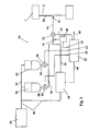
- This CTIS 20 also usually comprises means for venting the ducts 30 and 34 when the system is not in operation or when it is desired to reduce the inflation pressure.
- These means usually comprise a wheel valve disposed between the rotary joint and the internal cavity of the tire to allow not to permanently leave the rotary joint under pressure and thus increase its service life. To simplify the drawing, this valve is not shown.
- the central unit 22 is electrically connected to the control board by the conductor 45, to the pressure regulating device 28 by the conductor 44, and to the valve 32 by the driver 43.
- the central unit 22 also receives from the sensor pressure 40 an electrical signal representative of the pressure of the compressed air in the conduit 30 via the conductor 42.
- Such a device CTIS makes it possible to change the pressure in the internal cavity of the tire to a given value chosen by the operator or the control program of the central unit 22. It also makes it possible to periodically check the value of the pressure. in the internal cavity of the tire and correct it if necessary. These operations are performed by opening the valve 32 which puts in communication pneumatic the internal cavity of the tire 1, the conduit 30 and the pressure sensor 40. Depending on the measured inflation pressure value, the central unit chooses to engage or not a sequence of inflating or deflating the internal cavity of the tire.
- valves 54 and 56 are closed.
- FIG. 2 illustrates the operation of the device according to the invention.
- step 100 the device is in normal operation and regulates the inflation pressure of the internal cavity of the tire 1 to a value close to a given value Pd.
- the central unit 22 automatically triggers a control of the inflation pressure of the tire 1 - step 110.
- the comparison is made between the measured pressure signal SP and the pressure reference frame RP of the memory of the central unit 22 (step 120). If, during one of these checks, the measured pressure Pc is lower by an amount greater than a given threshold, the order of 0.3 bars, or if there is a decrease in the inflation pressure of a tire greater than a threshold ⁇ prerecorded in the repository included in the memory of the central unit, the pressure signal SP is considered abnormal.
- the central unit 22 triggers the sending in the cavity of the tire 1 of a given dose of filling product present in the tank 50 by opening the tap 54 during a short period (step 130).
- the opening of the valve 54 will project into the conduit 30 a given amount of product shutter, depending on the duration of the opening of the valve.
- the central unit 22 will bring the pressure in this conduit 30 to such a value (of the order of 4 bars for example) that the opening of the valve 32 will cause the appearance of an air flow between the compressor, the regulating device 28 and the internal cavity of the tire.
- the value of the inflation pressure Pc in the tire 1 is then periodically checked to determine whether the pressure signal remains abnormal or not (step 150) and if it remains abnormal, it is also checked relative to the conditions of flat running (RàP ) (step 160). Such conditions correspond, for example, to very low pressures close to 0.3 bars in the internal cavity of the tire. If the pressure Pc rises to be equal to or close to Pd, this repair strategy is stopped and the normal operation of the CTIS resumes in step 100. If, on the other hand, the pressure Pc continues to decrease while remaining higher than RàP threshold, greater than 0.3 bar, is sent again one or more complementary doses of product obturator. During this time, a driver alarm is maintained with appropriate restrictions on the use of the vehicle (speed ).
- step 160 When the result of step 160 indicates that the inflation pressure becomes very low and less than a second RàP threshold of the order of 0.3 bars, this indicates that the repair strategy has failed and that a rolling dish will intervene soon.
- the central unit 22 then periodically triggers the sending into the tire cavity 1 of doses of a second active product present in the reservoir 52, a lubricant (step 170).
- This product aims to reduce the friction of the walls of the sidewall of the tire on the rim hook and substantially increases the distance traveled in these conditions before the destruction of the tire.
- the driver of the vehicle is warned of the imminence of taxiing and is given the appropriate recommendations in terms of maximum speed and distance that can be envisaged (step 180).
- a flow of air is also advantageously sent to limit the heating in the tire cavity 1 due to friction (step 190).
- This air flow also has the advantage of maintaining in the cavity of the tire a minimum differential pressure, often of the order of 0.1 bar, for example. This cooling effect and this minimum pressure are in fact quite remarkable for the life of the tire and / or the safety support in the event of running flat.
- step 200, 210 When the system is also equipped with means for measuring and monitoring the temperature of the air in the internal cavity of the tire, it is advantageous to control the sending of the lubricant doses according to this measured temperature (steps 200, 210 ).
- a first threshold for example 80 degrees Celsius
- a dose is sent.
- a second threshold greater than 100 degrees Celsius
- FIG. 3 shows a mounted assembly comprising a tire 1, a wheel rim 2 and a safety support 3 disposed around the bearing surface 4 of the rim 2.
- the particular geometry of this wheel rim 2 is notably described in FIG. U.S. Patent No. 5,634,993. It has two outer and inner rim flanges, two bead seats, 6 outside and 6 inside, of different diameters and a bearing surface 4 with an engagement edge 7 and an abutment. 8.
- This rim is particularly suitable for the easy implementation of this safety support 3. This set allows the rolling despite a significant pressure drop in the tire 1.
- the support comprises two main parts, a base 9 for surround the bearing surface 4 of the rim 2 and a body 10 connected to the base 9.
- the body 10 comprises an apex 11 intended to come into contact with the tread 12 of the tire 1 in the event of zero or very low inflation pressure. This is shown in Figure 3.
- the body 10 can be of extremely varied shapes.
- Figure 4 shows a device 70 similar to that of Figure 1 but adapted to operate with mounted assemblies as shown in Figure 3; the assembled assembly is very schematically represented with the tire 1 and the wheel 2; inside the internal cavity of the tire 1 is a support 3 and a wheel module 13; this wheel module usually comprises a pressure sensor and a temperature sensor for measuring the pressure and the temperature in the internal cavity of the tire as well as means for transmitting, for example by radio, the measured data to the central unit of the tire. pilotage 22.
- the presence of the wheel module 13 in the internal cavity of the tire 1 makes it possible to follow much more regularly the evolution of the inflation pressure and the temperature in this cavity.
- the presence of the safety support 3 in the cavity of the tire 1 makes it possible to guarantee the driver of the vehicle a much greater flatbed taxiing capacity of the order of several hundred kilometers in appropriate speed and load conditions instead of a few hundred meters or a few kilometers with standard tires.
- the first test concerns the treatment of inflation pressure losses due to punctures.
- the first type of puncture is a slow puncture. In this case, the reinflation makes it possible to compensate for such a leak alone. This type of puncture was found to be involved in 40% of the punctures observed.
- the second type of puncture with a slow puncture is compensated by re-inflating until the ejection of the object causing the puncture.
- This ejection causes a marked increase in the size of the opening and thus the air leakage rate.
- the device according to the invention then makes it possible to send one or more doses of product shutter and it is found that in 30% of cases, closing the hole makes it possible to regain the tightness of the tire and thus to continue normally the planned trip.
- the device and method of the invention make it possible, by successively applying compensation and repair strategies, to maintain or regain a normal inflation pressure in the cavity. of the tire and thus be able to continue normally the planned trip.
- This test compares a flat run on support with lubricant disposed in the internal cavity of the tire or provided by a device according to the invention.
- the distance traveled with the lubricant introduced into the internal cavity of the tire by a device according to the invention is 430 km instead of 275 km in the other case.
- This result shows the advantage of being able to increase on demand the quantity of lubricating product in order to be able to substantially increase the running life of the system.
- FIG. 5 shows a device 80 according to the invention similar to that of Figure 1 but supplemented with a tank 81 containing a complementary active product for example to clean the pipes after sending doses of lubricating or sealing product.
- This tank 81 is connected as previously to the compressor 24 through the conduit 57 and the conduit 30 through the conduit 82, the valve 83 and the conduit 84.
- the valve 84 is connected and controlled by the central control unit 22 by means of the driver 85.
Landscapes
- Engineering & Computer Science (AREA)
- Mechanical Engineering (AREA)
- Treatments Of Macromolecular Shaped Articles (AREA)
- Processing And Handling Of Plastics And Other Materials For Molding In General (AREA)
- Tires In General (AREA)
- Heating, Cooling, Or Curing Plastics Or The Like In General (AREA)
Claims (30)
- Zentralisierte Vorrichtung zum Behandeln von Druckverlust- und Pannenlauf-Phänomenen an einem Fahrzeugreifen mit Mitteln außerhalb der montierten Einheit, die permanent mit dem Fahrzeug verbunden und dazu geeignet sind, mindestens einen ebenfalls außerhalb der montierten Einheit befindlichen Wirkstoff in die innere Aushöhlung des Reifens einzuspritzen oder auf andere Weise zuzuführen, dadurch gekennzeichnet, dass der Wirkstoff aus den Gruppen der Abdicht- oder Schmiermittel ausgewählt und zur Behandlung von Druckverlust- und schließlich Pannenlauf-Phänomenen geeignet ist.
- Vorrichtung nach Anspruch 1, bei der die externen Mittel außerdem Mittel zum Einspritzen oder anderweitigem Zuführen eines geeigneten Zusatzstoffes aufweisen, der sich ebenfalls außerhalb der montierten Einheit befindet.
- Vorrichtung nach Anspruch 2, bei der der Zusatzstoff unter den Mitteln ausgewählt ist, die in der Lage oder geeignet sind, die Bedingungen des Einspritzens der Wirkstoffe, die Wirkung der Wirkstoffe und die Bedingungen der Behandlung des Druckverlusts und schließlich des Pannenlaufs zu verbessern.
- Vorrichtung nach einem der Ansprüche 2 oder 3, bei der der Zusatzstoff ein Reinigungs-, Korrosionsschutz- oder Kühlmittel ist.
- Vorrichtung nach einem der Ansprüche 1 bis 4, bei der die externen Mittel außerhalb der montierten Einheit mindestens einen Behälter oder eine Quelle eines Wirkstoffs aufweisen, der bei Druckverlust oder Pannenlauf in die innere Aushöhlung des Reifens gespritzt oder auf andere Weise zugeführt wird.
- Vorrichtung nach einem der Ansprüche 1 bis 5, bei der die externen Mittel außerdem Mittel zum Zuführen oder Einspritzen mindestens des Wirkstoffs in die innere Aushöhlung des Reifens bei Druckverlust oder Pannenlauf aufweisen.
- Vorrichtung nach einem der Ansprüche 1 bis 6, bei der die Mittel zum Zuführen oder Einspritzen mindestens eines Wirkstoffs Luft oder ein inertes Gas wie Stickstoff oder einen nicht toxischen, nicht umweltschädlichen und nicht entflammbaren Kohlenwasserstoff im komprimierten Zustand einsetzen.
- Vorrichtung nach einem der Ansprüche 1 bis 7, bei der die externen Mittel eine Reserve oder Quelle eines kühlenden Produkts aufweisen, das beim Pannenlauf in die innere Aushöhlung des Reifens eingespritzt oder auf andere Weise zugeführt wird.
- Vorrichtung nach Anspruch 8, bei der das kühlende Produkt Luft, Stickstoff oder ein gleichwertiges Gas ist.
- Vorrichtung nach einem der Ansprüche 1 bis 9, bei dem die externen Mittel Folgendes aufweisen oder zusammenwirken mit:- Mitteln zum Messen des Drucks oder anderer für die Luft im Reifen charakteristischer Merkmale, die mindestens ein "charakteristisches Signal" für den Zustand der Luft in der inneren Aushöhlung des Reifens erzeugen, das heißt für den Druck und/oder die Änderungen des Drucks über die Zeit (nachfolgend "Drucksignal" genannt);- Mitteln zum Steuern der Zufuhr- oder Einspritzmittel mit mindestens einem Speicher, einem Vergleicher und einem Steuerprogramm, die geeignet sind,· das Drucksignal zu empfangen und zu verarbeiten;· es mit einem im Speicher geladenen Druck-Bezugssystem zu vergleichen; und· abhängig vom Ergebnis dieses Vergleichs über die Zufuhr oder das Einspritzen von Luft oder einem anderen komprimierten Gas und/oder Wirkstoff zu entscheiden und diese zu programmieren, und zwar in variablen Kombinationen von Mengen, Anteilen und Durchsätzen oder Dosen, die geeignet sind, abhängig vom Programm und vom Speicher bestmöglich auf das empfangene Drucksignal zu reagieren.
- Vorrichtung nach Anspruch 10, bei der das Druck-Bezugssystem Wertangaben für den Druck, den Druckunterschied gegenüber einem Referenzdruck, insbesondere dem Betriebsdruck, und für die Änderungsgeschwindigkeit des Drucks, das heißt

- Vorrichtung nach Anspruch 10 oder 11, bei der sich die Mittel zum Messen der Merkmale der Luft im Reifen, die das Drucksignal erzeugen, an oder in der montierten Einheit befinden.
- Vorrichtung nach Anspruch 10 oder 11, bei der sich die Mittel zum Messen der Merkmale der Luft im Reifen, die das Drucksignal erzeugen, außerhalb der montierten Einheit befinden.
- Vorrichtung nach einem der Ansprüche 10 bis 13, bei der die Mittel zum Erzeugen des Drucksignals Mittel zum Messen der Temperatur der Luft der inneren Aushöhlung des Reifens und ihrer Entwicklung über die Zeit umfassen.
- Vorrichtung nach einem der Ansprüche 1 bis 14, bei der die Mittel zum Zuführen oder Einspritzen mindestens eines Wirkstoffs einen Generator oder eine Quelle von Luft oder eines anderen komprimierten Gases sowie Leitungen und Ventile oder Hähne aufweisen, die eine Verbindungsleitung zwischen dem Generator oder der Quelle, den Behältern und der inneren Aushöhlung des Reifens bilden.
- Vorrichtung nach Anspruch 15, bei der der Generator oder die Quelle von Druckluft aus einem Behälter für komprimierte Luft wie Umgebungsluft oder ein inertes Gas wie Stickstoff oder einen nicht toxischen, nicht entflammbaren und nicht umweltschädlichen Kohlenwasserstoff besteht.
- Vorrichtung nach Anspruch 15, bei der der Generator von komprimierter Luft aus einem Kompressor besteht.
- Vorrichtung nach Anspruch 17, bei der der Kompressor, der die Aufpumpluft liefert, auch die Kühlluft liefern kann.
- Vorrichtung nach einem der Ansprüche 1 bis 18 mit einem zentralisierten System zum Aufpumpen von mindestens einem Fahrzeugreifen oder CTIS, das im Wesentlichen aus Folgendem besteht:- einer zentralen Steuereinheit;- einem Kompressor, der komprimierte Luft oder komprimiertes Gas erzeugt;- einer Vorrichtung zum Regeln des Drucks auf einen festen oder von der zentralen Einheit gesteuerten Wert; und- Mitteln zur pneumatischen Verbindung des Kompressors, der Druckregelvorrichtung und der inneren Aushöhlung des Reifens;wobei die Vorrichtung außerdem mindestens einen Behälter für einen Wirkstoff aufweist, der über Leitungen und Hähne oder Ventile mit den Elementen des CTIS verbunden ist, und wobei die zentrale Einheit einen Speicher und ein Programm aufweist, die variable Kombinationen von Mengen, Anteilen und Durchsätzen oder Dosen von Aufpumpluft, Wirkstoff und/oder geeignetem Zusatzstoff, insbesondere von Abdicht- und/oder Schmiermittel und/oder geeigneten Zusatzstoffen wie Reinigungs-, Korrosionsschutzmitteln, Luft (oder ein Gas) zum Kühlen oder ein flüssiges Kühlmittel wie Wasser oder einen Alkohol oder ähnliche Produkte verwalten und einsetzen können.
- Verfahren zum zentralisierten Behandeln von Druckverlust- und Pannenlauf-Phänomenen an einem Fahrzeugreifen, dadurch gekennzeichnet, dass es Folgendes einsetzt:- Mittel zum Messen des Drucks oder anderer für die Luft im Reifen charakteristischer Merkmale, die mindestens ein "charakteristisches Signal" für den Zustand der Luft in der inneren Aushöhlung des Reifens erzeugen, das heißt für den Druck und/oder die Änderungen des Drucks über die Zeit (nachfolgend als "Drucksignal" bezeichnet);- gegebenenfalls Mittel zum Messen der Temperatur der Luft im Reifen;- Mittel zum Zuführen oder Einspritzen von Luft oder einem anderen komprimierten Gas und von mindestens einem Wirkstoff in die innere Aushöhlung eines Reifens;- Mittel zum Steuern der Zufuhr- oder Einspritzmittel mit mindestens einem Speicher, einem Vergleicher und einem Steuerprogramm, die dazu geeignet sind:- das Drucksignal zu empfangen und zu verarbeiten;- es mit einem im Speicher geladenen Druck-Bezugssystem zu vergleichen;- wobei es das Programm erlaubt, abhängig vom Ergebnis des Vergleichs über die Zufuhr oder das Einspritzen von Luft oder einem anderen komprimierten Gas, von Wirkstoff und/oder einem geeignetem Zusatzstoff in den Reifen zu entscheiden und diese zu programmieren, und zwar in variablen Kombinationen von Mengen, Anteilen und Durchsätzen oder Dosen, die geeignet sind, um abhängig vom Programm und vom Speicher bestmöglich auf das empfangene Drucksignal zu reagieren.
- Verfahren nach Anspruch 20, bei dem das Druck-Bezugssystem Wertangaben für den Druck, den Druckunterschied gegenüber einem Referenzdruck, insbesondere dem Betriebsdruck, und für die Änderungsgeschwindigkeit des Drucks, das heißt

- Verfahren nach Anspruch 20 oder 21, bei dem die Steuermittel, wenn das Ergebnis des Vergleichs zwischen dem Drucksignal (SP) und dem Druck-Bezugssystem (RP) anormal ist, die Zufuhr- oder Einspritzmittel veranlassen, eine vorher festgelegte Dosis an abdichtendem Wirkstoff in die innere Aushöhlung des Reifens zu schicken.
- Verfahren nach Anspruch 22, bei dem die Steuermittel außerdem einen "Pannenalarm" an den Fahrer übertragen.
- Verfahren nach einem der Ansprüche 22 oder 23, bei dem das Ergebnis des Vergleichs zwischen dem Drucksignal (SP) und dem Druck-Bezugssystem (RP) anormal ist, wenn die Differenz zwischen dem gemessenen Druck und dem Einstelldruck einen gegebenen Grenzwert übersteigt.
- Verfahren nach einem der Ansprüche 22 oder 23, bei dem das Ergebnis des Vergleichs zwischen dem Drucksignal (SP) und dem Druck-Bezugssystem (RP) anormal ist, wenn die über eine gegebene Zeit gemessene Druckänderung einen gegebenen Grenzwert übersteigt.
- Verfahren nach einem der Ansprüche 20 bis 25, bei dem die Steuermittel, wenn das Ergebnis des Vergleichs zwischen dem Drucksignal (SP) und dem Druck-Bezugssystem (RP) auf Pannenlauf-Bedingungen (RäP) hinweist, die Zufuhr- oder Einspritzmittel veranlassen, eine vorher festgelegte Dosis an schmierendem Wirkstoff in die innere Aushöhlung des Reifens zu schicken.
- Verfahren nach Anspruch 26, bei dem die Steuermittel außerdem einen "Pannenlauf-Alarm" an den Fahrer übertragen.
- Verfahren nach einem der Ansprüche 26 oder 27, bei dem die Steuermittel die Zufuhr- oder Einspritzmittel veranlassen, außerdem eine kleine Menge Luft oder eines anderen Gases zum Kühlen in die innere Aushöhlung des Reifens zu schicken.
- Verfahren nach einem der Ansprüche 26 bis 28, bei dem die Mittel zum Messen der Temperatur der Luft in der inneren Aushöhlung des Reifens diese Temperatur an die Steuermittel übermitteln, die, falls sie feststellen, dass unter Berücksichtigung der Nutzungsbedingungen (Last, Geschwindigkeit, Außentemperatur usw.) der Temperaturwert einen vorher festgelegten Grenzwert übersteigt, eine oder mehrere zusätzliche Dosen an Schmiermittel versenden lassen.
- Verfahren nach Anspruch 29, bei dem die Steuermittel, wenn sie feststellen, dass der Wert der Temperatur in der inneren Aushöhlung des Reifens einen vorher festgelegten zweiten Grenzwert übersteigt, an den Fahrer des Fahrzeugs einen Alarm übertragen lassen, der zum sofortigen Anhalten auffordert.
Applications Claiming Priority (3)
| Application Number | Priority Date | Filing Date | Title |
|---|---|---|---|
| FR0202669 | 2002-03-01 | ||
| FR0202669A FR2836656B1 (fr) | 2002-03-01 | 2002-03-01 | Dispositif et procede de traitement des phenomenes de perte de pression et de roulage a plat des pneumatiques d'un vehicule |
| PCT/EP2003/001942 WO2003074298A1 (fr) | 2002-03-01 | 2003-02-26 | Dispositif et procede de traitement des phenomenes de perte de pression et de roulage a plat des pneumatiques d'un vehicule |
Publications (2)
| Publication Number | Publication Date |
|---|---|
| EP1490239A1 EP1490239A1 (de) | 2004-12-29 |
| EP1490239B1 true EP1490239B1 (de) | 2007-01-24 |
Family
ID=27741389
Family Applications (1)
| Application Number | Title | Priority Date | Filing Date |
|---|---|---|---|
| EP03743332A Expired - Lifetime EP1490239B1 (de) | 2002-03-01 | 2003-02-26 | Vorrichtung und verfahren zum behandeln der phänomene des druckverlusts und des pannenlaufs bei einem fahrzeugreifen |
Country Status (8)
| Country | Link |
|---|---|
| US (1) | US7287565B2 (de) |
| EP (1) | EP1490239B1 (de) |
| JP (1) | JP4283117B2 (de) |
| AT (1) | ATE352432T1 (de) |
| AU (1) | AU2003220781A1 (de) |
| DE (1) | DE60311438T2 (de) |
| FR (1) | FR2836656B1 (de) |
| WO (1) | WO2003074298A1 (de) |
Families Citing this family (26)
| Publication number | Priority date | Publication date | Assignee | Title |
|---|---|---|---|---|
| JP2005297851A (ja) * | 2004-04-14 | 2005-10-27 | Toyota Motor Corp | 車輪状態調整システム |
| JP4289561B2 (ja) * | 2004-12-24 | 2009-07-01 | 横浜ゴム株式会社 | 車両の異常検出方法及びその装置並びにそのセンサユニット |
| JP4189680B2 (ja) * | 2005-03-31 | 2008-12-03 | オムロン株式会社 | タイヤ圧力モニタリングシステム及びパンク自動修理装置 |
| JP4816102B2 (ja) * | 2006-01-26 | 2011-11-16 | 日産自動車株式会社 | タイヤ空気圧監視システム |
| IL183313A0 (en) * | 2007-05-20 | 2007-09-20 | Yuri Ginzburg | Tire inflation system |
| US8201575B2 (en) * | 2007-07-17 | 2012-06-19 | Master Pneumatic-Detroit, Inc. | Air pressure regulator with flow sensor |
| DE202010008453U1 (de) * | 2010-09-06 | 2010-11-04 | Ptg Reifendruckregelsysteme Gmbh | Reifendruckregelanlage für ein Kraftfahrzeug sowie Drehdurchführung |
| DE202011051737U1 (de) | 2011-10-24 | 2011-11-04 | Ptg Reifendruckregelsysteme Gmbh | Drehdurchführung als Teil einer Reifendruckregelanlage eines Fahrzeuges |
| US8739631B2 (en) * | 2012-02-28 | 2014-06-03 | Sperry Rail, Inc. | System and method for non-destructive testing of railroad rails using ultrasonic apparatuses mounted within fluid-filled tires maintained at constant temperatures |
| EP2653323B1 (de) * | 2012-04-19 | 2016-03-23 | DANA ITALIA S.p.A | Achsanordnung für Reifenfüllsystem |
| US9259982B2 (en) * | 2012-10-05 | 2016-02-16 | Consumer Products International Llc. | Currency operated tire inflation and repair apparatus and methods |
| DE102012023509A1 (de) * | 2012-11-30 | 2014-06-05 | Wabco Gmbh | Verfahren zur Regelung oder Einstellung eines Reifenfülldrucks an Fahrzeugreifen und Reifenfülldruck-Einstellvorrichtung |
| DE102014203260B4 (de) * | 2014-02-24 | 2022-06-15 | Bayerische Motoren Werke Aktiengesellschaft | Steuereinheit für die Einstellung des Innendrucks in Fahrzeugreifen |
| US10315472B2 (en) | 2014-04-08 | 2019-06-11 | Consumer Products International Llc. | Currency operated automobile fluid dispensing and/or recovery assemblies and methods |
| CA2954021A1 (en) | 2014-07-02 | 2016-01-07 | Dana Italia S.P.A. | Rotary seal for a central tire inflation system |
| PT3194184T (pt) * | 2014-09-17 | 2022-12-09 | Ste Ind S R L | Dispositivo de transmissão e método para transmissão em modo sem fios de parâmetros sujeitos a medição |
| GB2540417B (en) * | 2015-07-17 | 2019-04-10 | Jaguar Land Rover Ltd | Central tyre inflation system |
| DE202015105859U1 (de) | 2015-11-04 | 2017-02-07 | Ptg Reifendruckregelsysteme Gmbh | Radventilanordnung sowie Reifendruckregelanlage mit wenigstens einer solchen Radventilanordnung |
| WO2017116626A1 (en) * | 2015-12-29 | 2017-07-06 | Bridgestone Americas Tire Operations, Llc | Air storage system for rapid tire inflation |
| US11021023B2 (en) | 2015-12-29 | 2021-06-01 | Bridgestone Americas Tire Operations, Llc | Rapid tire inflation system with air compressor |
| US10953707B2 (en) | 2015-12-29 | 2021-03-23 | Bridgestone Americas Tire Operations, Llc | Air distribution system for rapid tire inflation |
| DE102016119272A1 (de) * | 2016-10-11 | 2018-04-12 | Dr. Ing. H.C. F. Porsche Aktiengesellschaft | Mechanisch angetriebene Reifendruckerzeugung |
| ES3055309T3 (en) * | 2016-12-15 | 2026-02-11 | Active Tools Int Hk Ltd | Tire maintenance means |
| US11117426B1 (en) | 2021-03-24 | 2021-09-14 | Ptg Reifendruckregelsysteme Gmbh | Rotary transmission leadthrough as part of a tire pressure control system |
| CN114643816B (zh) * | 2021-08-30 | 2023-05-16 | 长城汽车股份有限公司 | 自修复轮胎的异物刺穿提醒方法及相关装置 |
| CN114379291B (zh) * | 2022-03-24 | 2022-06-07 | 山东玲珑轮胎股份有限公司 | 一种轮胎内支撑安全锁紧装置 |
Family Cites Families (18)
| Publication number | Priority date | Publication date | Assignee | Title |
|---|---|---|---|---|
| US4054168A (en) | 1976-04-15 | 1977-10-18 | The Goodyear Tire & Rubber Company | Fluid dispensing apparatus for tire wheel assembly |
| US4212339A (en) * | 1979-01-02 | 1980-07-15 | The Goodyear Tire & Rubber Company | Tire/wheel assembly with low molecular weight coolant-lubricant |
| US4343338A (en) * | 1981-02-25 | 1982-08-10 | Caterpillar Tractor Co. | Tire cooling system and method |
| GB2155329A (en) * | 1984-03-08 | 1985-09-25 | Kim Drummond Rainsford | A pharmaceutical formulation containing azapropazone |
| US4619303A (en) * | 1984-06-04 | 1986-10-28 | Eaton Corporation | Vehicle air system including central tire inflation system |
| US5034993A (en) * | 1989-03-15 | 1991-07-23 | Motorola, Inc. | Method for allocating communication resources among RF communications systems |
| US5070917A (en) * | 1989-06-14 | 1991-12-10 | Ferris James E | Pressurized fluid-drivable device for injecting a treatment liquid stored therein into a tire or other enclosed space |
| US5178701A (en) * | 1991-05-31 | 1993-01-12 | Jorge Taylor | Chemical sealant device for repairing flat tires |
| US5244027A (en) * | 1991-09-03 | 1993-09-14 | Eaton Corporation | Vent for vehicle tire inflation system |
| JPH0753934Y2 (ja) * | 1991-10-25 | 1995-12-13 | リョービ株式会社 | カンナ胴のロック機構 |
| US5648406A (en) | 1992-02-14 | 1997-07-15 | Specialty Chemical Resources, Inc. | Tire sealant and inflator |
| US5295525A (en) | 1992-06-22 | 1994-03-22 | Michelin Recherche Et Technique S.A. | Puncture sealant formulation |
| FR2699121B1 (fr) | 1992-12-11 | 1995-03-17 | Michelin & Cie | Ensemble formé d'un pneumatique, d'une jante et d'un anneau de soutien. |
| US5516379A (en) * | 1994-10-20 | 1996-05-14 | Eaton Corporation | CTI program pressure setting override |
| EP0786361B1 (de) | 1996-01-26 | 2002-01-02 | COMPAGNIE GENERALE DES ETABLISSEMENTS MICHELIN-MICHELIN & CIE | Verfahren zur Auswertung von Signalen einer Reifendruck-Überwachungsvorrichtung eines fahrenden Fahrzeugs |
| DE19800133A1 (de) * | 1998-01-03 | 1998-09-17 | Bernhard Dipl Ing Geilich | Einrichtung zur selbsttätigen Aufrechterhaltung des Reifenbetriebsdrucks sowie zur selbsttätigen Abdichtung von Undichtigkeiten des Reifenschlauchs bei Zweirädern |
| FR2811329A1 (fr) | 2000-07-07 | 2002-01-11 | Michelin Soc Tech | Composition lubrifiante pour interface enveloppe de pneumatique/appui de securite en roulage a plat |
| US6758250B2 (en) * | 2002-05-31 | 2004-07-06 | Michelin Recherche Et Technique S.A. | Lubricant release system |
-
2002
- 2002-03-01 FR FR0202669A patent/FR2836656B1/fr not_active Expired - Fee Related
-
2003
- 2003-02-26 AT AT03743332T patent/ATE352432T1/de not_active IP Right Cessation
- 2003-02-26 WO PCT/EP2003/001942 patent/WO2003074298A1/fr not_active Ceased
- 2003-02-26 AU AU2003220781A patent/AU2003220781A1/en not_active Abandoned
- 2003-02-26 EP EP03743332A patent/EP1490239B1/de not_active Expired - Lifetime
- 2003-02-26 JP JP2003572785A patent/JP4283117B2/ja not_active Expired - Fee Related
- 2003-02-26 DE DE60311438T patent/DE60311438T2/de not_active Expired - Lifetime
-
2004
- 2004-08-26 US US10/927,219 patent/US7287565B2/en not_active Expired - Fee Related
Also Published As
| Publication number | Publication date |
|---|---|
| EP1490239A1 (de) | 2004-12-29 |
| DE60311438D1 (de) | 2007-03-15 |
| US20050045259A1 (en) | 2005-03-03 |
| WO2003074298A1 (fr) | 2003-09-12 |
| AU2003220781A1 (en) | 2003-09-16 |
| FR2836656B1 (fr) | 2004-05-28 |
| ATE352432T1 (de) | 2007-02-15 |
| JP4283117B2 (ja) | 2009-06-24 |
| US7287565B2 (en) | 2007-10-30 |
| JP2005526649A (ja) | 2005-09-08 |
| FR2836656A1 (fr) | 2003-09-05 |
| DE60311438T2 (de) | 2007-11-15 |
Similar Documents
| Publication | Publication Date | Title |
|---|---|---|
| EP1490239B1 (de) | Vorrichtung und verfahren zum behandeln der phänomene des druckverlusts und des pannenlaufs bei einem fahrzeugreifen | |
| EP1375197B1 (de) | Reifen und felge | |
| CA2716478A1 (fr) | Dispositif anti-crevaison pour ensemble monte non pneumatique de vehicule a deux roues, et cet ensemble monte l'incorporant | |
| JP6896648B2 (ja) | 車両の負荷を見積もる方法 | |
| WO2008142679A2 (en) | Tire inflation system | |
| US20100300591A1 (en) | Self-inflating wheel | |
| EP2303609B1 (de) | Entlüftungsvorrichtung für eine montierte einheit und verfahren zum entleeren einer montierten einheit | |
| WO2023110655A1 (fr) | Pneumatique conçu pour une mise à plat maîtrisée | |
| JP4927740B2 (ja) | 内圧リザーバ及び圧力変化警報装置付きホイールアセンブリ | |
| FR2900596A1 (fr) | Procede de surveillance de l'etat operationnel d'un pneumatique | |
| EP3554860B1 (de) | Anordnung aus reifenkarkasse und rad mit verbessertem selbstversiegelndem produkt | |
| EP2595845A1 (de) | Druckprüfungs- und/oder einstellungsverfahren und vorrichtung für eine reifen-rad-anordnung | |
| EP1670651A1 (de) | Reifen für schwerfahrzeugen, lauffläche und verwendung davon | |
| JP2008023764A (ja) | シーリング・ポンプアップ装置 | |
| EP0912354A1 (de) | Aufblasbare struktur für luftreifen | |
| CN109397989A (zh) | 发泡填充式车轮及其制造方法 | |
| EP4107009B1 (de) | Reifen mit niedriger seitenwandhöhe | |
| JP4990485B2 (ja) | タイヤとリムとの組立体およびこの組立体の内側に配置する中空粒子群 | |
| CN118810304B (zh) | 一种自动充放气型车轮及车轮自动充放气方法 | |
| EP4107011B1 (de) | Reifen mit niedriger seitenwandhöhe | |
| WO2014014444A1 (en) | Kit for restoring tire bead integrity | |
| LU100179B1 (fr) | Pneu avec chambre à air de secours | |
| EP1232881B1 (de) | Regelsystem für den Druck in einer Kapazität, wie ein Fahrzeugrad | |
| CN101198481B (zh) | 轮胎和轮圈的装配体及空心粒子 | |
| US20130292908A1 (en) | Roadside repair kit for restoring tire bead integrity |
Legal Events
| Date | Code | Title | Description |
|---|---|---|---|
| PUAI | Public reference made under article 153(3) epc to a published international application that has entered the european phase |
Free format text: ORIGINAL CODE: 0009012 |
|
| 17P | Request for examination filed |
Effective date: 20041001 |
|
| AK | Designated contracting states |
Kind code of ref document: A1 Designated state(s): AT BE BG CH CY CZ DE DK EE ES FI FR GB GR HU IE IT LI LU MC NL PT SE SI SK TR |
|
| AX | Request for extension of the european patent |
Extension state: AL LT LV MK RO |
|
| GRAP | Despatch of communication of intention to grant a patent |
Free format text: ORIGINAL CODE: EPIDOSNIGR1 |
|
| GRAS | Grant fee paid |
Free format text: ORIGINAL CODE: EPIDOSNIGR3 |
|
| GRAA | (expected) grant |
Free format text: ORIGINAL CODE: 0009210 |
|
| RAP1 | Party data changed (applicant data changed or rights of an application transferred) |
Owner name: SOCIETE DE TECHNOLOGIE MICHELIN Owner name: MICHELIN RECHERCHE ET TECHNIQUE S.A. |
|
| AK | Designated contracting states |
Kind code of ref document: B1 Designated state(s): AT BE BG CH CY CZ DE DK EE ES FI FR GB GR HU IE IT LI LU MC NL PT SE SI SK TR |
|
| PG25 | Lapsed in a contracting state [announced via postgrant information from national office to epo] |
Ref country code: SI Free format text: LAPSE BECAUSE OF FAILURE TO SUBMIT A TRANSLATION OF THE DESCRIPTION OR TO PAY THE FEE WITHIN THE PRESCRIBED TIME-LIMIT Effective date: 20070124 Ref country code: DK Free format text: LAPSE BECAUSE OF FAILURE TO SUBMIT A TRANSLATION OF THE DESCRIPTION OR TO PAY THE FEE WITHIN THE PRESCRIBED TIME-LIMIT Effective date: 20070124 Ref country code: IE Free format text: LAPSE BECAUSE OF FAILURE TO SUBMIT A TRANSLATION OF THE DESCRIPTION OR TO PAY THE FEE WITHIN THE PRESCRIBED TIME-LIMIT Effective date: 20070124 Ref country code: NL Free format text: LAPSE BECAUSE OF FAILURE TO SUBMIT A TRANSLATION OF THE DESCRIPTION OR TO PAY THE FEE WITHIN THE PRESCRIBED TIME-LIMIT Effective date: 20070124 Ref country code: AT Free format text: LAPSE BECAUSE OF FAILURE TO SUBMIT A TRANSLATION OF THE DESCRIPTION OR TO PAY THE FEE WITHIN THE PRESCRIBED TIME-LIMIT Effective date: 20070124 Ref country code: FI Free format text: LAPSE BECAUSE OF FAILURE TO SUBMIT A TRANSLATION OF THE DESCRIPTION OR TO PAY THE FEE WITHIN THE PRESCRIBED TIME-LIMIT Effective date: 20070124 |
|
| REG | Reference to a national code |
Ref country code: GB Ref legal event code: FG4D Free format text: NOT ENGLISH |
|
| REG | Reference to a national code |
Ref country code: CH Ref legal event code: EP |
|
| PG25 | Lapsed in a contracting state [announced via postgrant information from national office to epo] |
Ref country code: LI Free format text: LAPSE BECAUSE OF NON-PAYMENT OF DUE FEES Effective date: 20070228 Ref country code: MC Free format text: LAPSE BECAUSE OF NON-PAYMENT OF DUE FEES Effective date: 20070228 Ref country code: CH Free format text: LAPSE BECAUSE OF NON-PAYMENT OF DUE FEES Effective date: 20070228 |
|
| REG | Reference to a national code |
Ref country code: IE Ref legal event code: FG4D Free format text: LANGUAGE OF EP DOCUMENT: FRENCH |
|
| REF | Corresponds to: |
Ref document number: 60311438 Country of ref document: DE Date of ref document: 20070315 Kind code of ref document: P |
|
| PG25 | Lapsed in a contracting state [announced via postgrant information from national office to epo] |
Ref country code: SE Free format text: LAPSE BECAUSE OF FAILURE TO SUBMIT A TRANSLATION OF THE DESCRIPTION OR TO PAY THE FEE WITHIN THE PRESCRIBED TIME-LIMIT Effective date: 20070424 |
|
| PG25 | Lapsed in a contracting state [announced via postgrant information from national office to epo] |
Ref country code: BG Free format text: LAPSE BECAUSE OF EXPIRATION OF PROTECTION Effective date: 20070425 |
|
| PG25 | Lapsed in a contracting state [announced via postgrant information from national office to epo] |
Ref country code: ES Free format text: LAPSE BECAUSE OF FAILURE TO SUBMIT A TRANSLATION OF THE DESCRIPTION OR TO PAY THE FEE WITHIN THE PRESCRIBED TIME-LIMIT Effective date: 20070505 |
|
| PG25 | Lapsed in a contracting state [announced via postgrant information from national office to epo] |
Ref country code: PT Free format text: LAPSE BECAUSE OF FAILURE TO SUBMIT A TRANSLATION OF THE DESCRIPTION OR TO PAY THE FEE WITHIN THE PRESCRIBED TIME-LIMIT Effective date: 20070625 |
|
| NLV1 | Nl: lapsed or annulled due to failure to fulfill the requirements of art. 29p and 29m of the patents act | ||
| GBV | Gb: ep patent (uk) treated as always having been void in accordance with gb section 77(7)/1977 [no translation filed] |
Effective date: 20070124 |
|
| REG | Reference to a national code |
Ref country code: IE Ref legal event code: FD4D |
|
| REG | Reference to a national code |
Ref country code: CH Ref legal event code: PL |
|
| PG25 | Lapsed in a contracting state [announced via postgrant information from national office to epo] |
Ref country code: GB Free format text: LAPSE BECAUSE OF FAILURE TO SUBMIT A TRANSLATION OF THE DESCRIPTION OR TO PAY THE FEE WITHIN THE PRESCRIBED TIME-LIMIT Effective date: 20070124 Ref country code: SK Free format text: LAPSE BECAUSE OF FAILURE TO SUBMIT A TRANSLATION OF THE DESCRIPTION OR TO PAY THE FEE WITHIN THE PRESCRIBED TIME-LIMIT Effective date: 20070124 |
|
| PLBE | No opposition filed within time limit |
Free format text: ORIGINAL CODE: 0009261 |
|
| STAA | Information on the status of an ep patent application or granted ep patent |
Free format text: STATUS: NO OPPOSITION FILED WITHIN TIME LIMIT |
|
| BERE | Be: lapsed |
Owner name: SOC. DE TECHNOLOGIE MICHELIN Effective date: 20070228 Owner name: MICHELIN RECHERCHE ET TECHNIQUE S.A. Effective date: 20070228 |
|
| 26N | No opposition filed |
Effective date: 20071025 |
|
| PG25 | Lapsed in a contracting state [announced via postgrant information from national office to epo] |
Ref country code: CZ Free format text: LAPSE BECAUSE OF FAILURE TO SUBMIT A TRANSLATION OF THE DESCRIPTION OR TO PAY THE FEE WITHIN THE PRESCRIBED TIME-LIMIT Effective date: 20070124 Ref country code: BE Free format text: LAPSE BECAUSE OF NON-PAYMENT OF DUE FEES Effective date: 20070228 |
|
| PG25 | Lapsed in a contracting state [announced via postgrant information from national office to epo] |
Ref country code: GR Free format text: LAPSE BECAUSE OF FAILURE TO SUBMIT A TRANSLATION OF THE DESCRIPTION OR TO PAY THE FEE WITHIN THE PRESCRIBED TIME-LIMIT Effective date: 20070425 |
|
| PG25 | Lapsed in a contracting state [announced via postgrant information from national office to epo] |
Ref country code: EE Free format text: LAPSE BECAUSE OF FAILURE TO SUBMIT A TRANSLATION OF THE DESCRIPTION OR TO PAY THE FEE WITHIN THE PRESCRIBED TIME-LIMIT Effective date: 20070124 |
|
| PG25 | Lapsed in a contracting state [announced via postgrant information from national office to epo] |
Ref country code: CY Free format text: LAPSE BECAUSE OF FAILURE TO SUBMIT A TRANSLATION OF THE DESCRIPTION OR TO PAY THE FEE WITHIN THE PRESCRIBED TIME-LIMIT Effective date: 20070124 |
|
| PG25 | Lapsed in a contracting state [announced via postgrant information from national office to epo] |
Ref country code: LU Free format text: LAPSE BECAUSE OF NON-PAYMENT OF DUE FEES Effective date: 20070226 |
|
| PG25 | Lapsed in a contracting state [announced via postgrant information from national office to epo] |
Ref country code: HU Free format text: LAPSE BECAUSE OF FAILURE TO SUBMIT A TRANSLATION OF THE DESCRIPTION OR TO PAY THE FEE WITHIN THE PRESCRIBED TIME-LIMIT Effective date: 20070725 Ref country code: TR Free format text: LAPSE BECAUSE OF FAILURE TO SUBMIT A TRANSLATION OF THE DESCRIPTION OR TO PAY THE FEE WITHIN THE PRESCRIBED TIME-LIMIT Effective date: 20070124 |
|
| REG | Reference to a national code |
Ref country code: FR Ref legal event code: PLFP Year of fee payment: 14 |
|
| REG | Reference to a national code |
Ref country code: FR Ref legal event code: PLFP Year of fee payment: 15 |
|
| REG | Reference to a national code |
Ref country code: FR Ref legal event code: PLFP Year of fee payment: 16 |
|
| PGFP | Annual fee paid to national office [announced via postgrant information from national office to epo] |
Ref country code: DE Payment date: 20180219 Year of fee payment: 16 |
|
| PGFP | Annual fee paid to national office [announced via postgrant information from national office to epo] |
Ref country code: IT Payment date: 20180227 Year of fee payment: 16 Ref country code: FR Payment date: 20180223 Year of fee payment: 16 |
|
| REG | Reference to a national code |
Ref country code: DE Ref legal event code: R119 Ref document number: 60311438 Country of ref document: DE |
|
| PG25 | Lapsed in a contracting state [announced via postgrant information from national office to epo] |
Ref country code: DE Free format text: LAPSE BECAUSE OF NON-PAYMENT OF DUE FEES Effective date: 20190903 |
|
| PG25 | Lapsed in a contracting state [announced via postgrant information from national office to epo] |
Ref country code: FR Free format text: LAPSE BECAUSE OF NON-PAYMENT OF DUE FEES Effective date: 20190228 Ref country code: IT Free format text: LAPSE BECAUSE OF NON-PAYMENT OF DUE FEES Effective date: 20190226 |